Week 6::Electronics Design
Assignments:
redraw the echo hello-world board
add (at least) a button and LED (with current-limiting resistor)
check the design rules, and make it
extra credit: simulate its operation
To perform the tasks in this this week I decided to use the following software:
- Photoshop CS5: For the layout and retouching of images for the web.
- Eagle v7.20: To redraw the echo hello-world board
- Fab Modules: To send orders to Modela Machine
- 123d Circuits: Try to simulate hello-world board (not jet)
Redraw the echo hello-world board
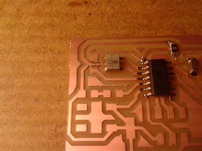
I installed the freeware version of eagle and I've added the component libraries provided by the academy fab. Starting with the schematic design, select all parts required for after making connections. new components added to the design provided are: a button, a green LED and a resistor. According to calculations, this led I need a resistance of 290 Ohm ([5v-2.1] / 10mA), otherwise we consider the voltage drop of the LED have a value of 500 Ohm (5V / 10mA). The resistance will use is one of 499 Ohm. I have placed these new elements in the lower left side near the connections will use the aTtiny44 (PB2 and PA7).
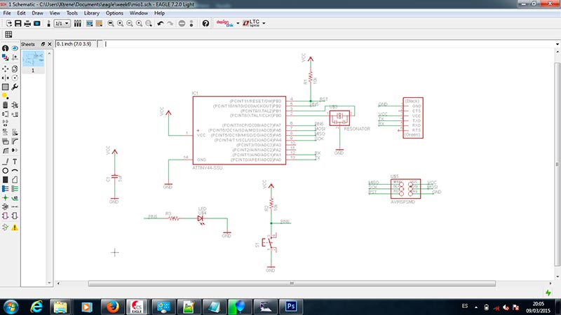
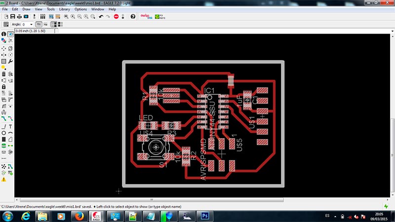
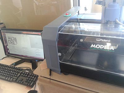
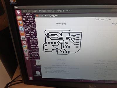
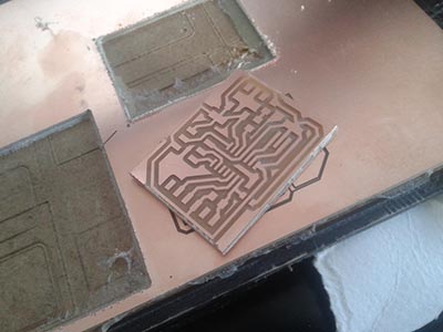
I had to make a bridge on the circuit to connect all the GND. Once all the elements are placed, I generate a png file to use on the machine model. By using Fab modules set up the first milling path to generate the tracks, and send the control order to the machine, moments later I realize the first fault committed, I invested the colors of PNG file and have milling around in reverse, again with the correct colors go back to send the order through Fab modules , now the board is properly milled, lacking only give the order to cut the outer edge.
Modela Machine:
Fail:
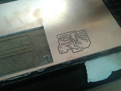
Bad Png file:
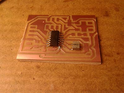
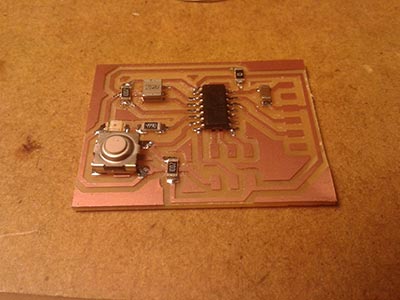
Final Board
The result is correct. Prepare material for welding of components required. The component list is as follows:
- 1x Microcontrolator Attiny44A
- 1x 20MHz Resonator
- 1x Jumper Header(2x3)(J1)
- 1x Jumper Header(1x6)(J2)
- 1x Resistor 0
- 1x Resistor 499
- 2x Resistor 10K
- 1x Capacitor 1uF
- 1x Green LED
- 2x Switch button
with a little soldering flux:
Resistor 0 for Bridge:
All electronics components:
Final Board
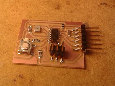
This time, I used a soldering iron with thinner tip and for weld the IC I used a bit of FLUX, has been quite easier.
Files:
- Eagle: Schematic File: Download
- Eagle: Board file: Download
- PNG: tracks: Download
- PNG: Border cut: Download