Week 11:: Output Devices
Assignments:
add an output device to a microcontroller board you've designed and program it to do something
To perform the tasks in this this week I decided to use the following software:
- Photoshop CS5: For the layout and retouching of images for the web.
- Eagle To design the the board
- Fab Modules: For the modela Machine
DC Motor (H-bridge)
This circuit controls a DC motor and rotated in different directions and at different speeds, the circuit has a driver ATtiny continuously and motor (an H-bridge). I have completely redesigned the board provided by the Fab Academy and used the code that comes with the job (with some minor modifications to control pan or speed).
Being a DC motor, the communication protocol is based on electric current intensities and polarities.
This is another week where I can inquire about elements that compose my final project, in this case output devices. To make the baby crib I will need at least two Devices of this type, a motor to move the baby toy and a LED to illuminate the figures that move. I will make a prototype of the first of these, the the motor, with Eagle I redesigned the circuit provided by Fab Academy, retaining all its properties.
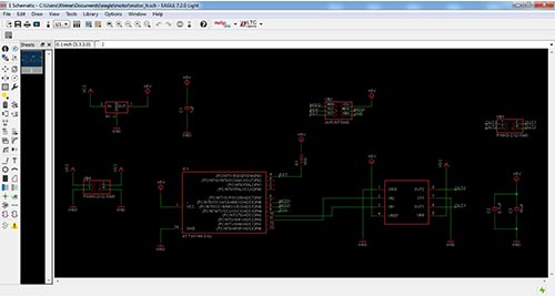
The prototype has had some errors that I will comment later, but is fully functional. Show below the schematic and board layout.
Eagle: Schematic
Eagle: Board
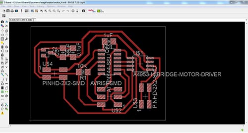
Board
Interior

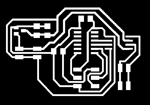
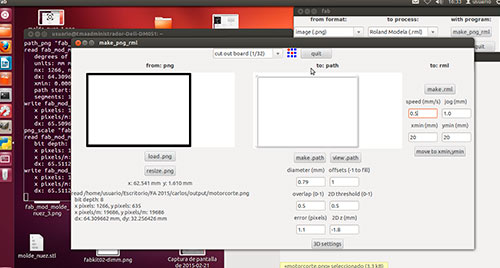
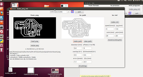
Once done the whole design is time to use Roland Model, for this I use the Fab Modules. In a first pass for the tracks and second to cut the edge of the board. After I perform solders for components.
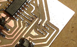
Traces
Interior
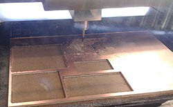
Modela machine working:
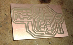
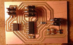
Board:
Some components:
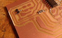
Board finished
Now is the time to program the newly created board. To do this I will use the circuit made weeks earlier, USBTiny. We connect both devices via the ISP, download the source code provided by the Fab Academy (hello.H-bridge.44.DC.c and hello.h-bridge.44.DC.make), in my case will perform the following steps in Windows 7 64bit operating system, started a system console (start -> run -> cmd.exe) and we place ourselves in the directory where you have downloaded files, then run the following command (assuming you have already installed AVRdude in above tasks):
make -f hello.H-bridge.44.DC.make program-usbtiny
If all it´s correct we can see on console:
C:\Users\Xtrene\Desktop\FAB Academy\Academy2015\motor>make -f hello.H-bridge.44.DC.make program-usbtiny
avr-objcopy -O ihex hello.H-bridge.44.DC.out hello.H-bridge.44.DC.c.hex;\
avr-size --mcu=attiny44 --format=avr hello.H-bridge.44.DC.out
AVR Memory Usage
----------------
Device: attiny44
Program: 322 bytes (7.9% Full)
(.text + .data + .bootloader)
Data: 0 bytes (0.0% Full)
(.data + .bss + .noinit)
avrdude -p t44 -P usb -c usbtiny -U flash:w:hello.H-bridge.44.DC.c.hex
avrdude: AVR device initialized and ready to accept instructions
Reading | ################################################## | 100% 0.04s
avrdude: Device signature = 0x1e9207
avrdude: NOTE: FLASH memory has been specified, an erase cycle will be performed
To disable this feature, specify the -D option.
avrdude: erasing chip
avrdude: reading input file "hello.H-bridge.44.DC.c.hex"
avrdude: input file hello.H-bridge.44.DC.c.hex auto detected as Intel Hex
avrdude: writing flash (322 bytes):
Writing | ################################################## | 100% 0.49s
avrdude: 322 bytes of flash written
avrdude: verifying flash memory against hello.H-bridge.44.DC.c.hex:
avrdude: load data flash data from input file hello.H-bridge.44.DC.c.hex:
avrdude: input file hello.H-bridge.44.DC.c.hex auto detected as Intel Hex
avrdude: input file hello.H-bridge.44.DC.c.hex contains 322 bytes
avrdude: reading on-chip flash data:
Reading | ################################################## | 100% 0.32s
avrdude: verifying ...
avrdude: 322 bytes of flash verified
avrdude: safemode: Fuses OK
avrdude done. Thank you.
When all is finished and connect the motor and battery for operation of output device, ... ohhh, does not work. The motor does not move, I check with the help of a multimeter output motor driver, and get values ranging between -4.90vy 4.90v, I put a couple of LEDs on a breadboard (with the pin in reverse order) and connect them off the board, the LEDs light up simulating the motor direction, obeying the loaded program.
Motor Driver + LEDS from Carlos Cano on Vimeo.
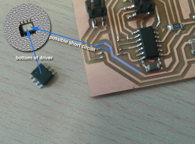
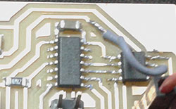
The brightness of the LEDs is faint, I have a problem with the power output. My instructor, Nuria, explains that the motor driver has a small plate underneath and can be shorted to one of the tracks that pass bottom. I have to remove the motor driver, delete the track that goes under and bridge with a cable connection withdrawal.
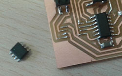
Unsoldering:
Removing the track:
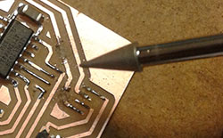
Removing the track:
Bridge:
After completing these steps, I see again the functioning of the board getting the same effect.For finish the task I placed an engine that requires less power to operate and thus the result is correct. (I lack discover what causes the loss of power).
Testing output motor from Carlos Cano on Vimeo.
Files: