Stage 1
ECG
ECG
My final project will collect data from different sensors and will show
the data on a special suit. These are the main features:
1.- All the data will be captured by Arduino sensors.
2.- The data will be: Heart Rate, Body temperature, Stress (measured
by heart rate variability), speed, Anaerobic threshold, Sweet, and so on.
3.- All these data will have a color code and the suit will change
the color because of the data acquired.
With this suit, you will see how the t-shirt change its color due
to hear rate, or how fast your friend ski.
After some electronic assignments and check the time it take in each,
now I realize that my project can not be carried out in few weeks. For
that reason I decided o simplify it.
Here it is my project updated:
This is the new proposal. Just one measurement and just one visual feedback. Here it is the presentation.png, scroll down for further information.
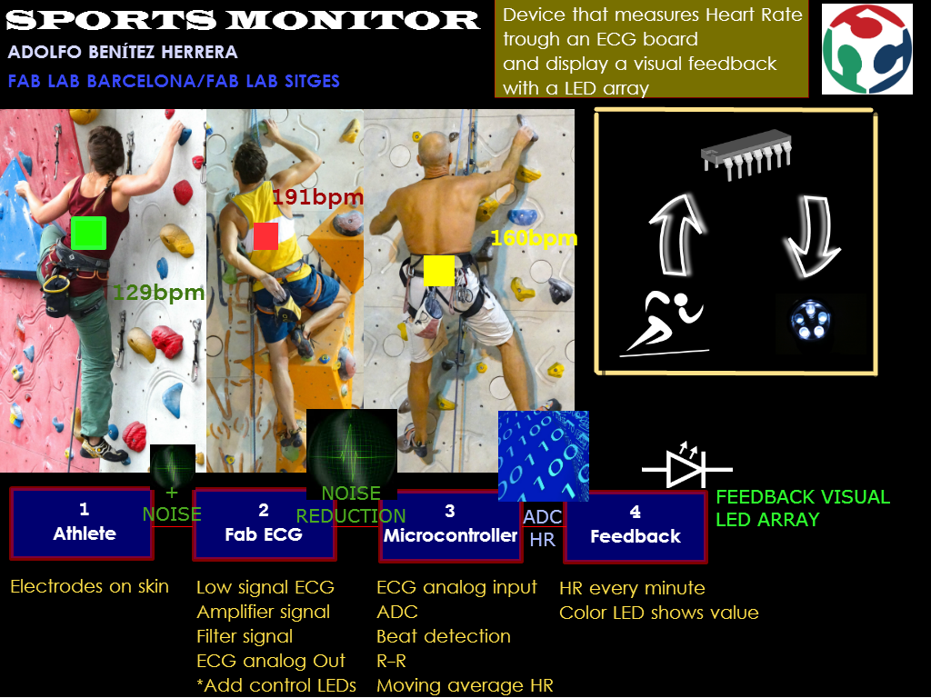
What will it do?
It's a weareable that could be attached on any t-shirt or cap. It will
collect the values of Heart Rate (HR) and change the color of an LED array
by value.
Who's done what beforehand?
There are three main part in my project:
1 Data acquisition
2 Data processing
3 Data Visual feedback
Let's talk one by one:
1 Data acquisition.
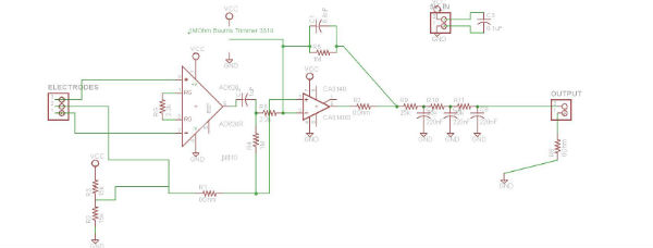
After some internet research and many DIY proposals, I decided to start
from Adam Marblestone FabECG. I think his work is easy to undestand
because is well documented.
At the moment of write this, I see some important changes that need to
be done: First the three low pass filters. I seems to be designed for 60Hz
US electrical power noise. Second some feedback LED. And third, a battery
suply.
In this stage, it will be acquired a 1mV ECG signal with electrical noise
and it will be sent a 1V ECG with noise reduction.
2 Data processing.
At this stage, I need to detect Heart Rate (HR) from 1V ECG signal. For
this purpose, I will introduce a microcontroller into the FabECG that do
the analog to digital convertion and detect the HR.
Many options to detect HR from an ECG: Voltage threshold, Fourier Transform,
correlation with the essential ECG graph, wave lets, and so on... Voltage
threshold seems to be the easy one, but any electrical noise or ectopic
beat could send an error. About Fourier Transform, I would use Fast Fourier
Transform (FFT) that is an algorithm to compute the Discrete Fourier Transform
(DFT). DFT converts a finite list os equally spaced samples in time domain
function to a finite list of coefficients combination of complex sinoids
in frequency domain. FFT option seems to be better, but we will see if
it's possible to compute it in few days.
I have found some nice tutorials about FFT and attiny:
http://shin-ajaran.blogspot.sg/
http://www.arduinoos.com/2010/10/fast-fourier-transform-fft-cont-6/
In order to avoid aliasing, it's needed to apply the Nyquist-Shannon sampling
theorem, that set the minimun sample rate which permits a discrete sequence
of samples to capture all the information from a continuous time signal
of finite bandwith (it means that no actual information is lost in the
sampling process). At arduinoos part 6 there are some important advices.
3 Data Visual Feedback
The visual feedback have to be easy to see and understand, so an LED array
with 3 colors could be a very nice option. In order to keep it simply,
I would do it with Carlieplexing method, that allow to manage several LED
with few microcontroller pins. The ecuation between pins and LEDs is:
L leds can be driven by=(1+sqr(1+4L))/2
So 4 pins can drive12 LEDs and 5 pins can drive 20 LEDs.
What materials and components will be required?
Let's talk one by one
1 Data acquisition
(First process iteration). I will order an digital potentiometer to try
autoadjustment second amplifier.
2 Data processing
3 Data Visual feedback
4 Connections
5 Packaging
Where will they come from?
The electronic stuff from digikey
Vinyl and Methacrylate from local distributors
Other stuff from corner shops
How much will it cost?
Between 30 and 40 €
What parts and systems will be made?
All the electronics and packaging. The electrodes, battery cage will be used commercial ones.
What processes will be used?
3 iterations. First iteration will be do everything as simple as possible, compying all that parts that already works. Second iterations will be change one by one those parts that could be improved. Third iteration will be redisign everything to set the final version of all parts.
What tasks need to be completed?
Redisign the FabECG in order to: 1st, change de cutout frequency to avoid
50Hz eurpean power energy (instead of 60Hz american one). 2nd, do a autoadjustable
potentiometer.
Redisign the array LED to set 6 row leds driven by 5 pins
Recode the charlieplexing code to manage the LED array
Code o adapt code for a FFT of ECG signal, in order to detect the Heart
Rate
Design the package
Design how to attach it to a athlete.
What questions need to be answered?
Is possible to do a FFT with 8 bits microcontroller (ATtiny44)?
What is the schedule?
Hopefully 1 iteration per week.
How will it be evaluated?
Detect the Heart Beat or the Heart Rate, is the main point. If is possible
to do it, is possible to finish the project.
Other parts, seem to be able to resolve.
Removing 60Hz noise
Nowadays, coexist two configurations of voltage and frequency worldwide
to transmit the electric power:
230V with 50Hz and 110 V with 60Hz. There is no technical reason
to prefer one over the other.
At US is used 110V and 60Hz configuration, at Europe is used 230V
with 50Hz configuration.
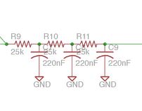
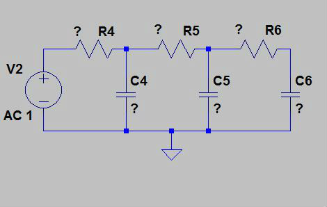
Now, if you read the Fab ECG tutorial, it has a bank of three low-pass
filters after amplification to remove additional 60Hz noise. In Europe,
the electric power noise is at 50Hz, so I decided to recalculate the bank
of three low pass filter to remove that noise.
One RC low pass filter configuration is a passive filter with cutoff frequency
fc = 1 / ( 2piRC ) . If multiple filters are chained much more selective
filter is achieved.
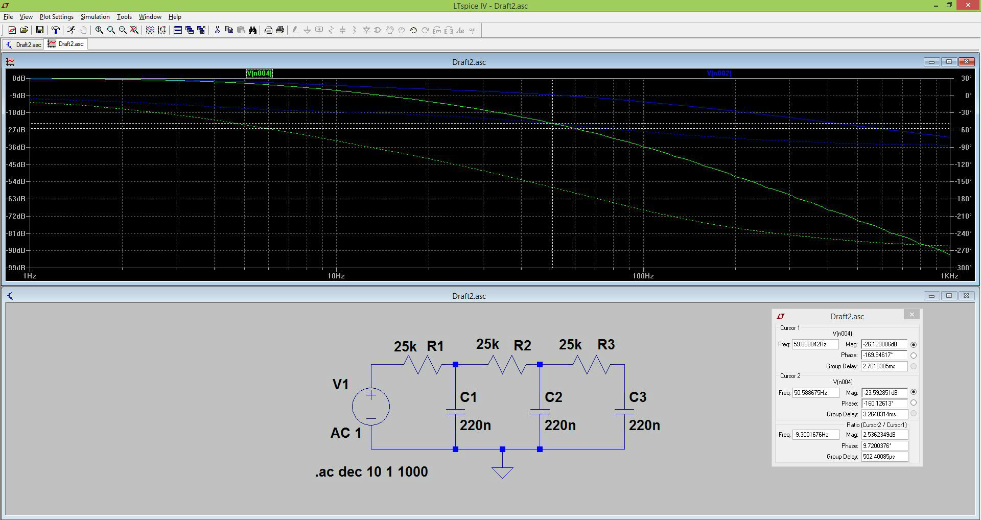
We can see a simulation of these bank of Low Pass Filters in the next
picture. We can see that:
- Between 50Hz and 60Hz there are -2.5dB.
- At 60Hz there are -26.12dB and at 50Hz there are -26.1dB.
So, I will redesign the filter to obtain -26dB at 50Hz.
In order to make a Low Pass Filter, we can use any pair RC values they
meet the equation:
fc=1/(2piRC)
Where:
fc: Cutoff frequency
R: Resistor value
C: Capacitor value
Considerations:
1.- The cutoff frequency (fc) occurs at resonance circuit RC , or what
is the same, the values of resistance (R) and capacitive (Xc) reactance
are equal.
R=Xc
And Xc=1/(2pifC), Xc value depends on frequency.
2.- Capacitor should not be polarized or high value, as they often have
higher internal losses and tolerances capacity that subsequently result
in a lack of accuracy during operation. For this reason, capacitors are
typically used by the nanofarad between 1nF and 680nF have a fairly wide
selection margin . Note that these filters often work in low frequency
between 20Hz and 20KHz.
Non- electrolytic capacitors have better performance in high frequency
than electrolytic capacitors.
3.- To minimal electrical losses, the output impedance of the signal should
be insinificant in comparison to the imput impedance (voltage bridging).
Zin>>Zout. So we need to know the Zin of next stage to be accurate.
That's because we could work in two situations:
a) We wish to to transfer maximum power and minimize power
losses by reflections from the load, if both sides are linear we
have to match impedance: Zin=Zout. (No, this is not our case)
b) We wish to transfer maximum voltage, instead of power,
then Zin>>Zout. (Yes, this is our case!)
Charles Fracchia and Adam Marblestone FabECG Week4 Fab Academy 2012
Charles Fracchia and Adam H Marblestone, have made an Open Source ECG
as a part of a collaborative effort between MIT and Harvard Medical School.
I have followed the tutorial of Adam Marblestone week5.
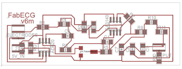
First I got all the documents:
Components List
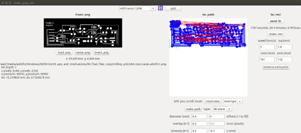
To see how to use Modela and Fab Modules, visit my
week4 Electronic production.
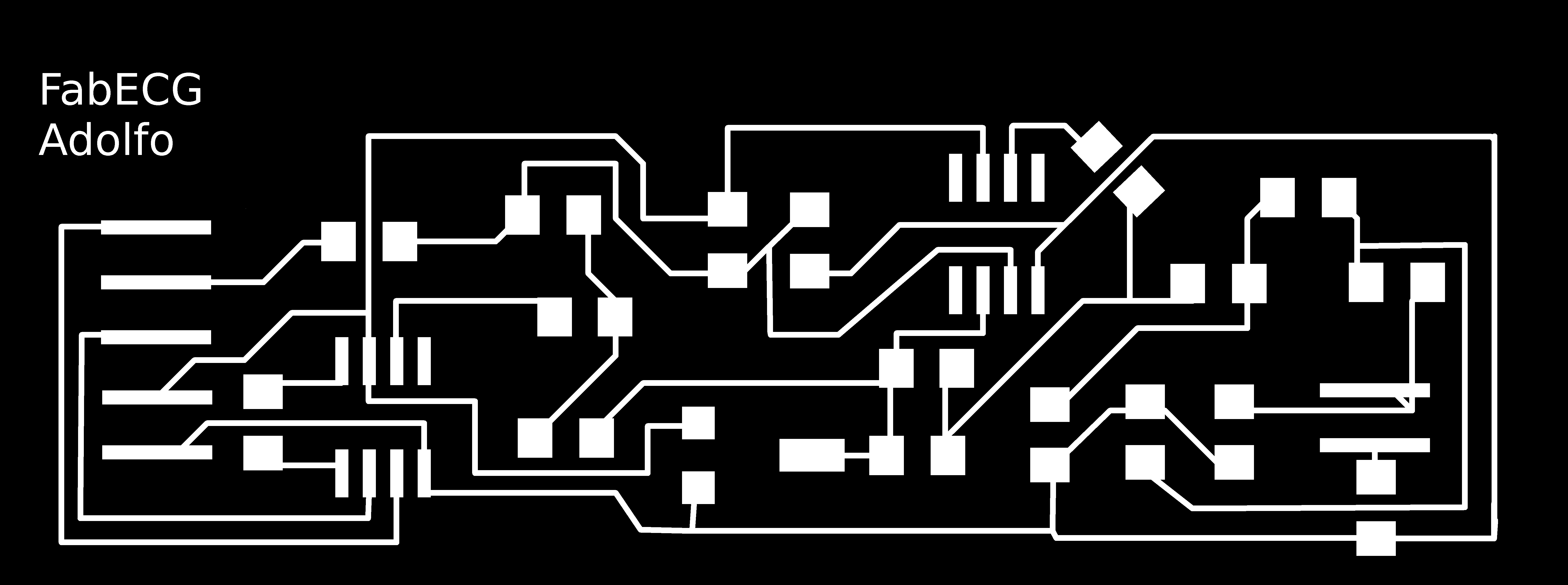
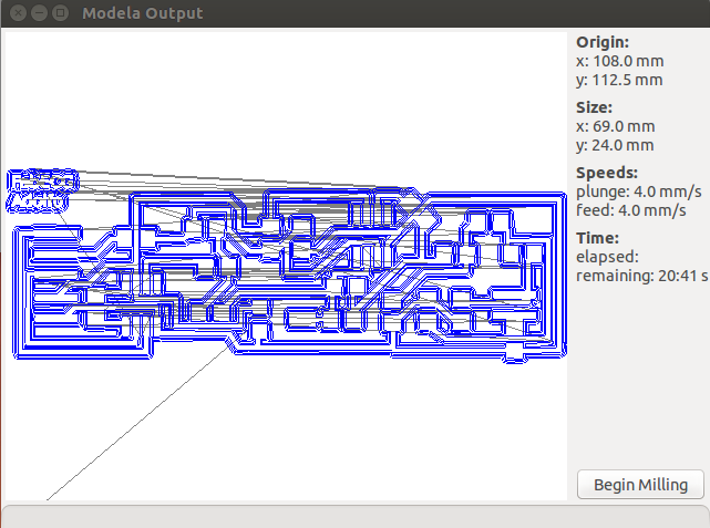
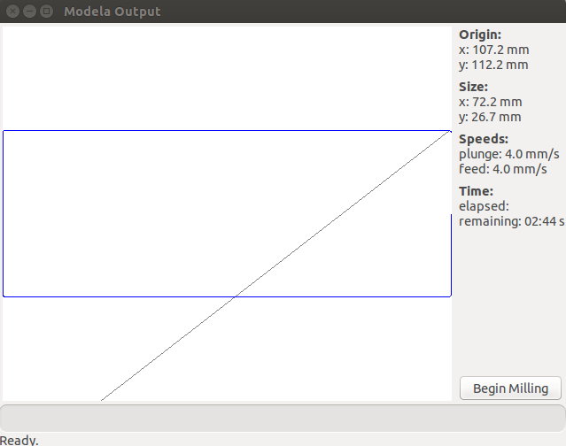
20mins 41 seconds for milling the PCB traces and less than 3 min to cut
out it.

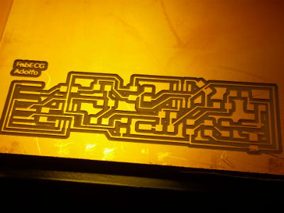
After milling, still in the modella.
This is the second try, the first try there were many traces not
milled, probably because the board wasn't flat enough.
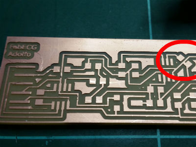
I checked all traces and I discovered two traces not well milled. It have
to be repaired with a cutter. Let's do it!
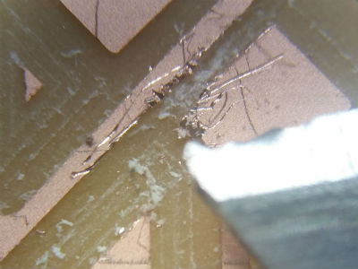
This is the microscope view after reparing the traces. It seems to be
ok, now.
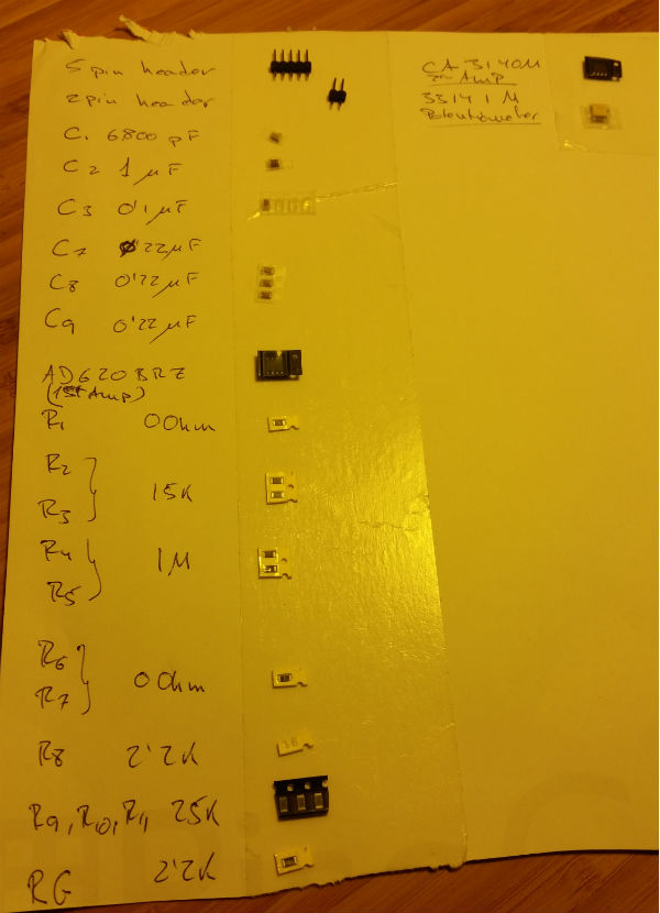
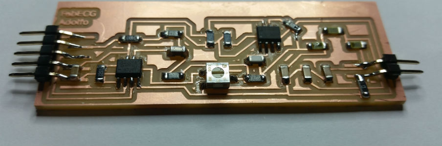
I'm used to make a list of all components in a piece of paper and with
double side tape, attach all components prior to start soldering.
This is a good trick from Ferdi (BCN Fab Lab at 2015)
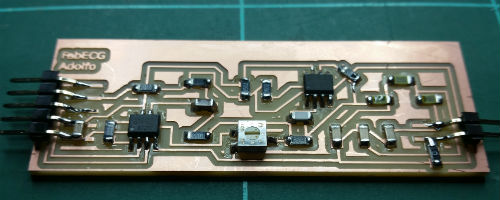
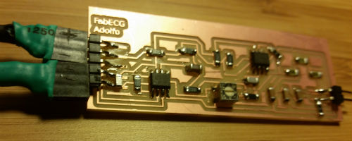
This is the final PCB soldered with all components on it. It looks nice...
There are many connections to do:
Clips for the electrodes (I will use commercial electrodes because according
to Neil, could be a nightmare project if I try to make my own electrodes.
ECG signal is 1mV signal, so any noise on electrodes will cover the signal.)
Cable electrodes to FabECG.
Connections to FabECG.
Battery case. I will supply with 5v battery case.
The Electrodes will need a female header for connect with FabECG
After solder the 3 pin connectios, seems to be too close to each others.
So I will cover the central pin to avoid short circuits
A little piece of plastic tube to cover the central connection
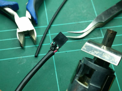
To make a protection for the central pin I have used:
Tools:
Plier
Hair dryer (electronics especific)
Tweezers
Material:
Plastic tube
I opened the plastic tube, cover the central pin, and finally hot air
from the hair dryer to adjust the plastic connector.
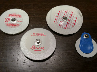
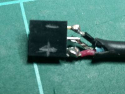
This is a commercial electrode for ECG. I got many of them from many different
brands.
All of them have a "clip" connection. So, next step is to make a clip
connection between electrodes and FabECG.
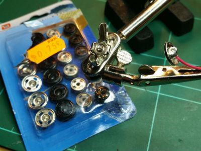
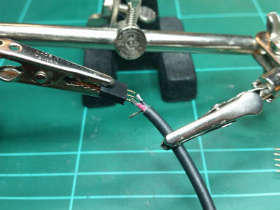
From a corner shop, I got some clothes clip and solder them to the electrodes
cable.
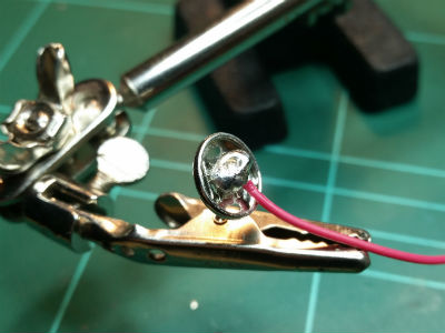
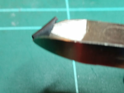
To adjust the clip to the electrode, a little piece of metal have to be
free in order to make the "clip" action. Many times, when I used tin to
solder, it solder this piece of metal, doing impossible to do the "clip"
action.
I had to make several attempts in each clip until welding wire firmly
and free clip.
FabECG connected to battery case cable and electrodes cable
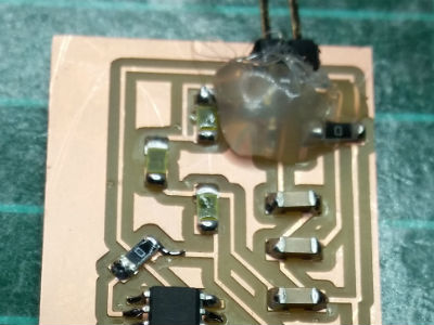
After some test, the FabECG has need some reparations on headers. That's
because the FabECG it will be portable and those connections are not prepared
for movement.
Yes, I know... You don't need to say to me.
It's a shame!. It was very nice the FabECG before putting silicone,
but I need further testing without having to continually repairing.
It doesn't work yet... may be is the moisture of human sking under my t-shirt?? Mmm, may be.
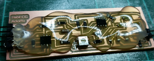
Yesssssssssss,... It's getting worse, isn't it?. Why that? Well,
I decided to destroy the nice image of my old "nice FabECG" because is
in continuous contact with human skin and may be this make some unwanted
connections. Hopefully, my final project will have a better case look.
Lol!
Adolfo is alive, it works!