Mechanical Design Class
16th Worldwide gathering for Fabacademy 2015 feat. prof. Neil Gershenfeld
- Access the content mechanical design and machine design
- Watch the class video
20th May
to 22nd of June
Weeks Work
For this weeks work the 16th Assignment of the 2015 edition of FabAcademy will culminate into Groups task with total duration of two weeks plus a few deadline postponing. So here at Sitges Fab Lab, after class we got all together for brainstorming on what our goals should be and what should be the final machine.
Several ideas came to the table but non of them seamed reasonable enough at this early stage of the assignment. So we started by defining the level of axis complexity that we wanted to achieve with this machine and worked from there.
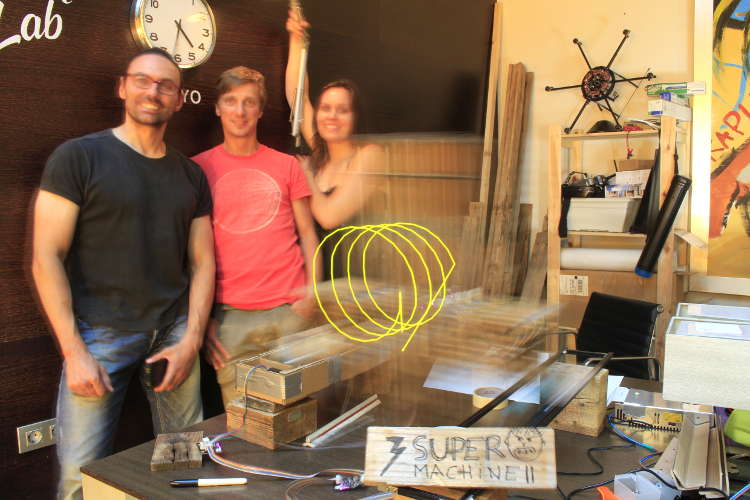
Defining 3 different axis machine was then our goal so we started dividing tasks. Being three people now at the Lab made the task dividing easy. That being:
- Design Readjustments - Maria Bento
- Electronics production - Adolfo Benitez
- Gestalt nodes and programming control - Anders Haldin
Despite of the assignment division we all agreed on switching from time to time so we could all have an idea of the different working processes required. At the same time it was important to set the schedule in the way we could work as a group and still have some free days to work on our Final Project.
1st task - Adjust Stages Design to machine and materials + Mill boards + research Gestalt
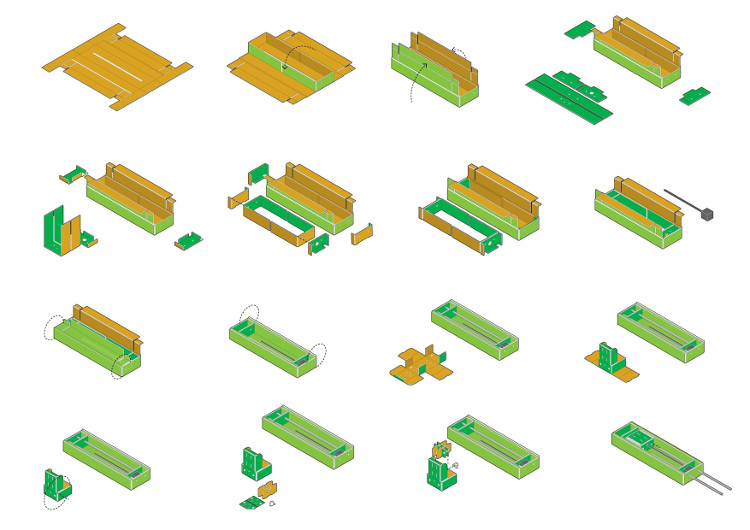
First of, while Adolfo was producing the hardware needed and Anders was getting power supply ready and checking the Gestalt requirements, I got the first look at the designs available from Nadya Peek's Github and Documentation Page 1 and Page 2. The files I needed for the Design where a Rhino model with available grasshopper parametric file customizable features. For the first stage box we used Nadya's original design readjusted to our machine size (limits 20x12 inch and did a test cardboard stage using our own cardboard thickness - 3.15mm
2nd task - Producing the Stages + electronics and Power supply ready
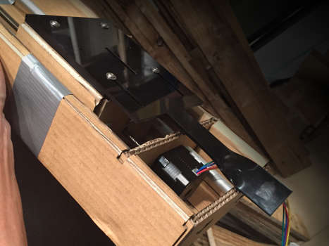
We had a few problems regarding designing and Lasering that you can check on Maria's Page but once those were fixed and custom we could start folding, assembling and gluing the 4 available stages we received each with their stepper motor + integrated lead screw on.
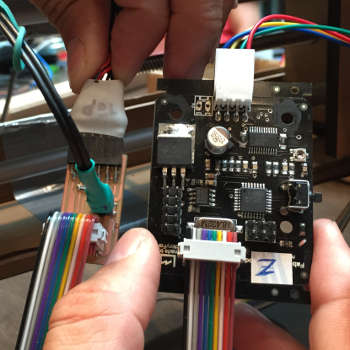
At this point the Fabnet USB board was milled and stuffed, power supply and Gestalt info were ready and understood. Check Anders's Page for more detailed info of the process.
3rd task - Networking 4 stages + Testing singular nodes
After connecting a gestalt to each of the 4 stepper motors + integrated lead screw we got the chance to check them individually and then identifying each node when networked. One of the Gestalt nodes was giving us warnings saying "could not reach virtual node" error while it was apparently "Running in booth loader mode" so some debugging and to be done - check it on Ander's Page on Friday 22nd.
After a few emails exchanged with Nadya we had use some of the code available on her Github to flash that node again and it after a while it was responding well just like the other 3.
4th task - Designing and Producing End-effector
At this point other ideas came to mind and Maria suggested that since our Lab is at the beach the end effector could be a~portable drawing tool used to draw in a sand surface. The group was happy with the idea so we decided to keep that one for this assignment.
This was an machine idea inspired on 2014 Israel Pavilion at the Venice Bienal that uses the working axis system of a regular CNC machine with a needle tool as end effector to draw maps. Our improvement to this would be its portability. And with that the possibility of doing bigger designs.
We ended up designing a flattened end-effector to be used as a "calligraphic pen" that could be attachable to the existing holes on the machines moving part. For that we used Rhino as software for the design and laser cut the designed shape on black acrylic. For a more dynamic effect of calligraphy Anders had the tip twisted with the help of heat gun. This process was preferred to 3D printed version that we had previously considered and later dropped for a question of timing and eventual risk of recurrent failure as it was a big and thin piece to print.
This is the final result. For design process visit Maria's Page
5th task - Building machine according to desired function
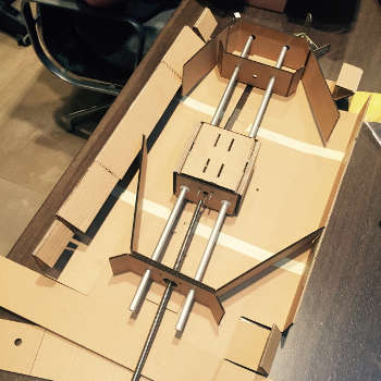
For this drawing machine we built a 3 axis machine with four stages, keeping it's modularity characteristics at every cost. We have two stages driving the X axis, a third stage placed 90 degrees over the first two for Y axis and then we would attach a 4th stage vertically to the Y axis to move up and down the Z axis.
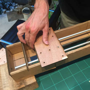
To keep the machine modular we added a few wooden platforms with matching holes to the base and the moving parts of the stages. This way we could easily attach or remove each stage.
At this moment a lot of questions and failures where being reported on to the class email and not so long after we got news from Maximo who had a tutorial on how to automate the machine via wxGestalt.
6th task - Testing and Debugging
All stages were assembled and working individually was when we tried put them all to work with the wxGestalt that we realized there was still something not right.
First warning with the following WxGestalt python ERROR
global name base not defined
And that was recurrent in the following cases, when:
- Nodes AR + Y = working!
- Removed x seems to give connection problems
- AR+Y+Z= working fine!
- just X node= is working fine
- Swapped order of the nodes recheck all cable positions= Same connection errors when all the 4 stages are wired
- X + y + AR= 3 axis working fine
- X + y + AR + Z= could not reach virtual node
Conclusion 3 axis work fine, 4 axis don't work ever. After this long serious debugging, we concluded using WxGestalt was not going to be a success so we had to change tactics.
3axismachine from Anders Haldin on Vimeo.
7th task - Reaccessed evaluate time and target goals
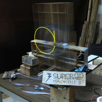
As two of the stages were actually performing the same motion and task we decided to reduce the actual number of stages to just 3 and replace one of the physical stages by a slider to be placed parallel to the remaining X axis were other extreme of Y could slide on a dolly built of metal rails.
It was getting late on schedule and late at night so we had the idea of simplifying the machines end-effector and outcome.
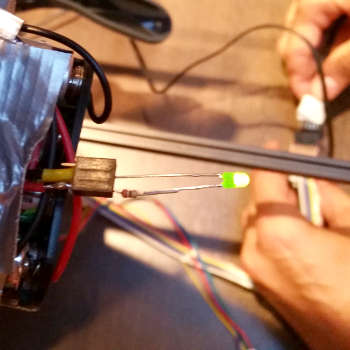
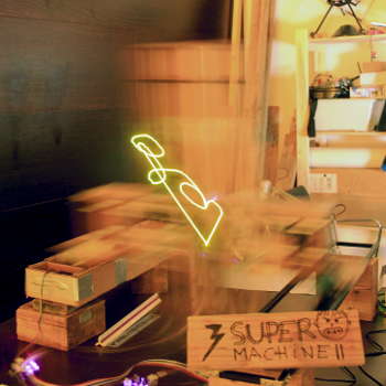
We decided we would have a Light machine that would draw using a LED end-effector and coordinates that we would be hard code into the initial python script.
8th task - Designing mathematical coordinates for hard coding
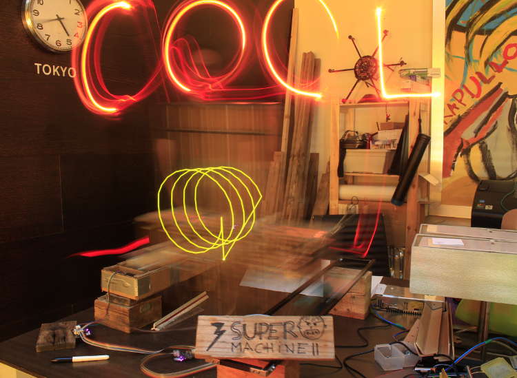
For the actual design Adolfo started arranging a list of the necessary coordinates using a mathematical approach. Via Excel he would plot point by point defining a circle by equally distance points using Sin & Cos then we would hard coded and record it with a camera using light exposure mode. On the second try we added volume to the shape by building a spiral where gradually the circular sequence of points grew in Y axis direction. These are the results we ended up with.
9th task - Designing parametric slicer for hard coding
Very happy with our finally working machine we kept experimenting with light drawing and Maria remembered that we could try designing any other shape in Rhino and extract the coordinates using a grasshopper. That would mean defining a one line drawing and later using the divide curve component that would divide that line into a reasonable amount of points later extracting them by using a panel view.
The only trouble we had it was that the "OLA" word she wrote appeared to be reflected so we figure out it should just be the location of the drawing that was wrongly placed in the Cartesian space.
10th task - Documenting Final Results
Successes:
- Getting a working, 3 axis light painting machine and have pictures to prove it.
- Fixing broke board by fusing and re flashing it.
- Having a modular design for easy assembly and transportation.
- Doing parametric design through Rhino and grasshopper and outputting coordinates to python script.
Failures:
- Machine only runs by being hard coded. We never figured out how to get it to moving "live", controlled through a interface like wxPython.
- The machine design it self is modular, but it is not very steady.
- We could not get it to work with more then three gestalt nodes, it never registered the fourth.
Questions?
- How can we add and communicate with a ATtiny 44 board in the gestalt network? This would be great for controlling the color and intensity of the LED?
- How do we changes speed of the stepper motors?