
Final Project No.4
Electronics Design and Programing
This section is for my electronics design and construction.
Abstruct
Below figure is block diagram of this electronics system.

Main partd are DCmotors, micro computer PCB, motor driver PCB, neck motor.
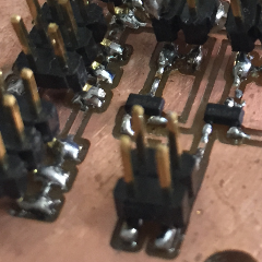
Make Main PCBs
Micro computer PCB is based on network assignment board. But not absolutely same.I removed resonator because I want to use resonator port for IO.

Board's circuit pattern data is here.
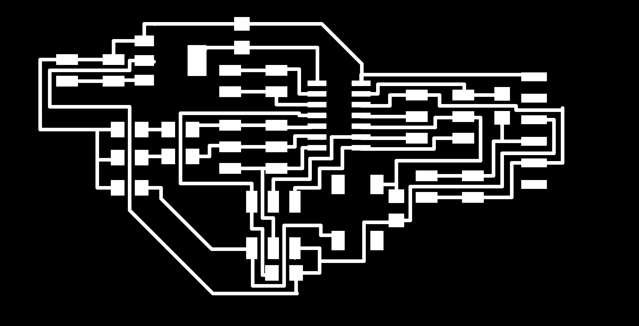
Board's outline data is here.
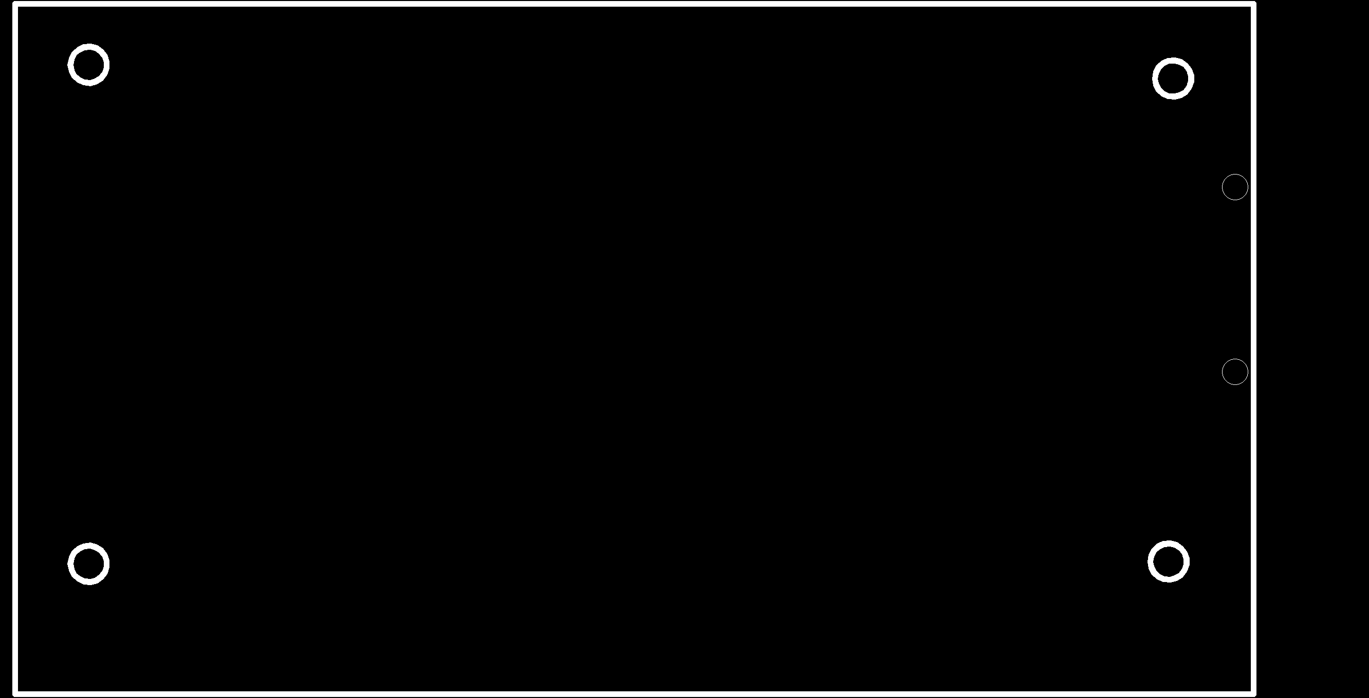
. There are Eagle data. sch and brd.
Make Driver PCBs
Motor driver PCB is made from N-MOSFETs.This gate pin is connected to ATtiny44 and be driven PWM.

If Board's circuit pattern data is here.
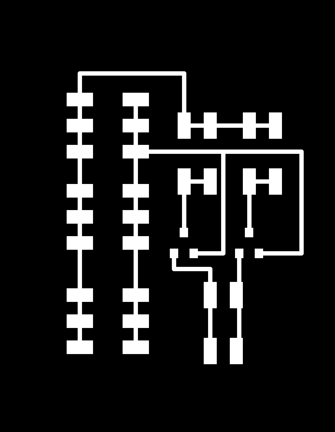
Board's outline data is here.
. There are Eagle data. sch and brd.
Make Encoders
I decide to make encoder by own design.
This encoder is "CNZ1023(ON1023)". Circuit is usually used like below datasheet diagram.

I found additioal information from This website.
. So, I change resister value 50 ohm to 100 ohm, RL to 100k ohm.
Switches
I used rotary switch.This switch has 12 pin and it can choice one pin and connect.
So, I solder different resister to 12 pin eath other. ATtiny44 that is on Main PCB can detect voltage level "analogRead"command.
Therefore, Main PCB can select 12 pin using only 1 analog IO pin.

Then, Pin-layout of ATtiny 44 describe in below table.

Programing
I program Arduino ISP.
But I had have many many problem. So one of functions is incomplete.
For example, servo motoer for neck angle coudn't move. Becaouse, servo library can't use with other PWM signal for left and right motors . Other point, encoder could detect slit of encoder disk. I wanted to use this count for knowing the advanced distance.
But I couldn't finish all tasks.
So, I only completed below functions.
1. I can select advanced distance using rotary switches.
2. Left and Right tire speed can change eath other.
Program can read here.
. The lastest pin-layout is below table.
