
Assignment Week10
Input Devices
This week’s assignment is "measure something: add a sensor to a microcontroller board that you've designed and read it”.
I tried to make step response sence board.
Why step response sencor can sence?
There are many kind of step response method. In this case I choice capasitive touch sensor.
Capasitive touch sensor can detect human's touching finger.
This circuit needs very high level resister. And something conductive material.
This method is famous by Arduino's library.
If we use this library, high level resister must be connected send pin and reseive pin.
Receive pin must be connected something conductive material too.
When human touch conductive material, capasity level change.
In this case, finger is conductive too. Then, capacitor is made by finger and conductive material.
This capacitor can charge electricity. Charge level is belong to distance of finger and conductive material.
So Charge time is change, too.
This sensor program detect charge time, calculate, and know that finger is touching or nearing.
This technology is used by iPhone. I have learned about basis of most familier technology.
In this method, It use two pin of ATtiny45.
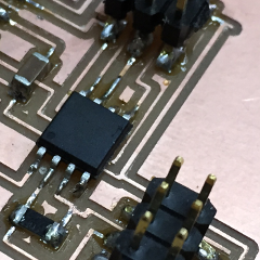
Making PCB
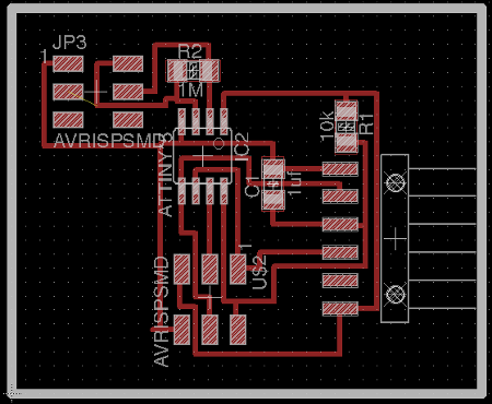
I made PCB board for step response.
It's own layout. But circuit design is based on Neil's data.
And, Emma's Presentation PDF file.
Board's outline data is here.
There are Eagle data. sch and brd.
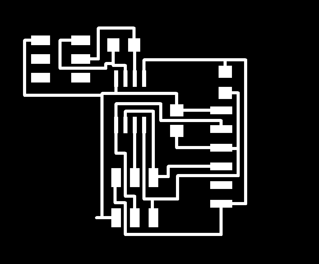
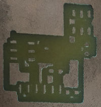
When I make this data. I mistake. It is about what exporting circuit data by eagle.
When I have completed circuit data, I exported png data of circuit.
Eagle's export command is "File > export > image".
Then, new window about export setting appear .
Usually, we select "monochrome" and resolution number must set higher than 600.
But in this assignment, I didn't input resolution number.
So, I export default resolution png data. (150!)
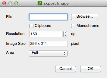
This is wrong !!
Then I milled very dirty PCB.
Almost pattern line wasn't remain.
I retried 3 times.
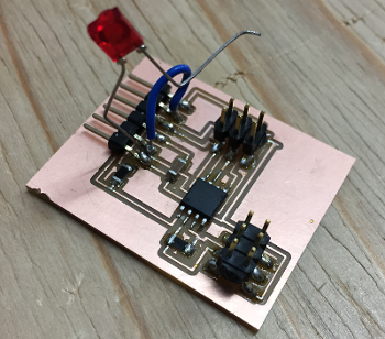
I completed at last. Next, solder parts.
Cathode of LED soldered on this PCB' GND. This is my original. To check my Touch.
LED' anode pin is free. because, ATtiny45's output pin is used for connecting AVR Wrighter too.
If I solder LED's anode pin to ATtiny45, I can't write program to it.
So, I connect anode to header pin by hand after writing program.
Send Program and execute
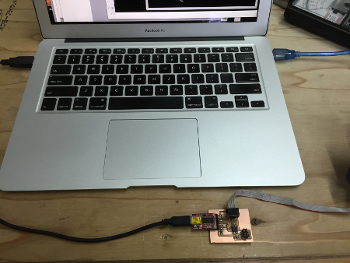
I connected and transport program from PC to PCB. I use Arduino IDE. Program is here.
I connected touch board to pin3 of ATTiny45. It's made by material of PCB.
Then, I supplied power to PCB. When I touched touch board, LED flickered.
Complete !!