Assignment Week2
Computer-Aided Design
This week's assignment is modeling a possible final project, and posting it on own class page.
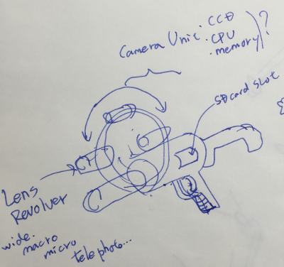
The sketch that have drawn about my Final project last week is drawn as only inspiration and imagination.
So I tried to detail up my idea and drew 3D model.
Using Inkscape
I used "Inkskape". This software has many kind function for drawing vector data.
Mac version can be download here.
My last sketch about final project, has tree-dimentional shape. But part of revolver can be made as flat.
So I made it using Inkscape.
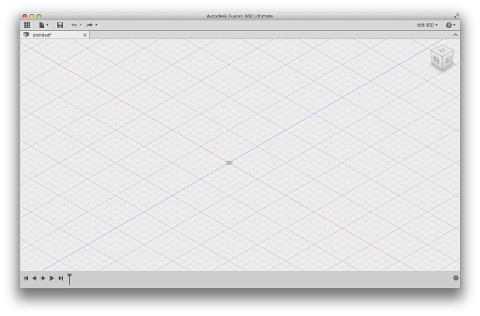
First, I execute Inkscape. below picture is first look.
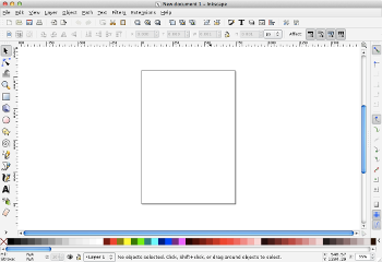
left side Icon is "mode select buttons".
revolver part has circle shape. So, I choice circle icon, and draw.
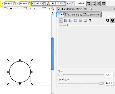
Shape's positon can set in top bar "x" and "Y",Yellow rectangle.
Shape's size can set in top bar "W(width)" and "H(haight)", green rectangle.
Shape's line style can set right box,blue rectangle. Bold line or thin line, fill in or not?
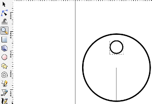
Add new small circle, and choice cursol icon. If Crick two time at small circle shape, apper the cross shape icon.
Drag the Cross shape icon to center of big circle. it is used next step.
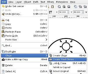
Select "edit > clone > Create Tled clones... ".
New window appear at right side.
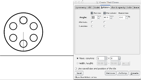
Select "sift" tab and check to "Exclude tile".
Next, select "rotate" tab and setting 'Angle'. In this case, number is 60.
And secect number of shape in "Rows Columns". In this case, number is 1 x 6.
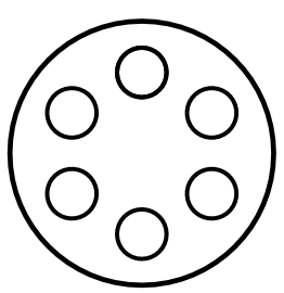
Complete !!
There are complete data. eps and svg.
Using Fusion360
3D design program that I usually use is Fusion 360. This is used for no sell.
This is similar to Solid Works. Because Fusion 360 and Solid works both have concept of “sketch" and “feature".
“sketch" define 2D shapes or cross section diagram, and “feature" define detail aspect of 3D parts that is defined sketch.
But, to be exact in Fusion360, "feature" is called "modify".
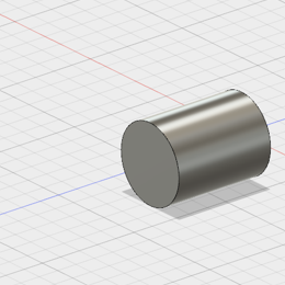
First, we make 2D shapes using "sketch". Next, select modify type and sketch that want to convert 3D.

Sketch mode button
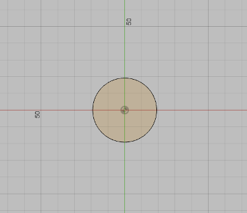
Sketch data

Modify mode button
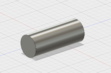
Modify data
Fusion 360 and SolidWorks is called "Solid modeling tools."
And another modeling tools is called "surface modeling tool", like Rhinoceros.
Rhinoceros define 3D things using surface.
Modeling My Project
I detail up my final project.
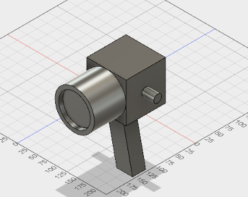
I want to make this camera that can imitation many shooting technics.I list up functions that I want.
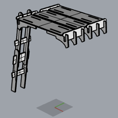
So, I build up like DIY camera mount. It can mount robot arm that using both sides projection
Next I use "joint" command. This is like "Assemble" command in Solid Works.
I have used this function at first, had very confused.
In case of Solid Works, Assembled materials is distributed as each other files.
But in case of Fusion360, I need to build up all materials in 1 file.
I make two or more divided parts, and change to components. So, I can use joint command.
Because joint command need to set two surfaces of other parts.
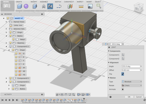
I made camera model with feature of rotate axis, and two link parts.
Feature of rotate axis is assembled with hole of link parts.
And I set "flip", "motion type", "offset number", and "rotete axis"
"Flip" define direction of assemble. "Motion type" is select of assemble type, like revolute, slider and more.
Offset number is distance between two surfaces, and rotate axis define assembled part. It is chosen from x,y,z.
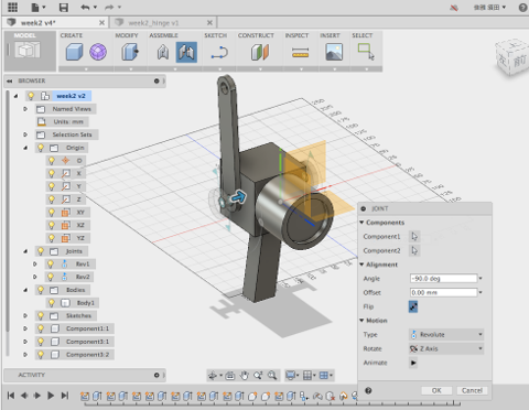
This link parts is grip to hold camera for robot arm or my hands.
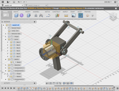
This data upload to Thingiverse. Go to here.
UPDATE!! : Using Rhinoceros and DraftSight
I used Rhinoceros and DraftSignt for Week8 assignment "makek something big"
I wrote "how to use Rhinoceros and DraftSight" in here.