
Assignment Week8
Computer-Controlled Machining

This week’s assignment is "make something big" !!
I have very important and serious limitation in this week.
Our "FABLAB Hamamatsu" don't have Big CNC machine !!
But, My instructor "Take" has bought it for this assignment.
And next Friday, It's delivered our lab, at last!
So in this week, I made only digital CAD data, and prepared for use CNC.
Detail of New CNC machine configuration:
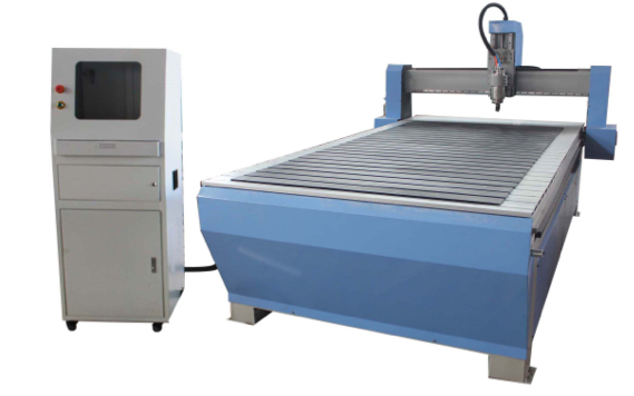
>Model : ZK1325
>1300*2500mm*200mm X,Y,Z working area
>3.2KW water cooling spindle
>450B model stepper motor and YAKO driver 2811 Aluminum T-slot table with PVC
>Taiwan HIWIN square guide rails
>MACH3 control system 5 axis
Sketch!!
What will I make ?
I decided to make roof-top bed of my mini cooper.
I want to sleep on this construction and make that can house in mini.
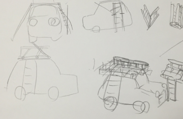
This is sketch about it.
This can make application of press-fit construction.
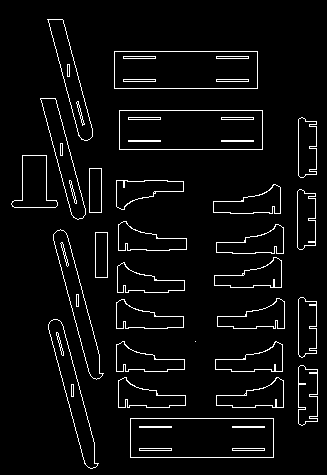
First, I draw sketch of it. This is composed two parts, Roof-top parts, and ladder parts
These are knockdown.
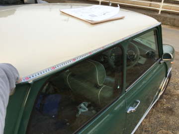
I measured scale of my mini.
Using Rhinoceros
I made model data of Rhinoceros. This is very famous 3D modeling tool.It's Japanese edition can download here. Windows edition is shareware, Mac beta edition is free.
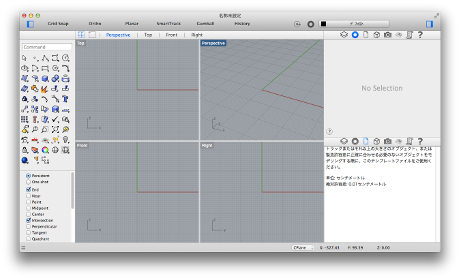 Rhinoceros window
Rhinoceros can make also 2D data.
So making step is,
1. Make 3D data.
2.Distribute and set out parts.
3. Convert to Dxf data, and edit or fix it.
1. Make 3D data.
Rhinoceros's 3D data is made by solid data and surface data.
If we want to make complexity model, should make surface data.
If we want to make Simplicity data like make solid data, first.
I used both data, solid and surface.
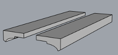 3D model made by curves and straight lines
In 3D model, press-fit area of two parts is made overlapping. And, use boolean operation.
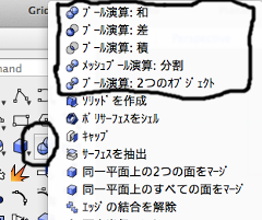 Commands of boolean operations
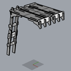 This is complete model.
2.Distribute and set out parts.
I moved these parts using mouse and command.
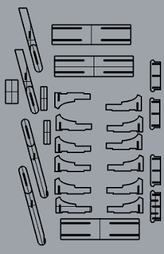 Set out parts
3. Convert to Dxf data, and edit or fix it.
In order to use CNC, I must make dxf data of it.
Rhinoceros ‘s command “MAKE2D” can convert 3D data to 2D diagram.
At No.2 step, I have set out parts. so when I have done this command, all part are converted 2D diagram.
Next, select 2D data and execute “select and export” command, and kind of file is dxf.
Then, dxf data and edit or fix it. because this dxf data was not complete.
For example, Rhinoceros’s boolean operation can’t make depth of press-fit area.
I used “Draftsight” for edit dxf data. Draftsight is used for free. but it need activation.
It can download here.
Draftsight can use like AutoCAD, so very useful and very kind for Professional engineer user.
Draftsight can use a lot of commands. It can be used graphical icons, or command line. I use "move" command from command line and mouse to make depth of press-fit area, and to layout belong to material size.
My deisgn file is here.
 Draftsight window
Using CNC!!
In march 28, FABLAB Hamamatsu Got Big CNC machine!
Very big, cool, and dangerous !!
Lab master Take had set up to use, I tried
 It can put 788mm×1091mm!!
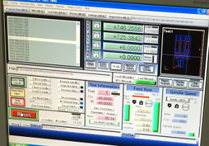
This CNC is operated by PC of below picture.
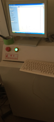
This PC have 2 software to make something big.
G-code generation soft "Cut2D", and operation soft"Mash CNC".
Make G-code
1. I import 2D data of Draftsight to Cut2D and setting parameter for milling.
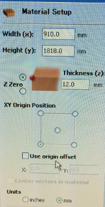
2. Setting material data, size, origin position, and units. I set like below pictures.
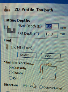
3. Click right-side tab"Toolpath", and setting toolpath data, about Z-axis depth,Endmill size,position with path data.
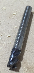
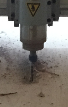
In this time, I use 6mm endmill.
If you want to use another size endmill, click edit button and edit parameter about mill-data.
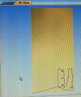
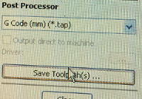
4. Check the layout and save toolpath that be made by G-code.
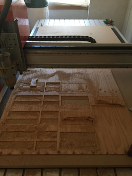
Milling
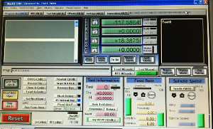 This is MashCNC
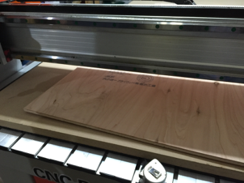
1. Setting material. In this time, I used T12 plywood board. Board must be aligned with base stage line.
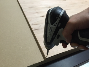
2. Fix the board with base stage using screw.
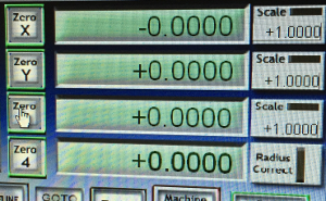
3. Set the ZERO point of work area. In this time, left side and near side of operator is ZERO.
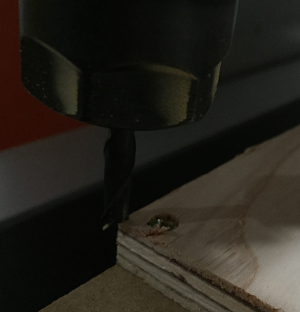
If I endmill move to ZERO point, I MachCNC's axis parameter set to ZERO putting button of "X", "Y", and"Z".
4. Import G-code file and check the path.
5. Execute!
But....I failed. Cutted surfaces is very dirty, and occurred heavy smoke.
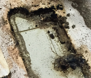
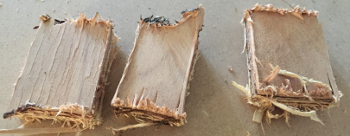
I thought about cause. This case have relation with speed of spindle speed and feed rate.
So I edited Cut2D parameter and made new G-code file.
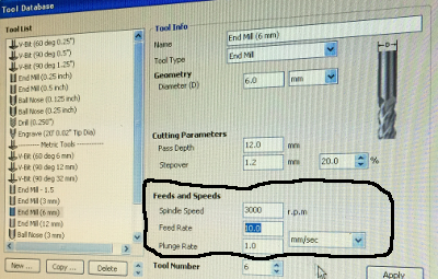
So, Latest Setting is...
> Spindle speed : Change, 13000r.p.m. to 3000r.p.m.
> Feed rate : Change, 15.0mm/sec to 10.0mm/sec.
> Tool : 6mm endmill (for metal)
> material : T12 plywood board
Then, I successd.I cutted all parts and assembled.
 Complete!!