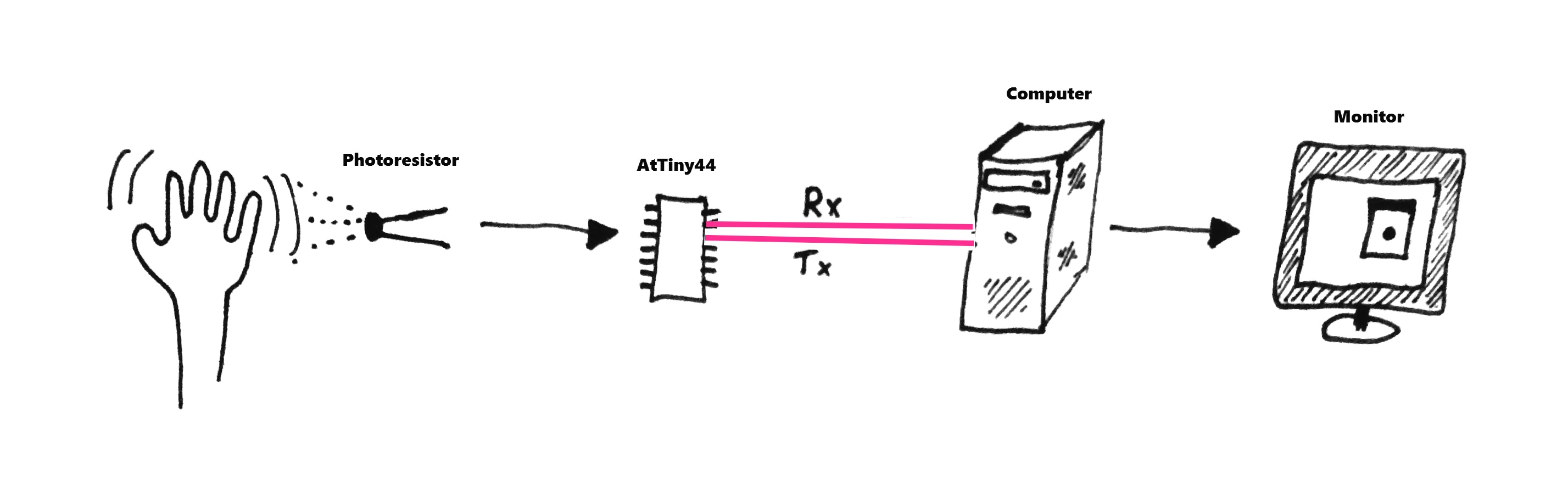
Interface is the way to communicate through the eyes of the user, on this assignment I will try to implement it and Program an Application that converts input to screen visualization.
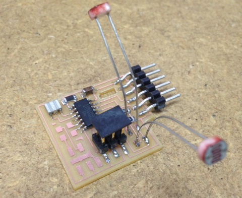
For this week I wanted to demonstrate an input from two photoresistors for my final project. I used a board that I made a few weeks earlier and programmed it to send the readings through the serial port.
Serial communication needs a special library for the AtTiny44 micro-controller. I used the SoftwareSerial.h after downloading the .zip file I opened the Sketch menu->Include Library->Add .ZIP Library and browsed to the downloaded zip file.
This is the code I wrote for the input controller. Using SoftwareSerial I declared pins 0 and 1 as Rx and Tx, pin 0 receives data from the computer and pin 1 transmits. The controller waits for a signal from the serial monitor and then reads the input from the two photoresistors and sends back the readings.
#include <SoftwareSerial.h>
SoftwareSerial mySerial(0, 1); // RX, TX on pins 0 and 1 of AtTiny44
int firstSensor = 0; // first analog sensor
int secondSensor = 0; // second analog sensor
int inByte = 0; // incoming serial byte
void setup()
{
mySerial.begin(9600);
pinMode(2, INPUT); // first photoresistor on pin 2
pinMode(3, INPUT); // second photoresistor on pin 3
}
void loop()
{
// commit readings when triggered by serial port:
if (mySerial.available() > 0)
{
firstSensor = analogRead(2);
// delay 10ms to recover:
delay(10);
// read second analog input
secondSensor = analogRead(3);
// send sensor values:
mySerial.write(firstSensor);
mySerial.write(secondSensor);
}
}
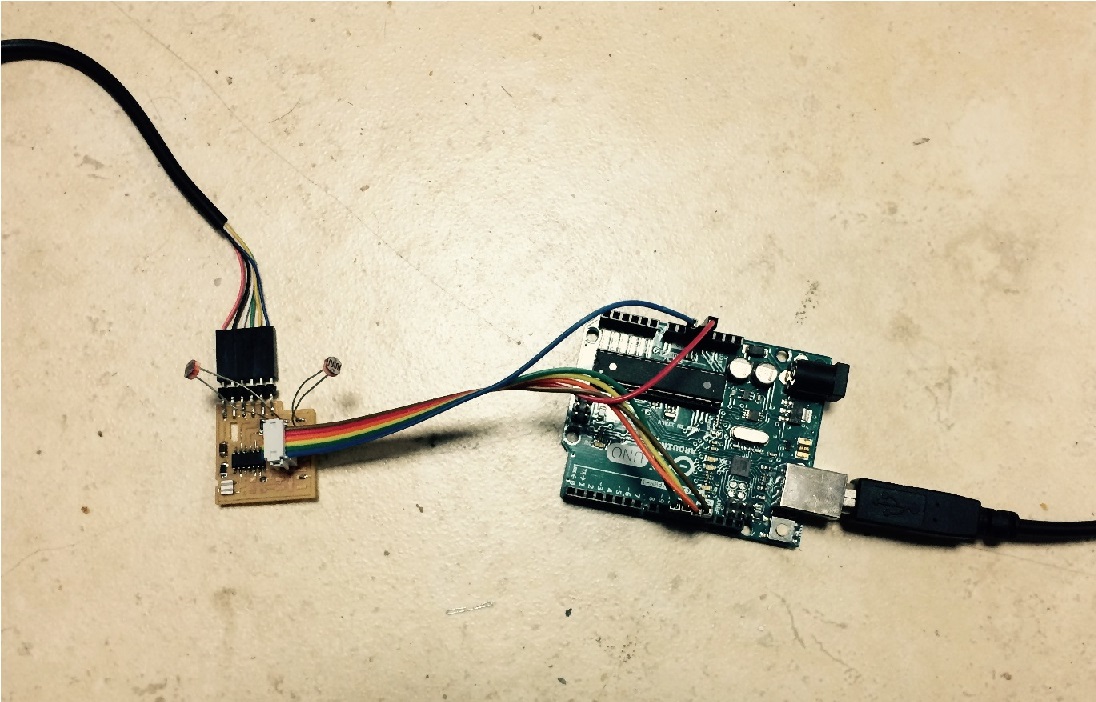
To program the controller I used Arduino as ISP. In the examples there is a program that I uploaded to my Arduino UNO. After I uploaded the code, I connected it to the 6 pin connector as written below.
// pin name: not-mega: mega(1280 and 2560)
// slave reset: 10: 53
// MOSI: 11: 51
// MISO: 12: 50
// SCK: 13: 52
// VCC: 5V: 5V
// GND: GND: GND
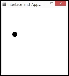
For the application that interfaces the input I used Processing. I found it very intuitive and easy to work with. The interface is very similar to Arduino and the code structure is also not so different.
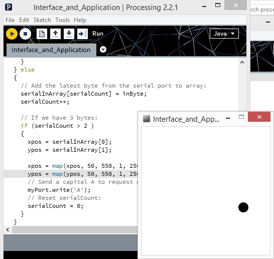
I wrote a code that draws an ellipse on the screen according to the input of both sensors. The first photoresistor determines the X axis position and the second photoresistor determines the Y axis position. This is the code.
import processing.serial.*;
Serial myPort; // The serial port
int[] serialInArray = new int[2]; // Where we'll put what we receive
int serialCount = 0; // A count of how many bytes we receive
int xpos, ypos; // Starting position of the ball
boolean firstContact = false; // Whether we've heard from the microcontroller
void setup()
{
size(256, 256); // Stage size
noStroke(); // No border on the next thing drawn
// Set the starting position of the ball (middle of the screen)
xpos = width/2;
ypos = height/2;
println(Serial.list());
String portName = Serial.list()[0];
myPort = new Serial(this, portName, 9600);
}
void draw()
{
background(255);
fill(0);
// Draw the ellipse
ellipse(xpos, ypos, 20, 20);
}
void serialEvent(Serial myPort)
{
// read a byte from the serial port:
int inByte = myPort.read();
// if this is the first byte received, and it's an A,
// clear the serial buffer and note that you've
// had first contact from the microcontroller.
// Otherwise, add the incoming byte to the array:
if (firstContact == false)
{
if (inByte == 'A')
{
myPort.clear(); // clear the serial port buffer
firstContact = true; // you've had first contact from the microcontroller
myPort.write('A'); // ask for more
}
} else
{
// Add the latest byte from the serial port to array:
serialInArray[serialCount] = inByte;
serialCount++;
// If we have 3 bytes:
if (serialCount > 2 )
{
xpos = serialInArray[0];
ypos = serialInArray[1];
xpos = map(xpos, 50, 550, 1, 256);
ypos = map(ypos, 50, 550, 1, 256);
// Send a capital A to request new sensor readings:
myPort.write('A');
// Reset serialCount:
serialCount = 0;
}
}
}
- © Or Shoval. All rights reserved.
- Design: HTML5 UP