The aMazing Maze
Introduction
At week 8 I made a wooden maze game for the Something-Big assignment. I got lots of positive feedbacks and one day after class I stayed late in the lab with some young kids from the neighborhood, they played with the game and we started a conversation on how I can develop this game to make it digital and interactive.
I noticed the need for a game like that and the idea for the aMazing Maze was born.
The aMazing Maze is an interactive game based on the original wooden maze game introduced to the US by BRIO around 1950.
The Game
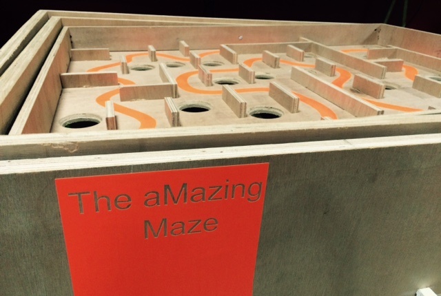
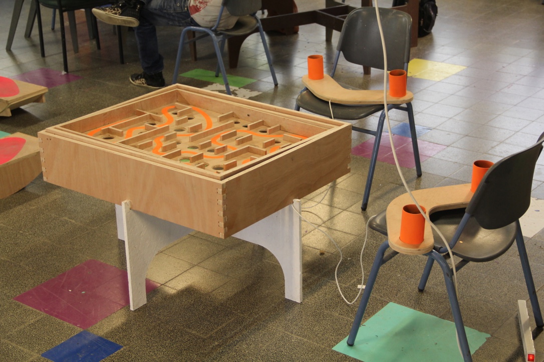
The body is made of a wooden plate with walls and holes, and two outer frames that enables free motion around two axis. Each axis is motored by a stepper motor. The control of each motor is by a couple of Photoresistors, embedded in a comfortable and intuitive wooden controller. Both input and output devices are connected to one micro-controller.
Wooden Structures
| Material | Size | Price USD |
|---|---|---|
| 20mm Plywood plate | 1200mm X 1200mm | 50 |
| 10.6mm Plywood plate | 1200mm X 1000mm | 15 |
| 5mm Plywood plate | 500mm X 500mm | 5 |
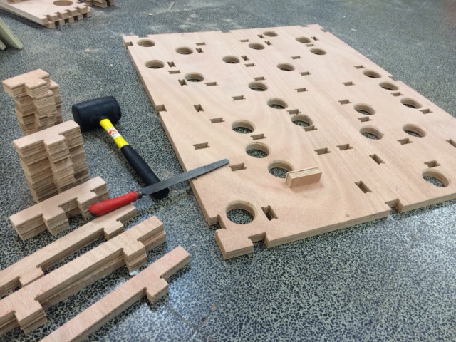
This is the main 2D filefor all of the milling. For each step I will include the specific file and the LOG files for the ShopBot, along with assembly instructions.
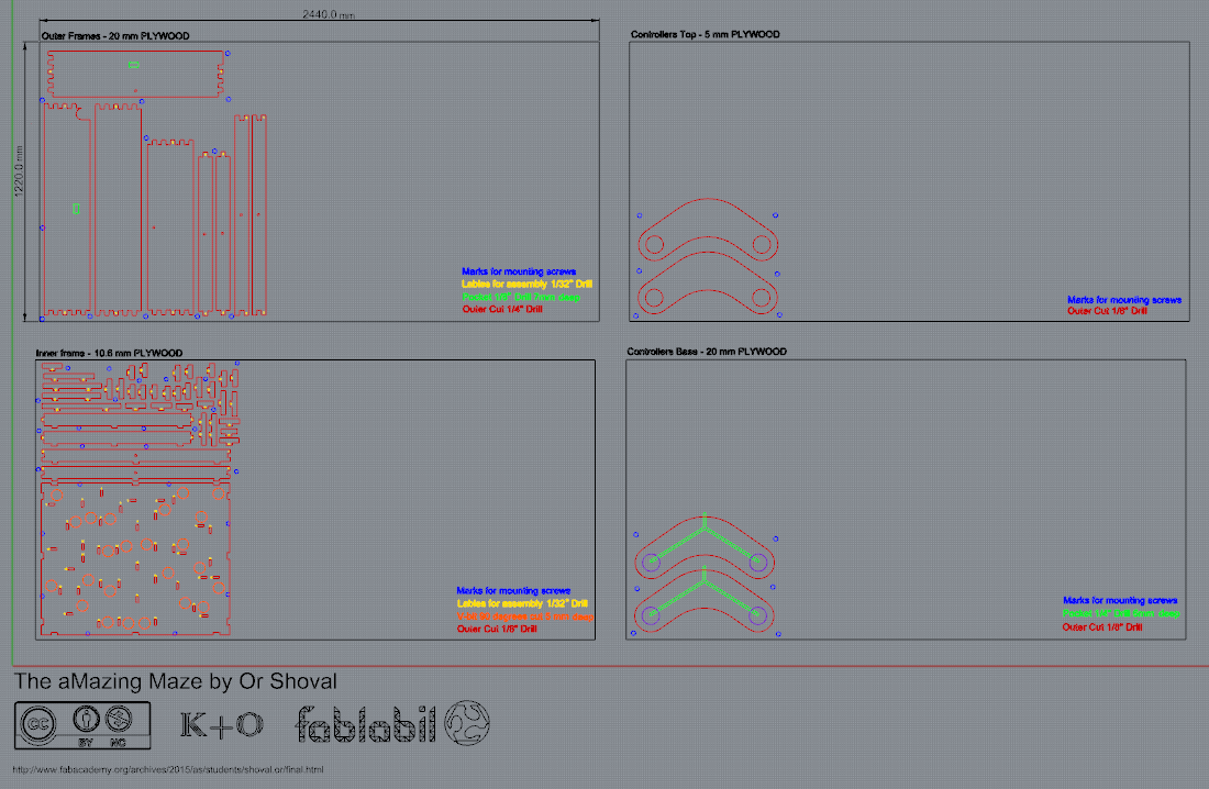
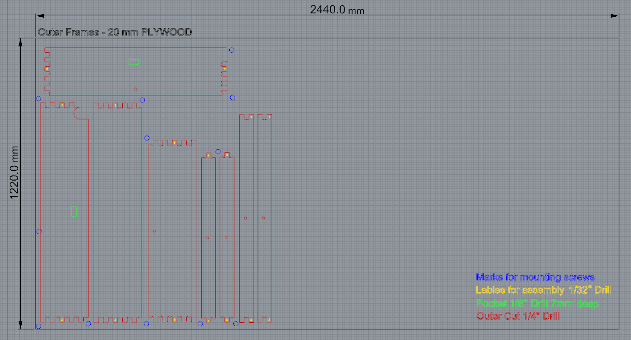
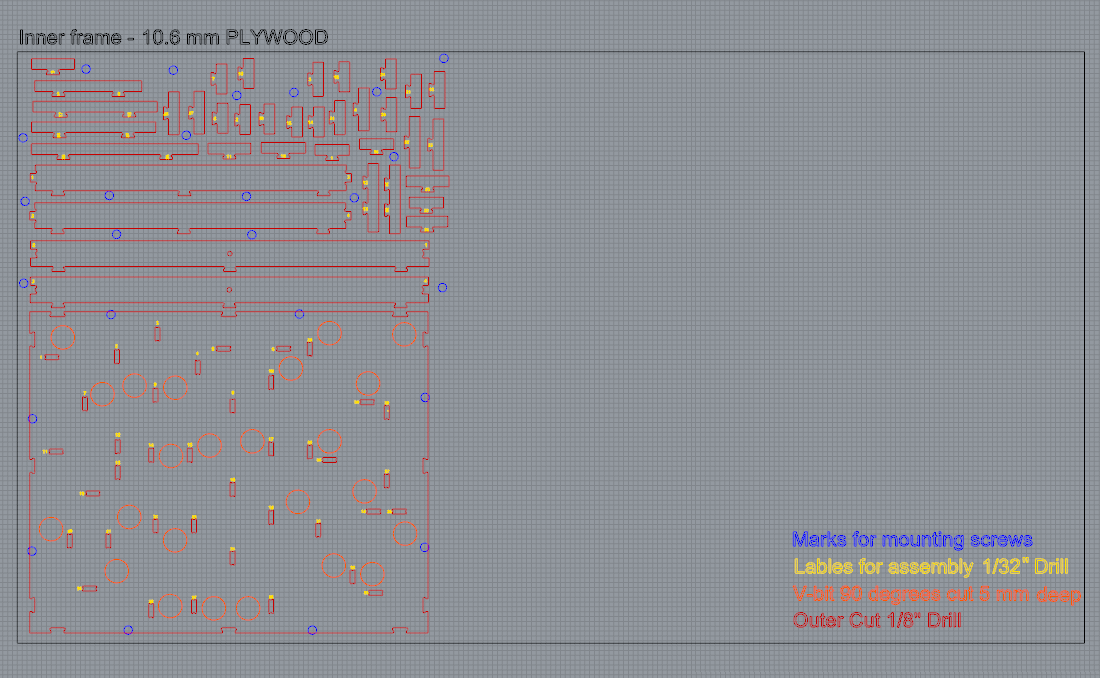
The Inner Plate is made of 10.6mm plywood. It has the most parts, its milling process consists of the most milling stages and it is the longest. The Outer Frames are made of 20mm plywood.
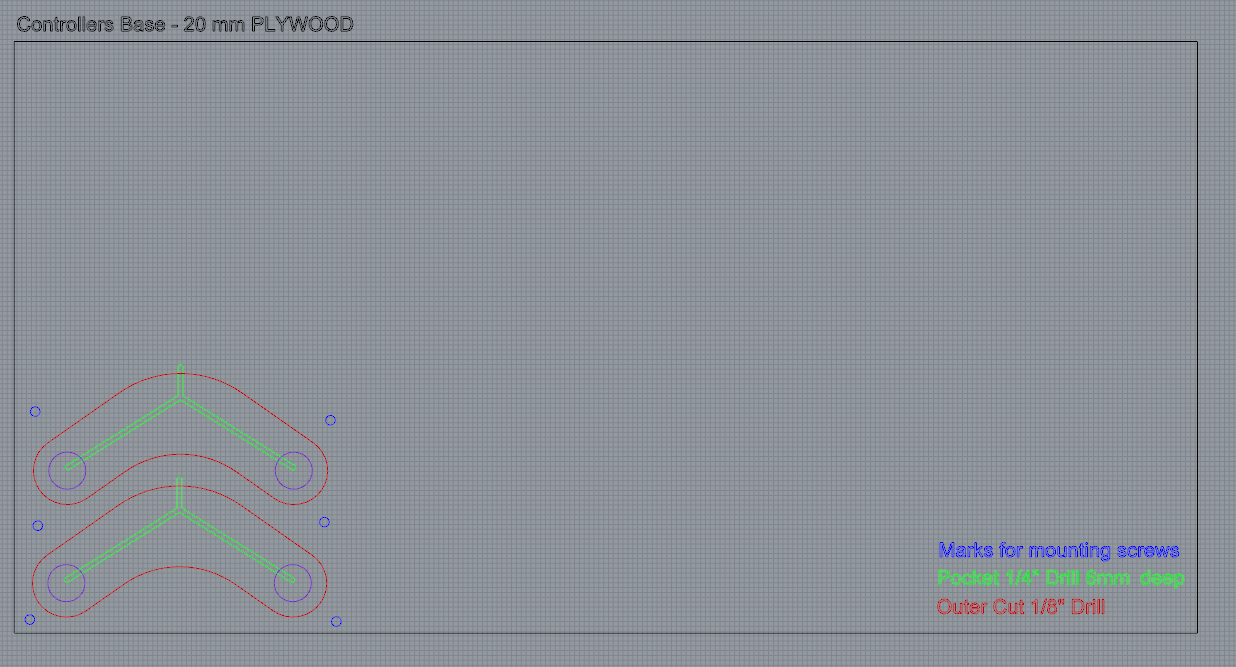
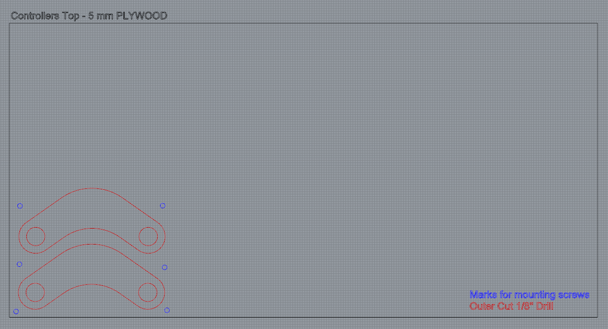
The Controllers are made of two plywood layers. A Base from 20 mm plywood that I milled with pockets for the cables and sensors and a Top 5 mm plywood to cover them and give the controller a nice finish.
For assembly process see Week 8
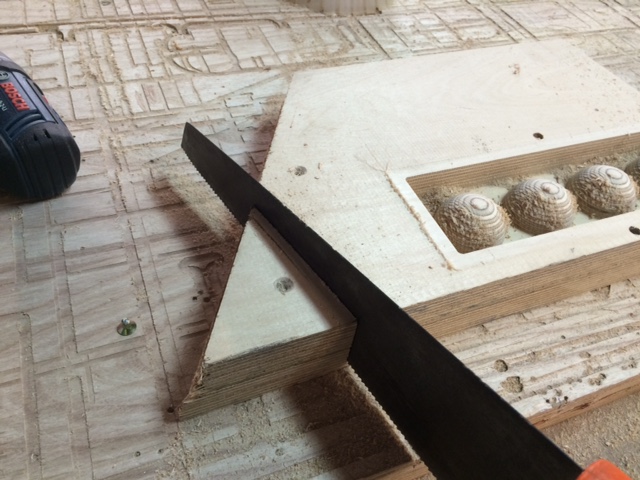
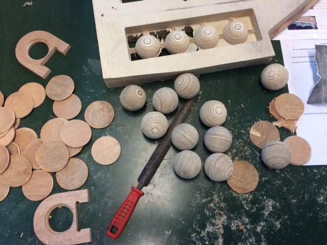
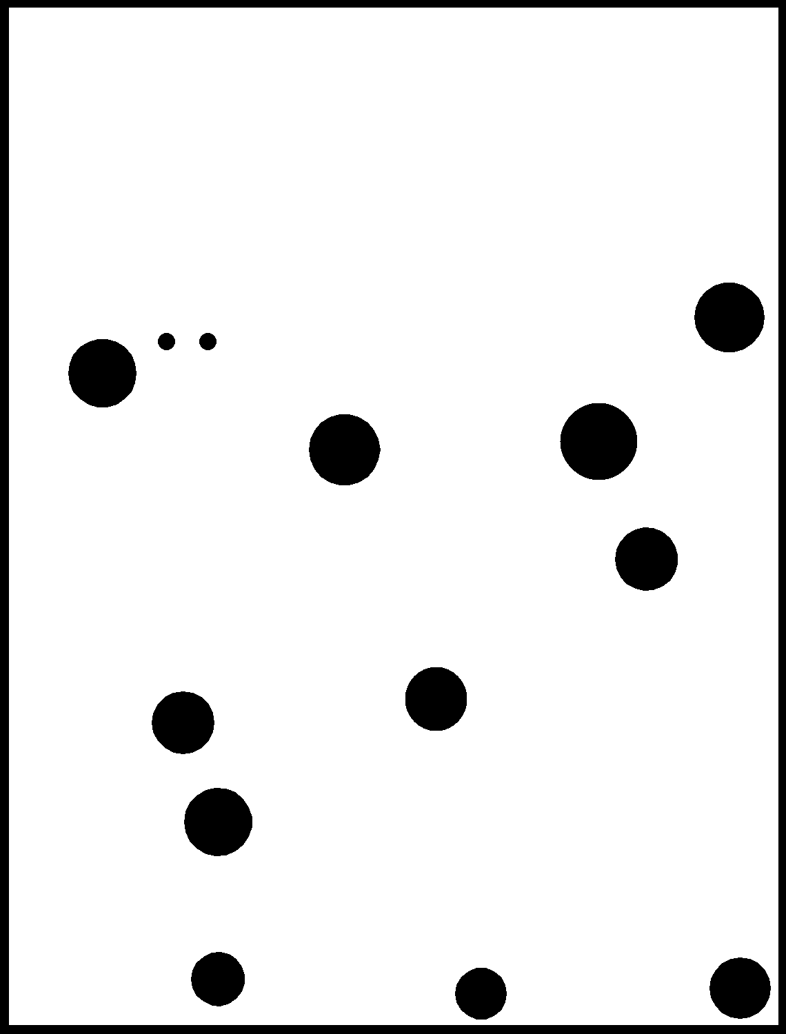
The ball is fabricated from a 46mm plywood (can be made from a couple of plates glued together). These are the 3D file 2D2D and Rhino files
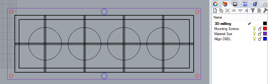
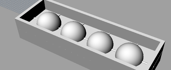
In order to get a perfect ball you need to place the material in a way that it can be flipped easily. First drill the two holes for the dowels in the wood, then drill the table in the same place, flip the wood and mount it using two dowels and drill two more holes in the wood again in the same place.
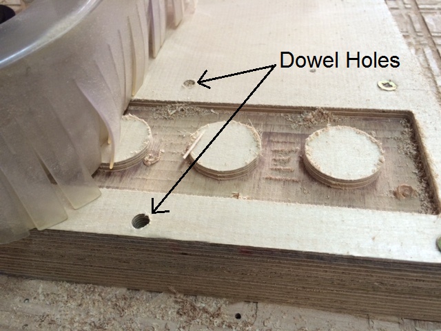
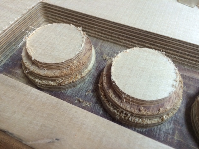
Run the rough and finish proposes, flip again using the dowels to mount the wood in the exact place and run the rough and finish proposes again
Electronics
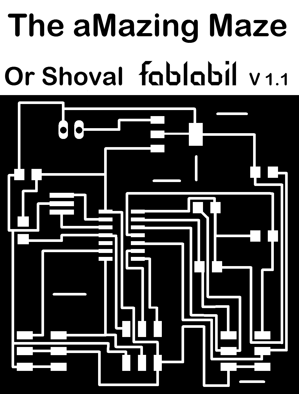
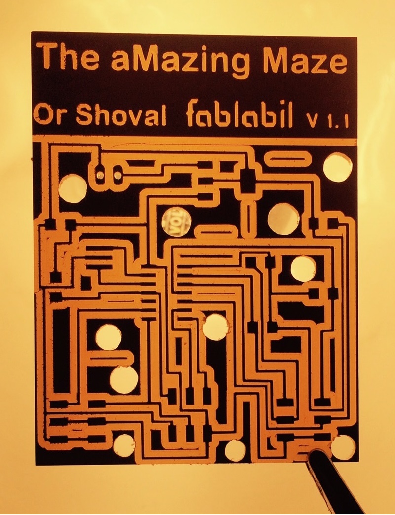
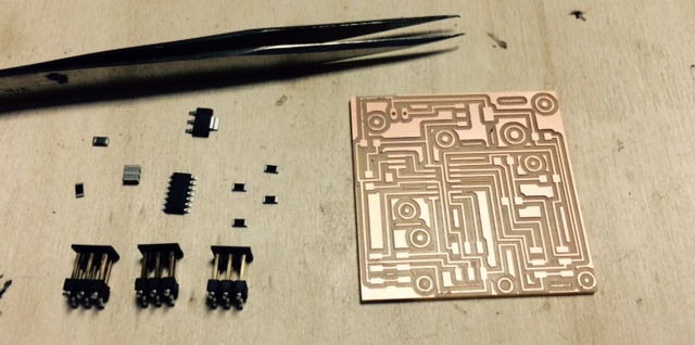
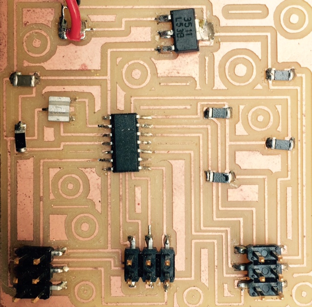
The Board I made is based on the AtTiny44 micro-controller. It has a 5V regulator and pin headers for the servos and controllers. You can download the Traces and Interior files
| Component | Picture | Quantity | Price USD |
|---|---|---|---|
| Regulator LM2940IMP-5.0/NOPBCT-ND IC REG LDO 5V 1A SOT223 | 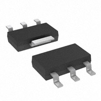 |
1 | 2.16 |
| atTiny44 ATTONY44A-SSU-ND IC MCU 8BIT 4KB FLASH 14SDIC | 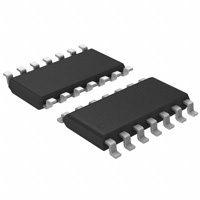 |
1 | 1.59 |
| 20MHZ Resonator XC1109CT-ND CER RESONATOR 20.00MHZ SMD | 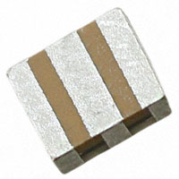 |
1 | 0.71 |
| 22uF Capacitor 1276-2728-1-ND CAP CER 22uF 16V 20% X5R 1206 | 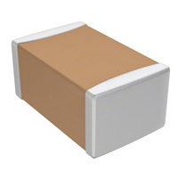 |
1 | 0.35 |
| 10K Resistors 311-10.0KFRCT-ND RES 10.0K OHM 1/4W 1% 1206 SMD | 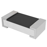 |
5 | 0.50 |
| 6 pin Headers 609-3487-1-ND BERGSTIK HDR 6POS .100" DR SMT | 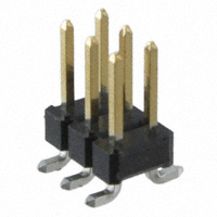 |
3 | 3.15 |
| 9V Connector BS3I-HD-ND SNAPS 9V 3" LEADS I-STYLE HD | 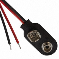 |
1 | 0.62 |
| Photoresistor PDV-P8103-ND PHOTOCELL 16-33KOHM | 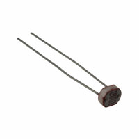 |
4 | 3.56 |
| Servo Motor HS-755HB Giant Scale Servo Motor | 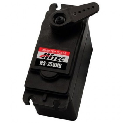 |
2 | 52 |
| 3 wire cable MULTI-PAIR 3COND 22AWG 100' | 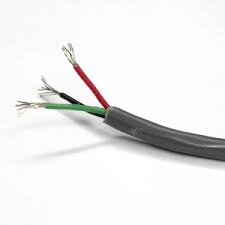 |
4 meters | 2.4 |
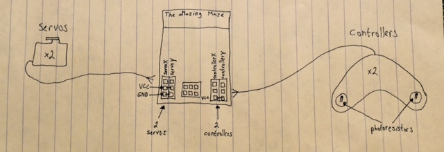
Inputs and outputs
Each controller has two photoresistors. Both share a common VCC
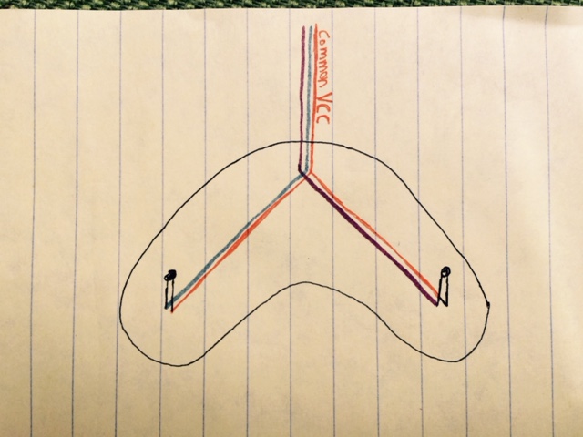
This is the schematics of all component connections.
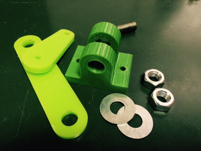
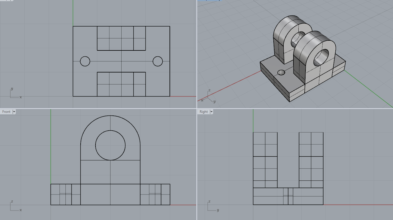
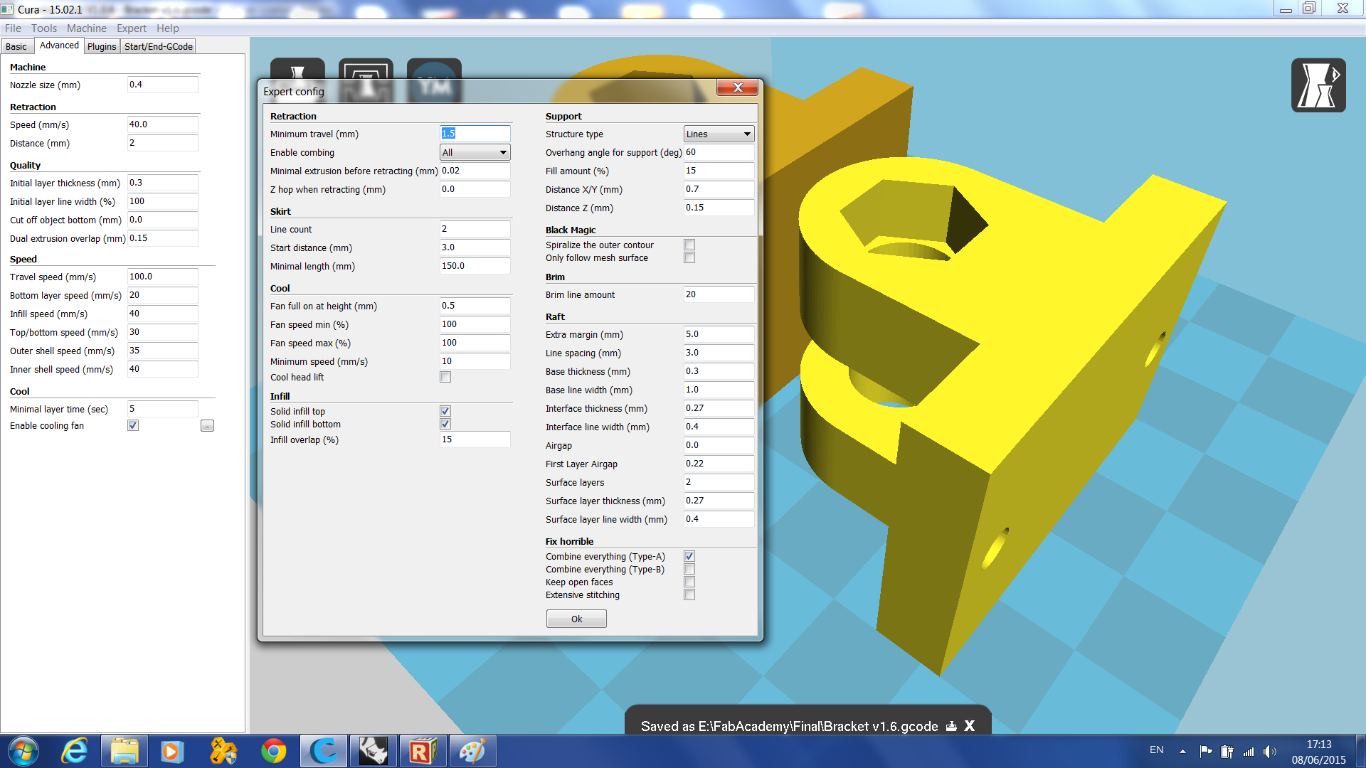
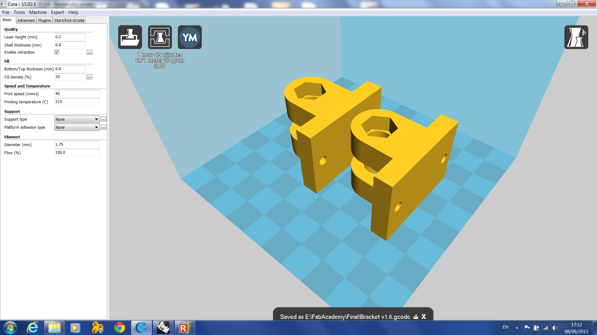
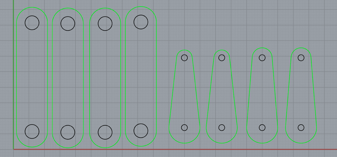
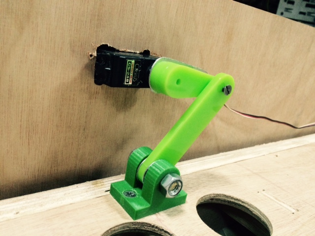
Mechanism
Each of the two mechanisms consists of a 3D printed brackets, laser cut plastic arms, 22mm threaded Rod, 2 bolts and 2 washers.
| Component | Quantity | Price USD |
|---|---|---|
| 3D Printed bracket | 2 | 10 |
| Laser cuted Plastic arms | 4 | 2 |
| 8X22mm threaded rod | 2 | 12 |
| M8 Hex bolt | 2 | 0.5 |
| A2 M8 washer | 2 | 0.2 |
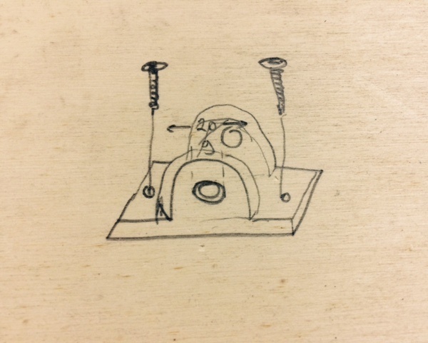
Assembly should be done when placing the game up side down. The servo motor has a pocket on the inner side of the outer frame, and the bracket should be attached to the inner 10.6mm plate of the game.
before attaching the plastic arms to the servo make sure that the servo is at its 90 degrees position (because the game plate is horizontal).
Programming
The code for the game is a simple one. It reads the analog data from the sensors, calculates the difference between each pair and translates it to angle for the servos. For using the AtTiny with Servo motors see Week 7
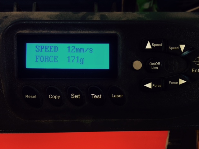
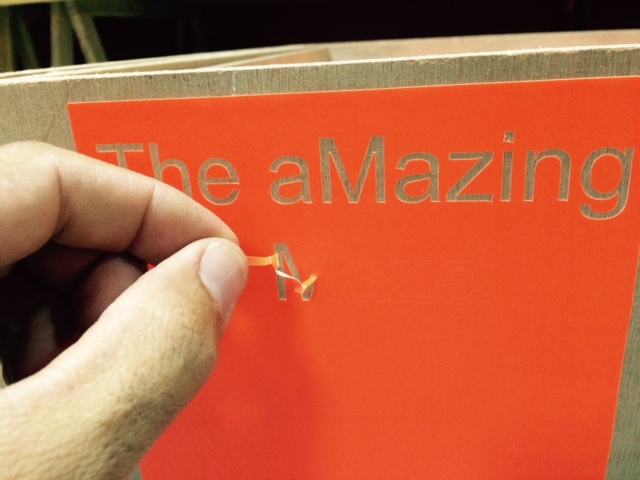
For the logo of the game I used the Vinyl cutter.
- © Or Shoval. All rights reserved.
- Design: HTML5 UP