10/6/2015 // Project Development //
Design
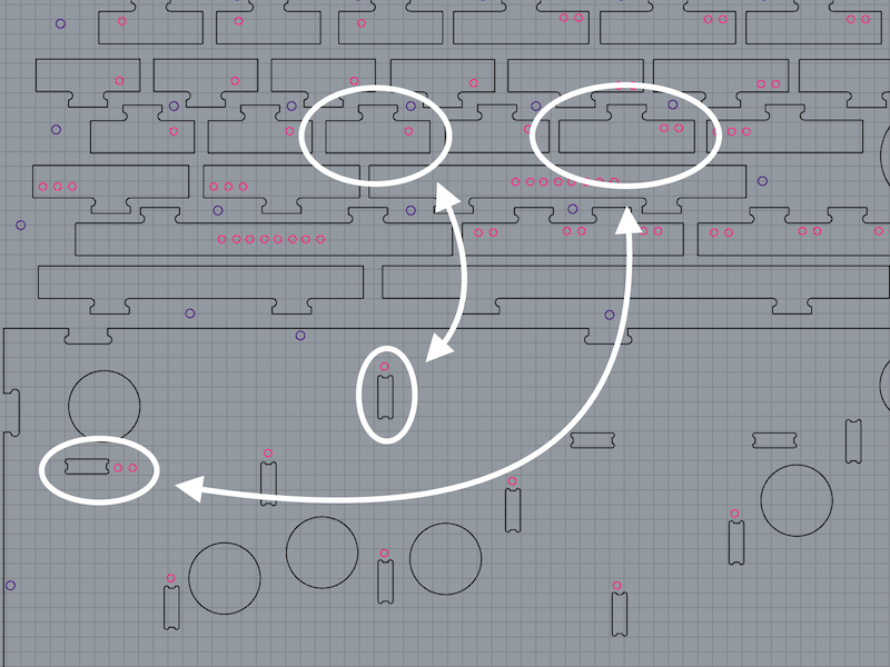
Me and Or Shoval decided to make this into a joint project but I made my own plan for the game board. I wanted to stick to the original plan as much as possible and I wanted to make it simple to manufacture. For the planning I looked at the original game and on Or's layout. I noticed that in both the original format and Ors' design there were many different sizes for partitions. I assume that the original game was made by hand so the maker didn't have any trouble cutting the small partitions by had, thus making them unequal in length.
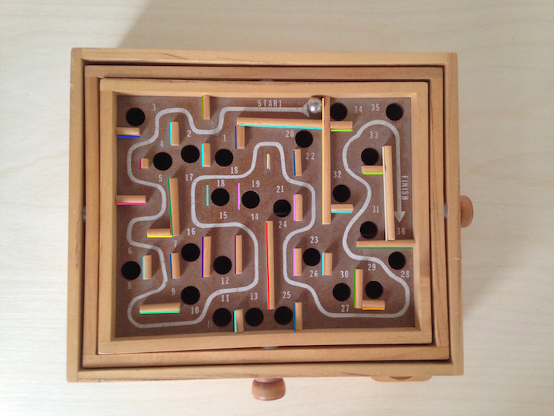
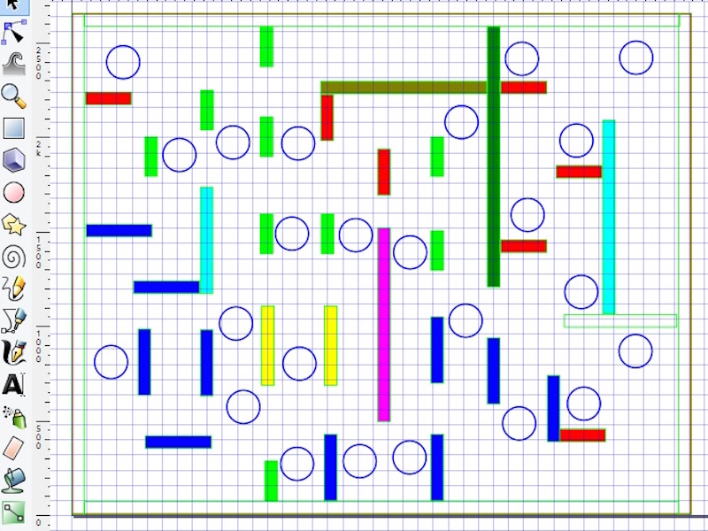
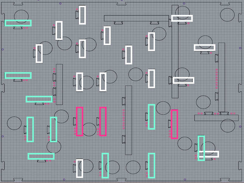
I wanted the assembly to be as simple and as fast as possible for everyone so I went back to the original board and placed stickers to mark each length. I gave special attention to the width of the path so that a ball can move freely on it. After some consideration I simplified the design so that there are only three standard sizes for the partitions and a few special sizes that stood out anyway.
When I was with the board design I went ahead with the design of the frames and spacers. I wanted to make a quick 3D model so I used SolidWorks, a program I LOVE to use. I haven't used it during this course because my computer killed itself so I was left computer-less for a while until I got my wonderful Mac. Unfortunately, SolidWorks doesn't work on mac (pun intended) so the only chance I got for playing with it was when a friend lent me his computer. Also, I like working with Rhino because I don't know it as well. Here's a small animation of the plan I made with SolidWorks.
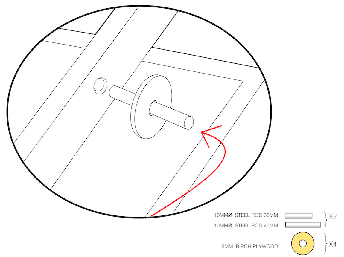
To make the axis of the game I used a metal rod and a thin plywood disk I laser cut. At first there were 3D printed but metal works much better, is cheaper and easier to make.
Making
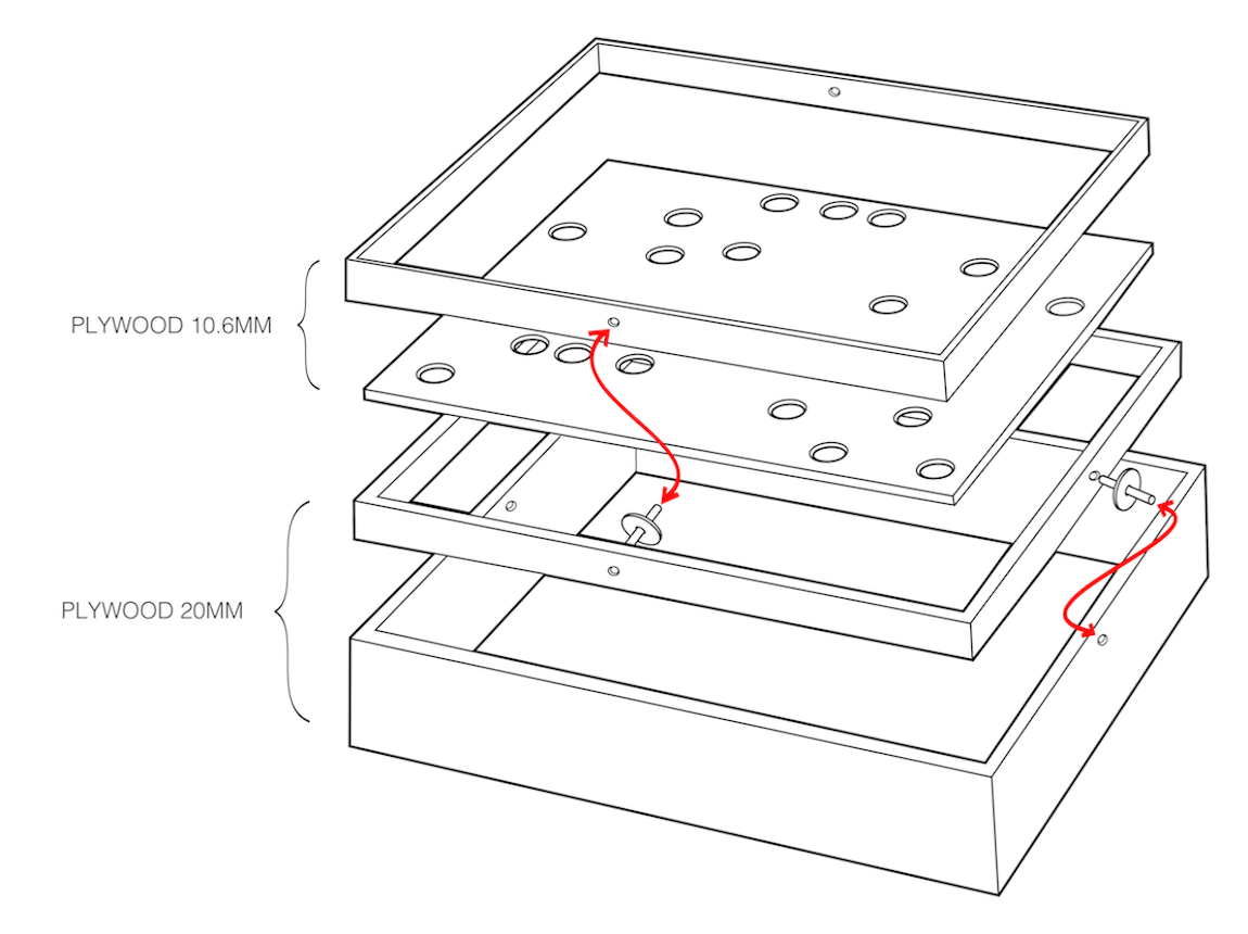
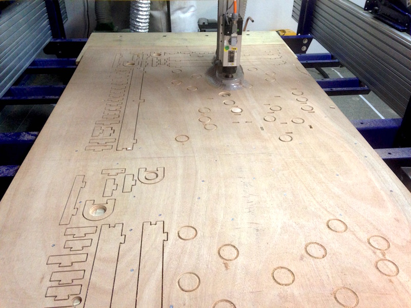
Once I had all the 2D plans I was free to start milling the plywood and to make the big parts of the game.
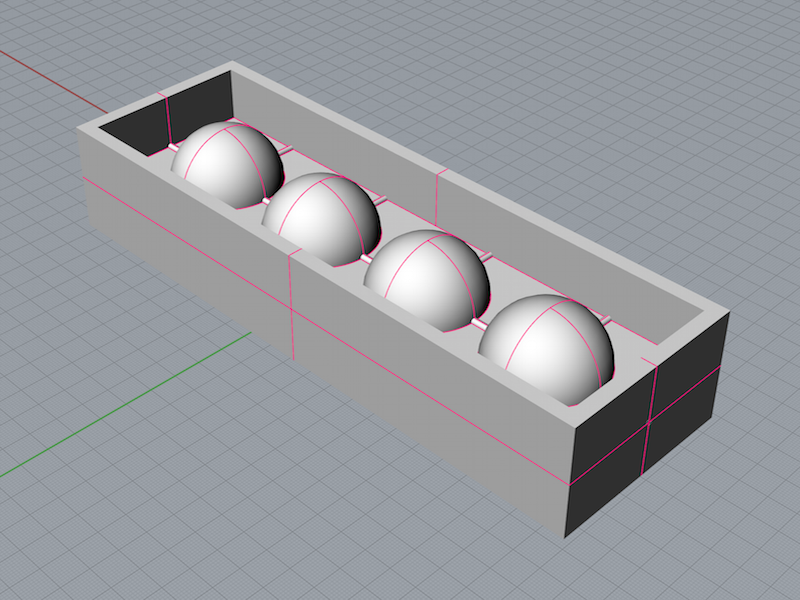
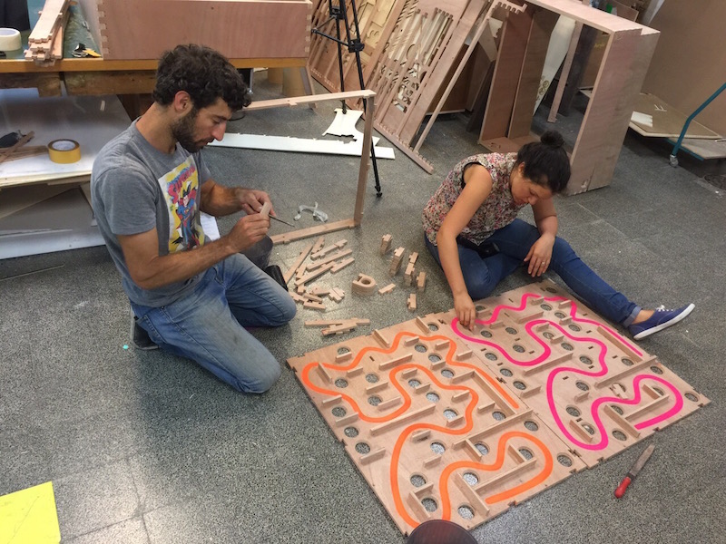
The final milling parts were the balls for the game. At first I looked for different types of materials for the balls of the maze. I thought about casting a clear polymer so that they'll be transparent and heavy but then I thought they might be fragile and will loose their clearness with time ,that would also be an expensive and time consuming process so I decided to keep looking.
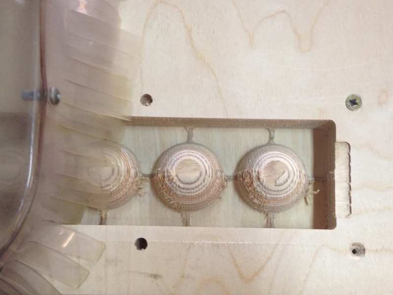
I knew They must be solid so that they can absorb hits they get from the floor if and when they hit it. In addition to that there was also the game itself to consider; if the balls aren't heavy enough then the ball won't roll when the board is tilted. Finally we choose plywood milling to make the balls. All though the process takes some time and effort I believe it is worth it because the result is both esthetically pleasing and sturdy. The only treatment needed is some rough and smooth sanding.
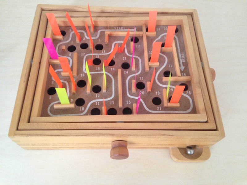
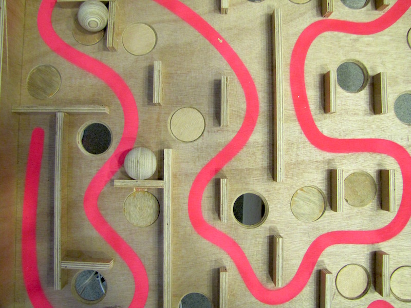
After I had all the parts needed for making The Maze I laser cut the path and painted it with spray paint (this can also be achieved using a vinyl sticker you cut)
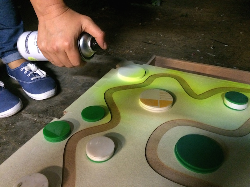
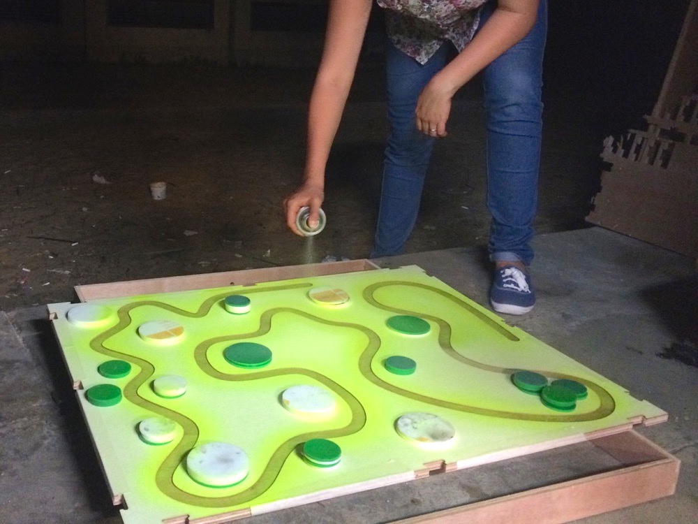
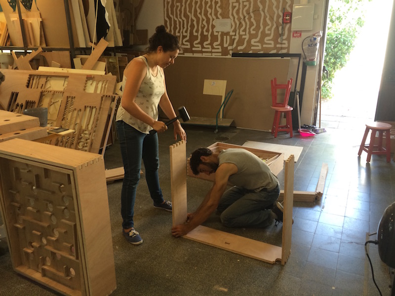
Once paint was applied we assembled the frames of the maze and the boards' partitions. The hole process was made without the use of adhesives of any kind. All we used was a rubber hammer to put the parts in place.
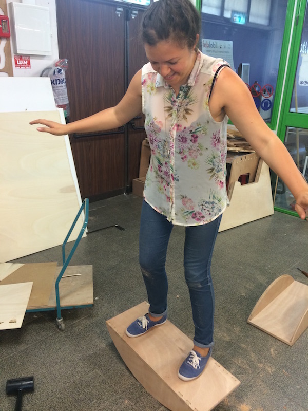
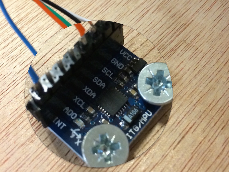
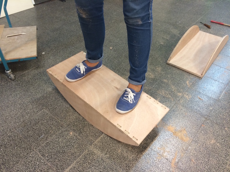
My next step was to assemble the foot controller.
The Gyro sensor was connected to the foot board from the inside, then the unit was closed with pressure and glue.
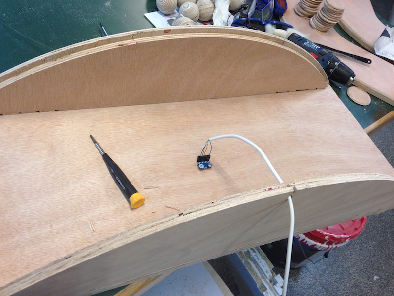
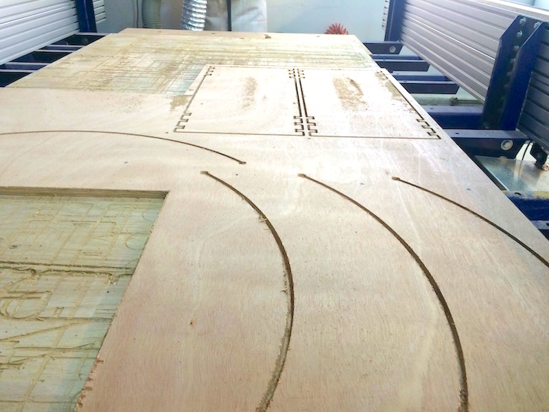
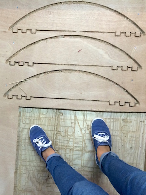
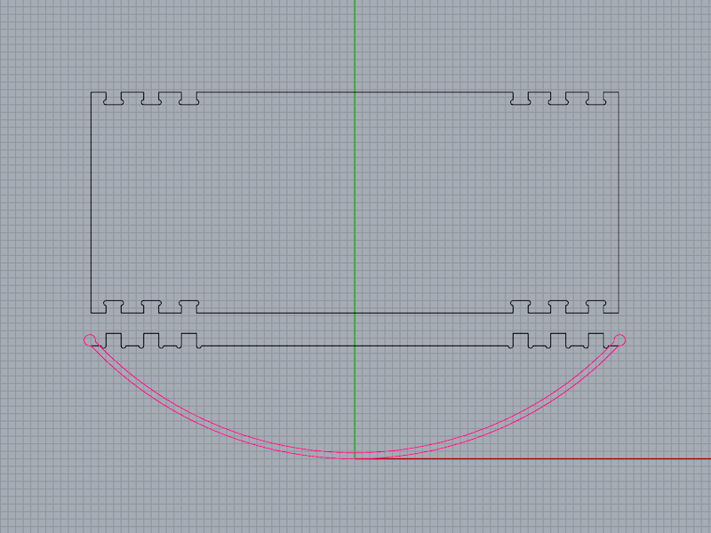
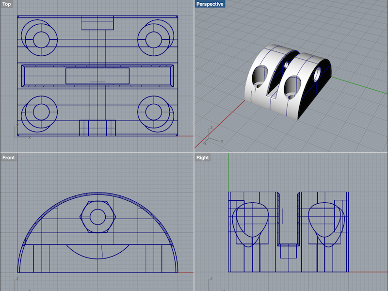
I designed it so it would be easy to assemble so the making and assembly are very straight forward. The red marking in the Rhino file are to indicate an engrave that creates a path for the bendy plywood.
The last step of design was the mechanism. In the first version we used thin aluminum sheet we CNC'ed to fit and thin rods we took from an old umbrella we found. Since this was just a temporary solution I needed to make something that someone else can repeat.
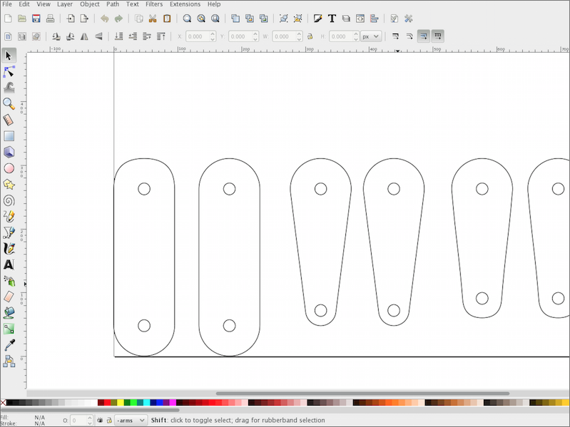
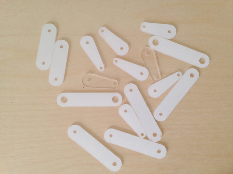
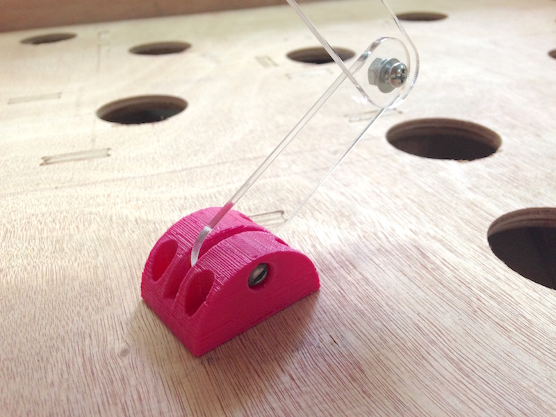
The mechanism is made of two plastic handles and a 3D printed part. The handles are connected the servo motor from one side and to the 3D printed part on the other. To make the handles I made a few tests to be sure that the movement range is right.
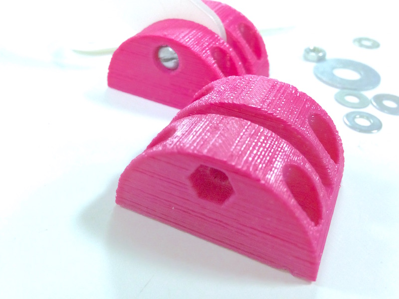
The second part of the mechanism is a 3D printed base that is connecting the game board to the handles.
Electronic Design
As an industrial designer I had lots of manufacturing processes and 3D design but very little experience with electronic design and programming so naturally I had more challenges in this part of the process.
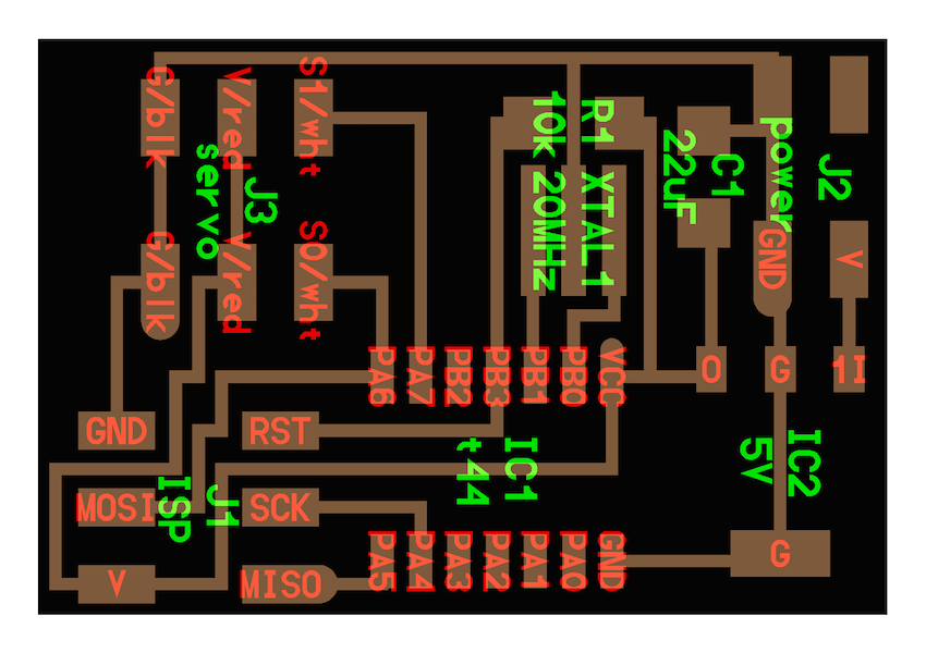
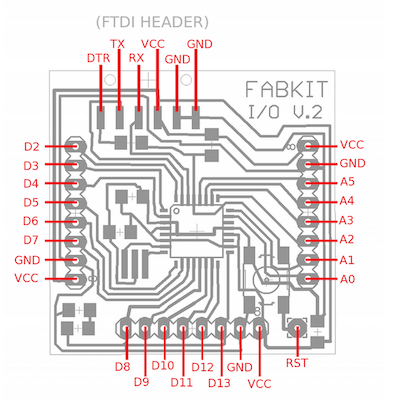
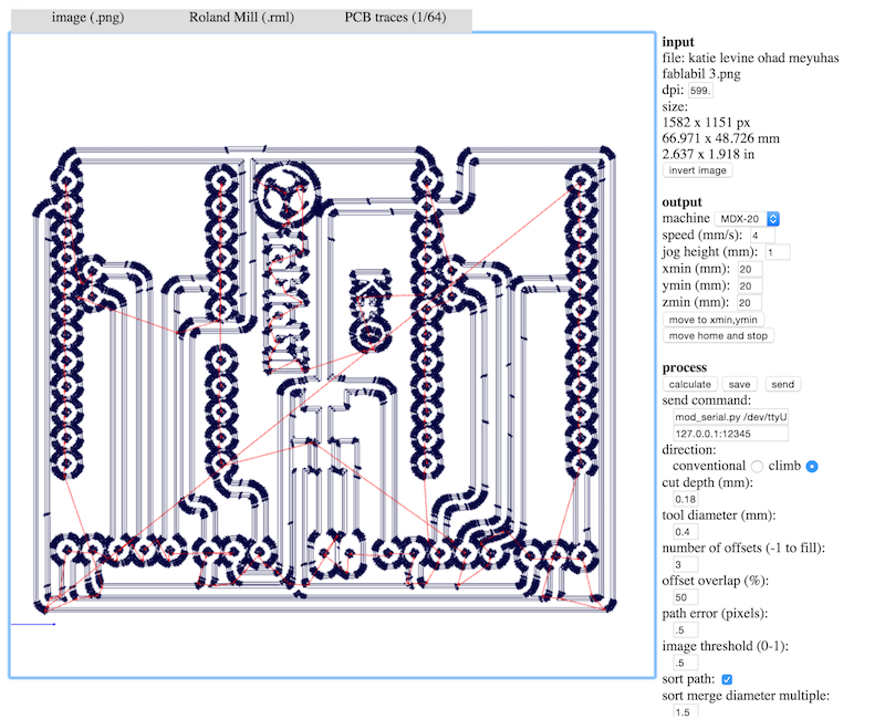
My first challenge was making a FabDuino.
I started with the files of fabkito2 from the Fab Academy site.
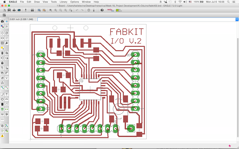
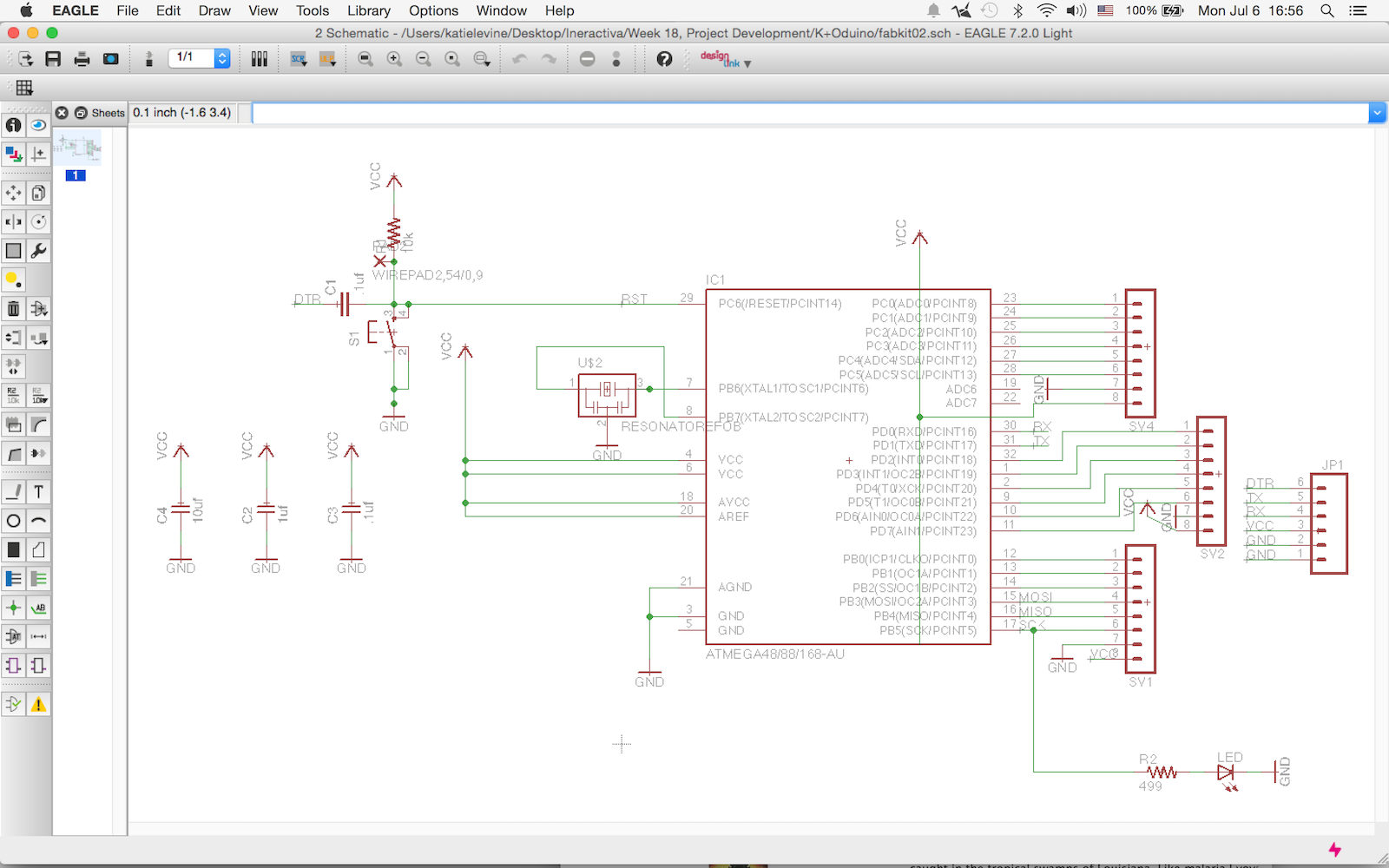
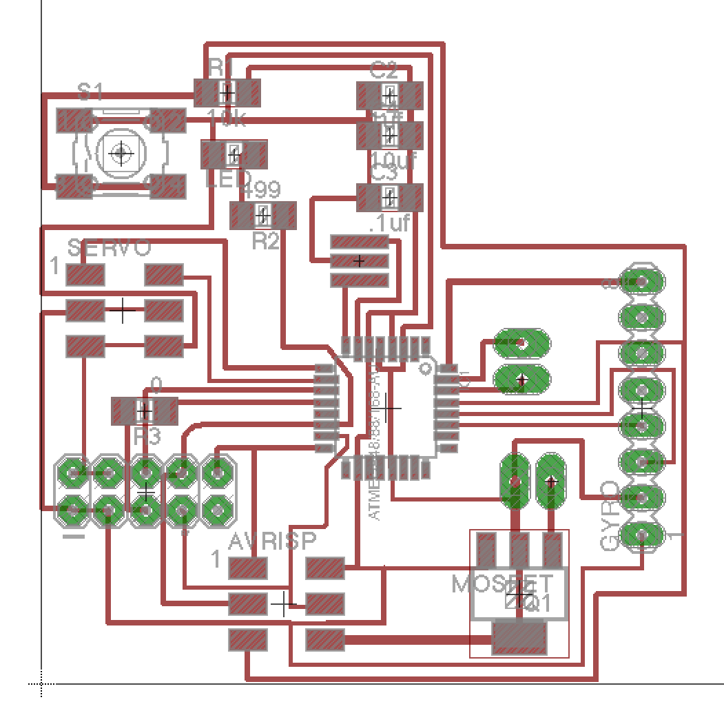
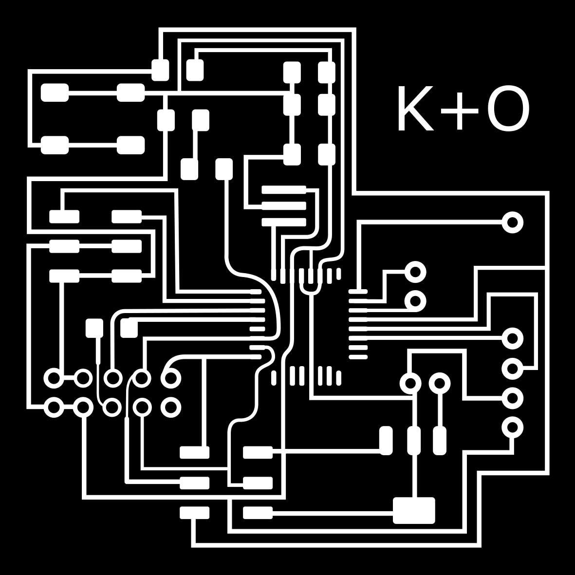
I wanted to make my -Duino board so that it would have specialized features to fit my product.
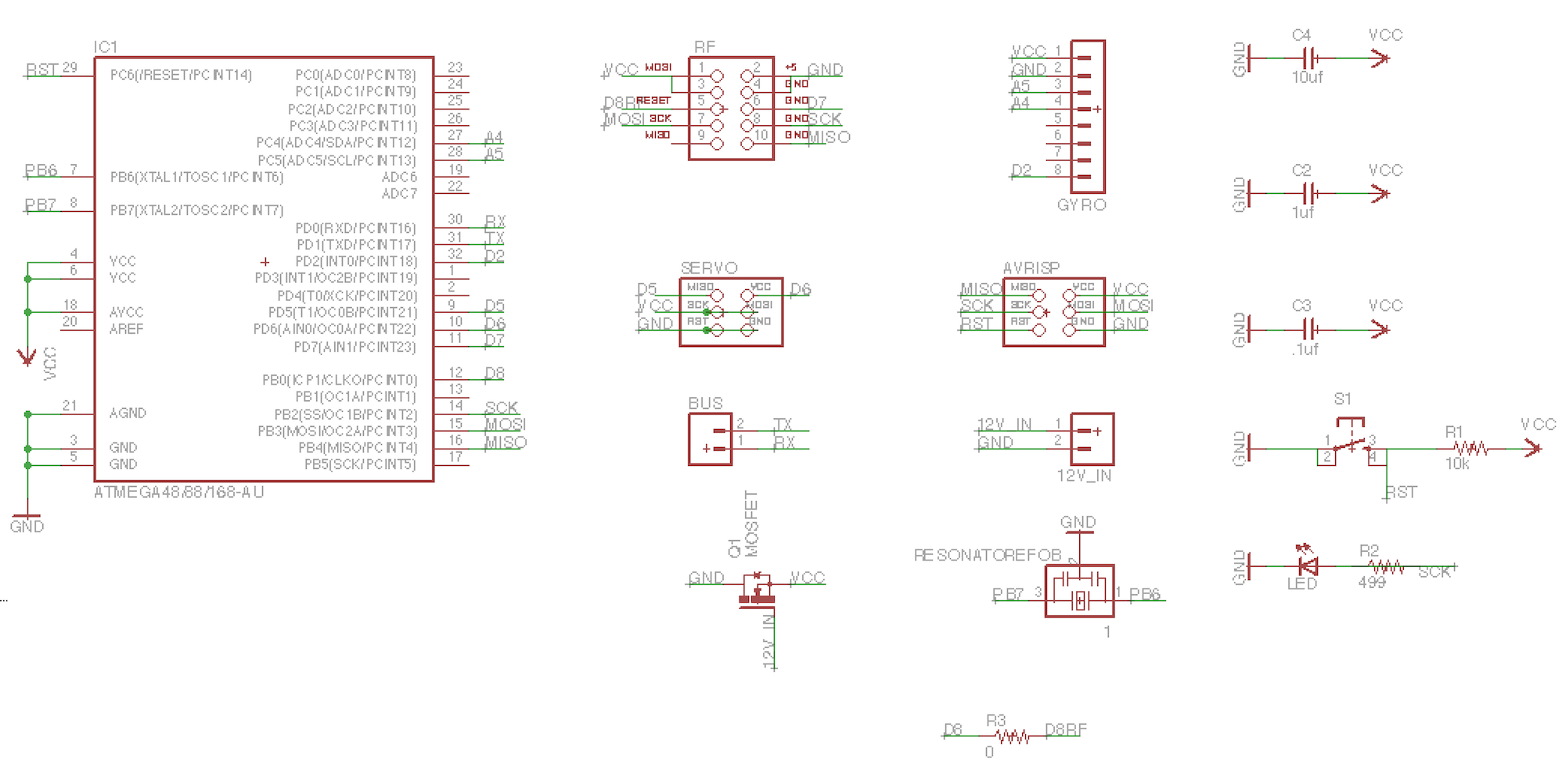
To do so I added Servo Motor, NRF component and Gyro sensor. I used examples that I found online and put them all together on my board, using the fabkit schematics as my base and working from there.
When I made the first board it didn't work and it took me some time to see my mistake; somehow, the VCC got connected to the MOSI in the AVR connector. I don't know enough to understand how the Eagle allowed such a mistake but I'm guessing it has something to do with the fact that I'm using the free version and it had its limits.
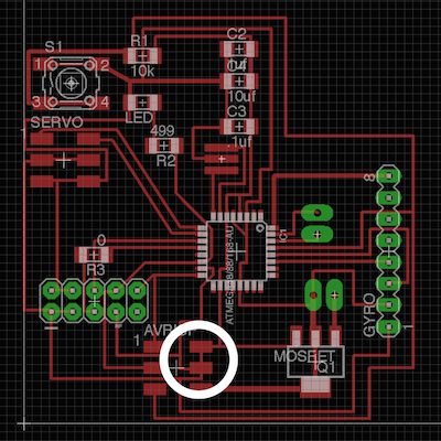
After I saw my mistake I went back to Eagle to fix it and to make sure there wern't any others. I did the best I could, hopeful it was my last change.
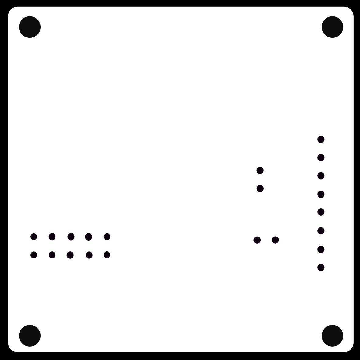
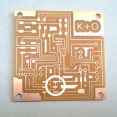
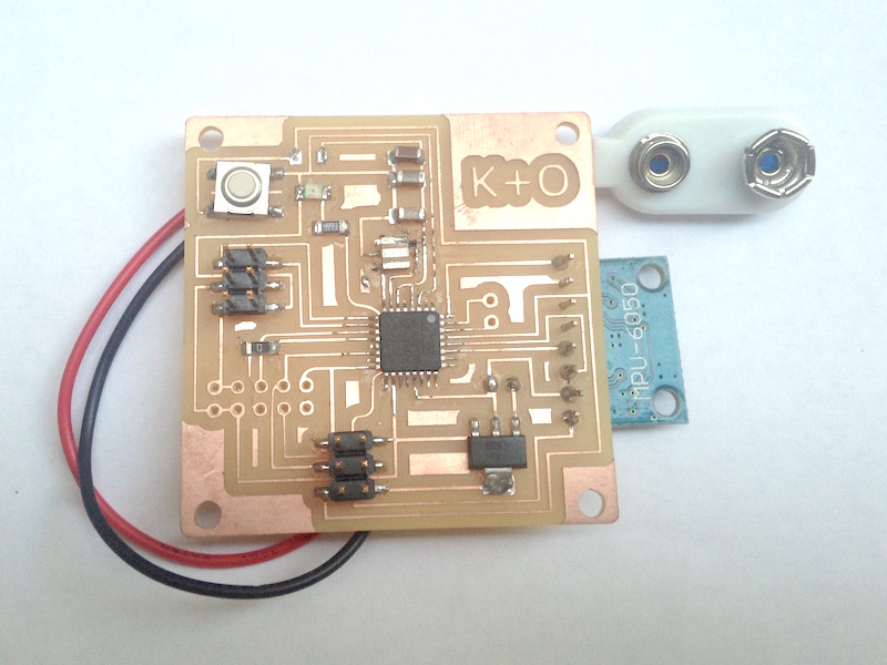
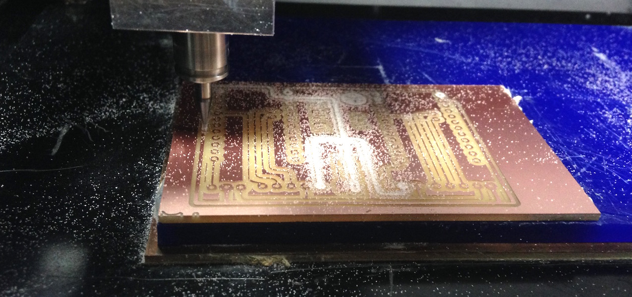
Finally I made the board, milled and soldered it successfully. I then went on to the next stage of programming. This is where I hit a block I wasn't able to overcome. I have tried many different ways, looked for answers wherever I could and asked my fab friends for help. Unfortunately it seemed I wasn't the only one facing the problem and non of the others had any different results. We suspect we got a bad batch of processors. Since we live in Israel and the post office here operates like it's still in the 1970' we did not have enough time to get new processors. I already made an order which I hope to get in the next few months. (Seriously, it takes 1-3 months for the ship to get here and then it gets to wait for the worlds slowest postal service treatment)
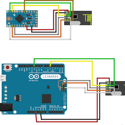
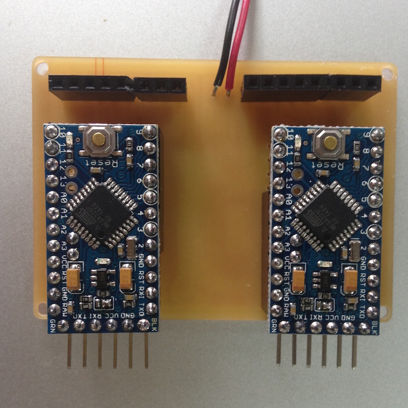
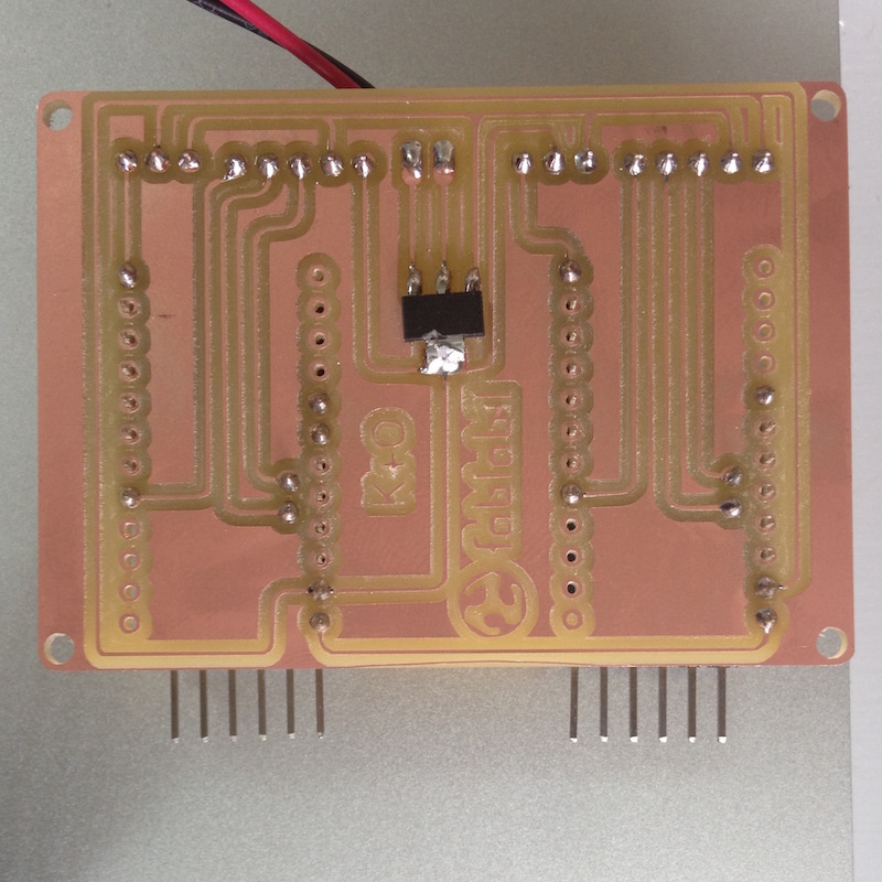
Since I had little time I decided to use two Arduino mini controllers so I made a shield for them with a MOSFET in between them.
The final stage of the project was the code. I wrote it using Arduino. I wish I had the time to master Python or other languages for programming and I know I will be pursuing that knowledge in the near future. Arduino is the best way for novice like myself to actually accomplish a code that works.
What I like about it that it works just like this hole project; it's simple, direct and easy to adjust and to understand.
Testing
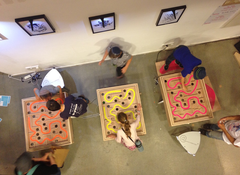
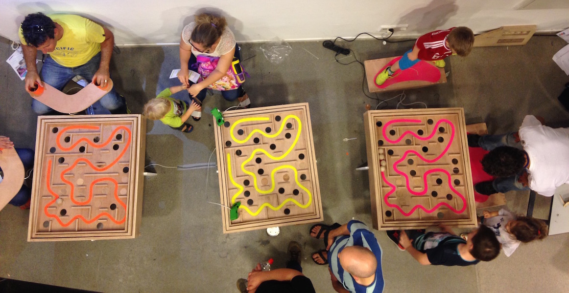
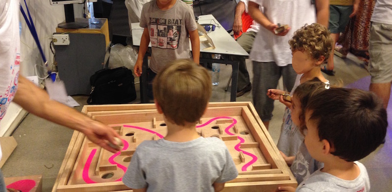
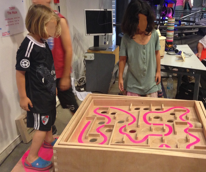
To test the project we decided to enter a Mini Maker Fair in Jerusalem. It's date was close enough to our final project presentation and it gave us the opportunity to check The Maze on a big amount of people.
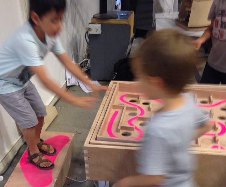
It was really amazing to see the way that people react to our project, to get feedback from children and adults and just to have fun with it.
During our time in the fair we discovered very quickly that we can adjust the difficulty level of the game by adding hole caps we made before; While the game without them is fun and challenging once we added the caps it was much easier to play and didn't take away the satisfaction.
Finally
To sum my projects here are a few points I thought about while making and testing it:
1. The plywood I used was cheap and simple and I would like to make this product with Birch plywood because it is stronger and looks better.
2. We need to add a bottom board that will lead the balls to a designated place.
3. The mechanism works great but the servo motors are too gentle, specifically when moved by hand. Many children tried to move the board manually resulting in the game crashing or the motors getting stuck.
4. The game is fun even without the motors.
5. As I've learned from a few physical therapy professionals this can be more than just a game; The Maze can be used for physical therapy for patients with an array of conditions.
6. The Maze is a great tool for children to interact, since it is played by two players it requires a great amount of verbal communication.
7. Teachers and Principals have requested to sit with us so we can introduce The Maze to their school.