
16 Mechanical Design Machine Design
Assignment
- To work on a group project to develop a machine that can automate a task
- To document the group project and individual contribution
MTM Group Project
Our group project using the gestalt modules is to build a foam cutter. This machine will take as input, a drawing and then proceed to cut the drawing from a piece of styrofoam.

Mechanical Design
The mechanical design was done by Roy, Edward and Walter.
I am practically hopeless in mechanical design, and we did not look at Nadya Peek's work on the construction. The mechanical team took one look at the examples and decided that they would build their own without any references. After looking at their work, I think it is definitely a piece of art which I would have taken forever to produce. They also designed and printed the mechanical parts for the collars, nichrome wire holders and stability sections for the MTM
Well done, boys!
Software design
We (Steven and myself) first looked at the example programs from the MTM repositories as well as the gestalt repositories and the code provbided by Nadya Peek (PyGestalt). In particular, we looked at the example for the xy-plotter in the examples/machines/htmaa section.
Steven started by experimenting with the code in the examples, we discovered that the important functions/modules that we required were:
- initInterfaces()
initialises the FTDI-485 interface, in which we had to insert our own reference to the FTDI-485 usb interface we used (/dev/tty.usbserial-FTXW6Q4L) - initControllers()
which defined the controllers that we were using. In addition to the x-y plane, we had to include a u-v plane to handle the other side of the cutter. - initCoordinates()
in which were specified the coordinate system in "mm" units. To this we also inserted the measurements for the u-v axis - stages.move()
which sent the absolution move positioning to the node - stages.jog()
which moved the motors a predefined distance for positioning - stages.[x|y|u|v]AxisNode.spinStatusRequest()
which returned the status of the node after a move command has been sent to it - stages.xyuvNode.disableMotorsRequest()
which disabled the motors at the nodes to conserver energy.
We also discovered that the moves that the MTM made were in absolute
units, which were sent in a list to the method moves(). Hence, we could
use the broad framework to then create a 2D foam cutter:
BEGIN
    Create Machine with 4 Nodes (x,y,u.v)
    Initialise Nodes
    Manual position to (0,0,0,0)
    Read in .csv file
    for element in moves-List do
        move to element
    Disable motors
END
Using a heated wire between the vertical posts would cut the styrofoam when the plotting was complete. The only things to do were to decide where the cut would start and how to create the cut-path to be stored in the CSV file.
Image Creation
In order to create the cut-path, we looked at several ways of developing a workable solution, these included writing one using Tkinter or PyGame but found it tedious, as we are not Python-enabled. The next best solution is to use a vector-graphics system (InkScape) to draw the image and to try to obtain the cut-path from the generated file. Inkscape saves its files in .SVG (Scalable Vector Graphics) and has an XML format in text which can easily be parsed using python.
After several experiments, Rodney created a SVG template which could be used to 'draw' the image to be cut which would be parsed to obtain the cut-path coordinates. The SVG template should be used to create the image to be cut and should have only a single cut path. Objects are limited to Rectangle, Circle or Path. The template also provides a guide to how large the object is going to look like when cut. The cut-path should be transfered to layer 1 to be converted into csv using our program svg2csv.py. The output file, will have the samefilename as the .svg file but using the extension .csv.
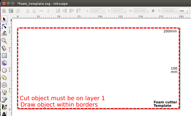
InkScape Template to use for drawing
As an example, the letter 'a' is drawn as text and the path traced out and placed on Layer 1. Changes to the path are made to allow for the cut for the internal body within the letter 'a'. There is no need to place the path at the top or bottom left corner as the program will take into account the cutting paths. As a check, we can see the XML code on the right showing the path on layer1.

The SVG definition for the cut-path starts with the attribute 'd' and points a list of coordinates. A breakdown of this data is
- 'd=' indicates a path of coordinates, starting with
- m x,y which indicates the absolute coordinates of the first point
- x,y ... and the relative coordinates of the next points relative to the first point
- z is the terminating character.
The svg2csv.py program locates and reads in this string, extracts the necessary absolute and relative points and coverts them into absolute coordinates. It then identifies the leftmost point and uses that as the start cut point. The rest of the points are rearranged without changing their sequenece to form the cut. We will assume that cutting wire is positioned to (0,0) hence the first cut will be to the leftmost point, which will also be the last point of the closed figure. These are then transformed and saved as a csv file for cutting
An overview of the svg2csv.py program is:
BEGIN
    Search for the element tag "p" at layer1, discard all other information
    Identify either 'rect', 'circle' or path 'p'
    Extract absolute point and all relative points
    Convert path to absolute coordinates
    Determine leftmost point (start), sort rest of the points accordingly
    Add exit point to (0,0)
    Save as CSV file
END
SVG to CSV path converter (Python)
Video showing part of the foam cutting process
Result of the foam cut
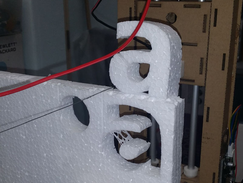
Foam cut letter A
- Cardboard construction drawings
- MTM Foam Cutter program
- Inkscape Foam Cutter Template
- SVG to CSV conversion program
- Sample letter A drawing
- Sample letter A csv output
Additional adventures into Foam cutting
Steven and I were not too satisfied with the result and decided to spend a day looking into the SVG code. We found that the SVG code has additional parameters which included an option 'c' which defined bezier curves which were difficult to code. One solution is to ignore the curve and treat it as a straight line. However we did not find out this solution until the project was over.
Reference:
- SVG code and the Paths definition.
- Replaceing Bezier curves with Straight lines
Instead, we looked at how to draw closed path vector diagrams and manipulate the drawing path so that we have a single drawing path. We can then export this path to SVG. However, when we looked at the code again, we found the occurrence of 'c' which indicated that bezier curves are use. Hence, we decide to look at another text-based vector drawing code - HPGL.
HPGL is simple to parse as we are only interested in the PD command which places the pen down to draw. Hence we could easily convert the vector drawing into HPGL and from there convert to .CSV for cutting. Initial conversions show that if we do not make the vector drawing as a single path, there will be places where the pen moves to start drawing in a separate location.
Using Inkscape I converted the object into paths and edited the path manually to obtain a single cut path. In order to check whether the paths were correctly formed and whether the cut would be successful, I also wrote a Turtle Graphics program which would simulate the cut. From the simulation, we found that InkScape always put in an additional PU move from the origin to the starting location. To simplify the process, we edited the HPGL file and deleted the initial code. We then converted the HPGL into CSV and then sent the file to the foam cutter for execution.

Modifying the cut path

Ensuring a single cut path

Cut Simulation using Turtle Graphics
Not being of a artistic mind, I have shamelessly borrowed this template (simpleStyle_8) from html5webtemplates, in recognition of a simple, cool and functional webpage design.