
14 Interface and Application Programming
Assignment
- write an application that interfaces with an input &/or output device
Journey
I decided to use the Light detector for this section. It would be great if I could have a program that could monitor the light conditions for my room and display it on a graph, so let me set down the requirements of my project for this week:
- use the ATTiny44 serial output and ADC input
- use the ADC to read in the light conditions for my room
- use a python program to show the light conditions as a graph
Instead of making another board, I decided to use a Light Detecting Resistor (LDR) instead of the Phototransistor, as we have plenty of those around and it was easy to setup. I did not have the datasheet for the LDR, but it was easy to calibrate as I knew that the resistance varies with the intensity of light. By placing the LDR and a 100K variable resistor in series, I could adjust the voltages read in. I found that the best value to use was around 10K to 30K which gave a read of 50 (direct flashlight) to around 900 (dark room). I then removed the variable resistor and replaced it with a 10K resistor for better stability in the readings.
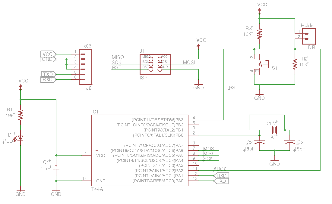
ATTiiny44 LDR schematic
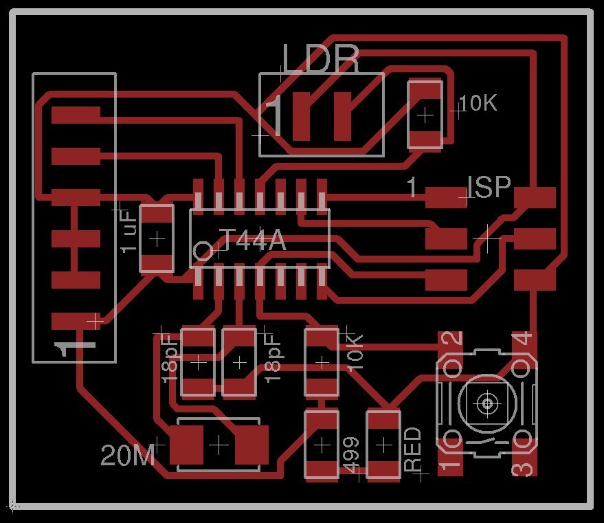
ATTiiny44 LDR board
Design files: 14_ATTiny44_LDR.sch, 14_ATTiny44_LDR.brd
The LDR output is connected to pin 11 (ADC2) of the ATTiny44 which will
be used to read the analog voltage. The analog voltage is converted to
a decimal value between 0 and 1024. Since we know that the voltage will
not drop below 0.25 volts (extremely bright) and 4 volts (extremely dark)
the counts would be between 50 and 800. The program is very simple to
write and requires only the use of the Serial library. Since the amount
of memory is not essential, I am using the Arduino IDE for this, by mapping
the necessary pins for SoftwareSerial and ADC lines.
const int LDR = A2;		// PA2/ADC2
const int TX = 0;		// PA0
const int RX = 1;		// PA1

SoftwareSerial mySerial(RX, TX);

void setup(){
	mySerial.begin(9600);
}


void loop(){
	// take readings every 1/2 second
	int ain = analogRead(LDR);
	mySerial.println(ain);
	delay(500);
}
I first verified the output using the serial terminal and checked that I was getting integers (one per line) from the ATTiny44. I could then begin to write a p\Python program to read and display the results. This can easily be done by using the PySerial library. However, I also wanted to display the results in a graph. Using a static graph, I could at best monitor about 1000 readings, however, if you had a scrolling graph, then the monitoring would be dynamic. I just had to have something like that.
With a little searching, I found a Python library - Matplotlib and went through the basic tutorial on how to plot the graph. Another site - Plotting real-time data with the Arduino showed how to use a queue data structure to queue and dequeue the data, letting Matplotlib to handle the plotting. With this I was able to now plot the light leveles in my room using a moving graph
The following graph shows the result of such a plot, with the dip in the plots showing the instances where a bright torch was shone directly on the LDR
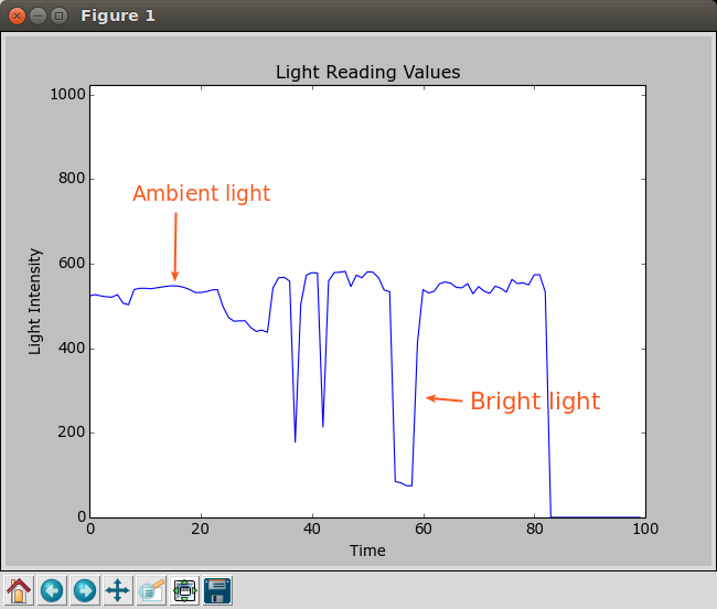
Light Intensity Graph
Programs used
- ATTiny code at44_ldr.ino
- Python code plotlight.py
Other things got done...
Ubuntu - How to fix the use of "sudo"
- Each time I used avrdude (or used the Arduino IDE) I had to fix the use of avrdude under Ubuntu Linux 14.04, so I decided to fix it once and for all. There are 3 ways of doing this, depending on whether your udev works, so I'll put it here for reference.
The methods are:- Fix udev, follow the write-up below, remember to unplug and plug your device after you have finished. You can also use the group plugdev, provided you are a member of the group:
# First use lsusb to determine the USB devices # Bus 003 Device 007: ID 16c0:05dc Van Ooijen Technische Informatica # Bus 003 Device 008: ID 1781:0c9f Multiple Vendors USBtiny # # Write up the usb rules as below, save the rules in /etc/udev/rules.d, # you might want to use the filename 81-usbISP.rules # You can change to group to dialout, plugdev or adm # # Reload or restart udev # sudo reload udev # or sudo /etc/init.d/udev restart # # Plug and un-plug the board to initialise # # USBtinyISP Programmer rules SUBSYSTEMS=="usb", ATTRS{idVendor}=="1781", ATTRS{idProduct}=="0c9f", GROUP="plugdev", MODE="0666" # USBasp Programmer rules http://www.fischl.de/usbasp/ SUBSYSTEMS=="usb", ATTRS{idVendor}=="16c0", ATTRS{idProduct}=="05dc", GROUP="plugdev", MODE="0666" - Change the ownership of the avrdude, here I have installed the avrdude from the avr-c toolchain. If you are using the Arduino toolchain, your avrdude will be in a different location, not on the path.
# manual installation -  /usr/bin
#
# installation from Arduino IDE - /opt/arduino-1.6.4/hardware/tools/avr/bin
#
sudo chmod +x /usr/bin/avrdude
- Fix udev, follow the write-up below, remember to unplug and plug your device after you have finished. You can also use the group plugdev, provided you are a member of the group:
Roland iModela Routing of PCBs
- We tried using the 0.4 and 0.8mm endmills but ended up breaking a few of them, so we have now resorted to the V-shaped engraving mills (0.1mm x 30deg and 0.1mm x 10 deg). So far we are using the 30deg V-bits with good success rates.
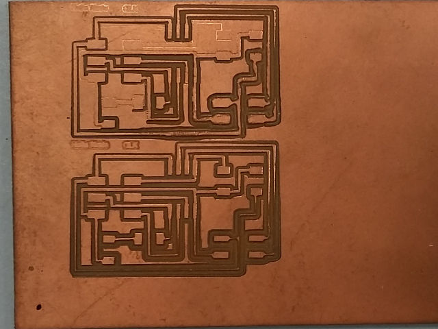
- Here are some results of the work we've been accumalating and the boards that are generated. We are quite pleased with the overall result.
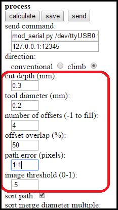
Process Parameters
Cut depth = 0.3mm
Tool diameter = 0.2mm (using a V-shaped bit)
Num of Offsets = 4
Offset Overlap % = 50
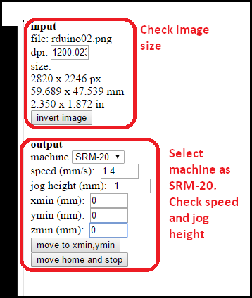
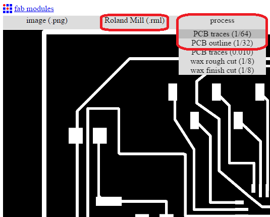
Check the isolations by viewing the output generated
Check the size of the board to be cut from the screen>brr> Select SRM-20 (which has the same parameters as iModela)
Speed = 1.4 mm/s
Jog Height = 1 mm
Save the file (.rml) for export to the Roland for cutting.
Bad results using 0.8mm end-mills. The bits keep breaking as the parameters are not tuned yet.
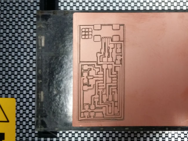
Poor adhesion with weak double-sided tape. You can see the shift in the milling.
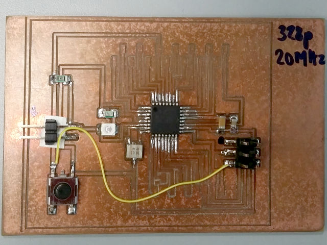
RDuino v1.0 with wrong 2mm headers
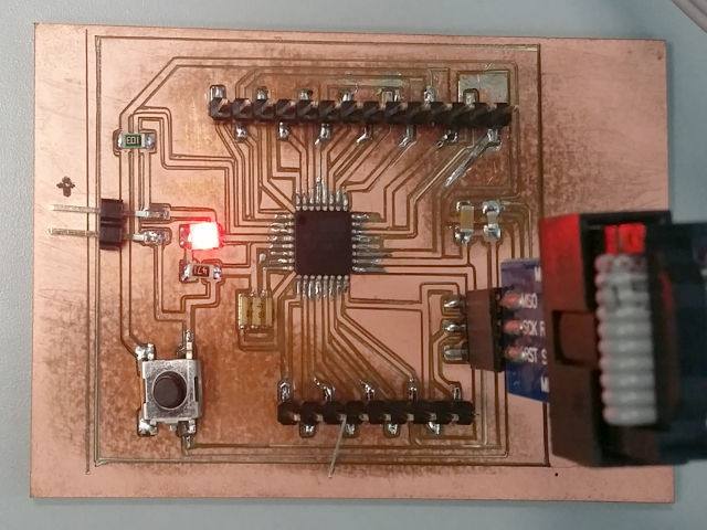
RDuino v2 using the ATMega328p and ISP header in production.
References
Not being of a artistic mind, I have shamelessly borrowed this template (simpleStyle_8) from html5webtemplates, in recognition of a simple, cool and functional webpage design.