
10 Input Devices
Assignment
- Measure something
- Add a sensor to a microcontroller board that you've designed and read it
Journey
Sensors with the ATTiny44- The ATTiny44A is a very small microcontroller which can be easily adapted to interfacing devices. It can be optimally operated with an external resonator or crystal circuit for exact timing operations or set to use the internal clock at 1 or 8 Mhz.
- The design of the circuit is very similar to the FabHello board and although it was relatively simple to design and build, we decided against creating new boards as the milling process was not producing result.
- Hence, like all good Electronics Engineers, we went back to the time-tested breadboard/veroboard/stripboard solution that we know and like so well
- Walter's board tested bad, so we sat down and re-designed a general purpose ATTiny44A board using the full 14-pin DIP and a stripboard. The design uses a 20MHz crystal circuit, with all pins extended to the edge of the board. We also provided an LED for indication of power, and a circuit to use one of the pins to test operationality using the standard Blink program. The design of the board took 1 hour with the help of Eagle and another hour to build on stripboard. We then used the board for all our interfacing purposes.
- Steven ordered some of these after discussion and going through the inventory list as we have not played with these devices yet. We found some references on the PIRs from LadyAda/Adafruit's site. It proves to be an interesting device.
- PIRs are pyroelectric sensors which can detect infrared radiation. Hence we use this to detect motion changes as everything (?living?) emits heat.
- I first tested the PIR using a LED and 220 Ohm resistor connected to the middle pin of the PIR. Vcc is connected to the leg nearest the diode, with the other leg connected to Gnd. When motion is detected, the led lights up.
- Using the information from LadyAda/Adafruit's site we discover that the PIR is set to detect motion. There are two potentiometers on the board which allow you to change the timing of the detection LED and the other determines how long the LED will stay unlit when there is no motion. As we are only testing the PIR, we decided not to change any of the settings.
- The connection to the ATTiny is simpler than usual as all we have to do is to connect the detect pin to an input and use the microcontroller to determine the state of the pin and determine when there is a change of state (LO->HI) motion is detected, (HI->LO) the motion has ended.
In addition, we will use one pin to detect the motion and display it on the LED. - The plan for the code is as follows:
Initialise input and output pins
LOOP
	curState = read input pin
	if (curState is HI)
		output a HI
		if (oldstate == LOW
			print "Motion detected"
		oldState = HI					// store the state
	else
		output a LO
		if (oldstate == HI)
			print "Motion ended"
		oldstate = LO
We now translate this into AVR-C using the Arduino IDE and mapping out the necessary pins. For my first attempt, I decided to use the FabHello board with the breakout pins to test the circuit. (Also, our PCB mill is not servicable and we have no access to the PCB process this week).
// Software to input data from the PIR

// pin definitions
const int inPin = 3;         // Ard=3, T44=PA3
const int outPin = 7;        // Ard=7  T44=PA7
const int RX = 0;            // Ard=1  T44=PA2
const int TX = 1;            // Ard=0  T44=PA1

ss = SoftwareSerial(RX, TX);

void setup() {
	// put your setup code here, to run once:
	pinMode(inPin, INPUT);
	pinMode(outPin, OUTPUT);
	ss.begin(9600);            // set to 9600
	digitalWrite(outPin,LOW);
}

int oldState = LOW;

void loop() {
	// put your main code here, to run repeatedly:


	int currState = digitalRead(inPin);
	if (currState == HIGH){
		digitalWrite(outPin, HIGH);
		if (oldState == LOW)
			Serial.print("Motion detected ... ");        // motion detected
		oldState = HIGH;
	}
	else {
		// digitalWrite(outPin, LOW);
		if (oldState == HIGH)
			Serial.println("Motion ended");
		oldState = LOW;
	}
}
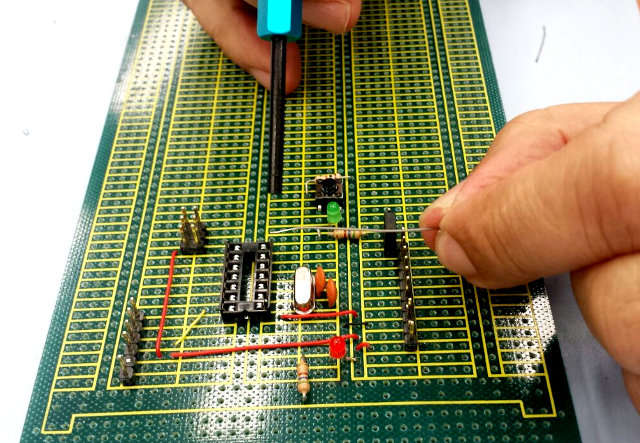
Wiring a stripboard
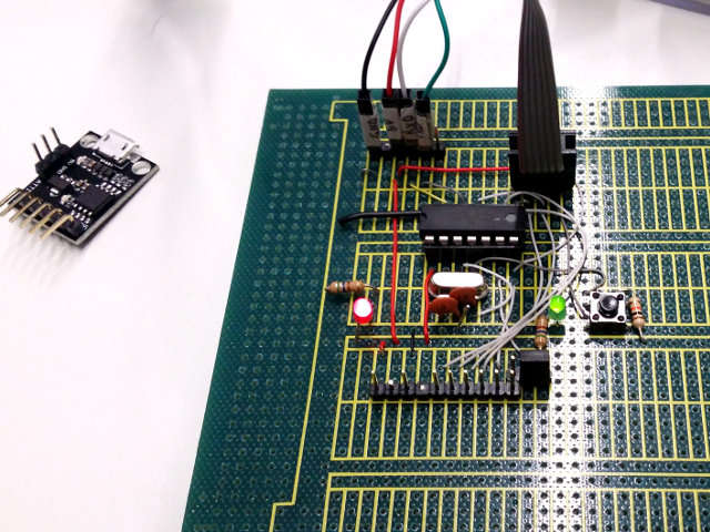
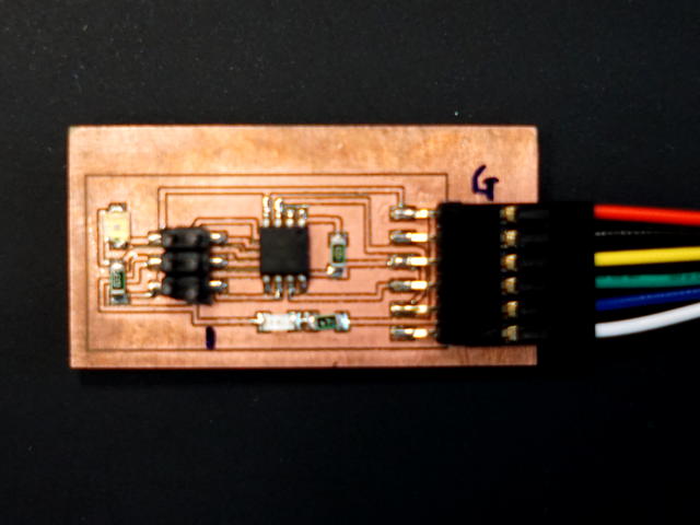
Completed ATTiny44A board
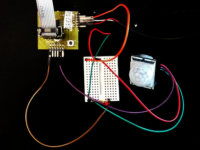
Testing PIR with FabHello board-
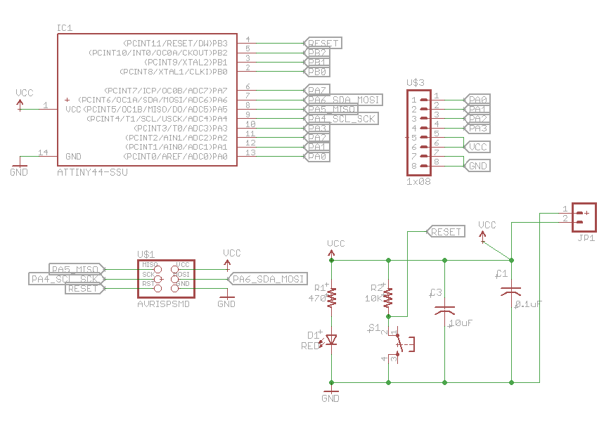
ATTiny44 input schematic
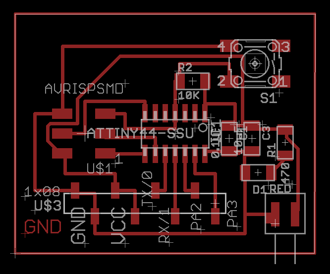
ATTiny44 input board
Files:
- Schematic: 10_ATTiny44_input.sch
- Schematic: 10_ATTiny44_input.brd
- Testing code: 10_PIR_input.ino
- A phototransistor changes its resistance based on the amount of light shining on it. We place the phototransistor in series with a 50 Kohm resistor or trimmer potentiometer between Vcc and GND. When light shines on the phototransistor, the resistance changes and hence with the use of Ohm's law, we can measure the change in voltage.
- Edward came to me with a board which was not working, based similarly on Neil's board, using the ATTiny85. We found out through tracing the circuit that a couple of the pins had dry joints. Also, a 499 Ohm resistor was also used, which gave very little changes in voltage (the readings always came out within the range of 800-1023). The exercise proved interesting as it used different mappings of the pins.
- I modified his circuit by connecting the ADC input to pin 2 of the ATTiny85 (Arduino equivalent A3) as well as an LED-resistor pair to pin 5 (Arduino equivalent 0, or MOSI). Pin 7 (Arduino equivalent 1 Tx) is used to send the serial value of the reading (using SoftwareSerial library) to indicate the readings done.
- An interesting feature of this circuit is that the ATTiny85 has only 8 pins and most of them are used. Here is a breakdown of the connections and multiple uses/functions of each pin
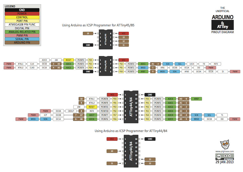
A good reference can be obtained from The Unofficial Arduino and ATTiny Pinout DiagramATTiny Pin Function Arduino equivalent 1 Reset Reset 2 ADC0 A3 3 ADC2 A2 4 GND GND 5 MOSI / Tx 0 6 MISO / Rx 1 7 SCK A1 8 Vcc Vcc
Note that the ATTiny85 does not use any external clocks, it can be programmed to work using the 1Mhz or 8MHz internal clock. - Before we start, we need to burn the Bootloader to tell the ATTiny85 which parameters we use. We set the processor to ATTiny85 using a 1 MHz clock, programmed with the FabISP board.
- The program initialises the SoftwareSerial and DDR to set the necessary pin functionality. On each cycle, the photoresistor is read and its contents transmitted using SoftwareSerial. To indicate that the program is still running and give some time for the photoresistor to recover, we include a blinking LED at the rate of 1 Hz
Also, the 499 Ohm resistor should be replaced with a 49.9K resistor to make the readings within the required range.// Using an ATTiny85 // Pin Configurations const int RX=0; // PB0 const int TC=2; // PB2 const int SENSOR = 3; // PB3 const int LED = 0; // PB0 SoftwareSerial mySerial = SoftwareSerial(RX, TX); int sensorValue = 0; // variable to store the value coming from the sensor void setup() { // declare the LED as an OUTPUT: pinMode(LED, OUTPUT); mySerial.begin(9600); mySerial.println("A Light Sensor"); } void loop() { // read the value from the sensor every 500 ms sensorValue = analogRead(SENSOR); mySerial.println(sensorValue); // Flash to say you are alive digitalWrite(LED, HIGH); delay(250); digitalWrite(LED, LOW); delay(250); }
Files:
- ATTiny45 Phototransistor board ( Schematic, Board Layout)
- ATTiny45 Phototransistor Sensor Input ( 10_at45_photoq.ino)
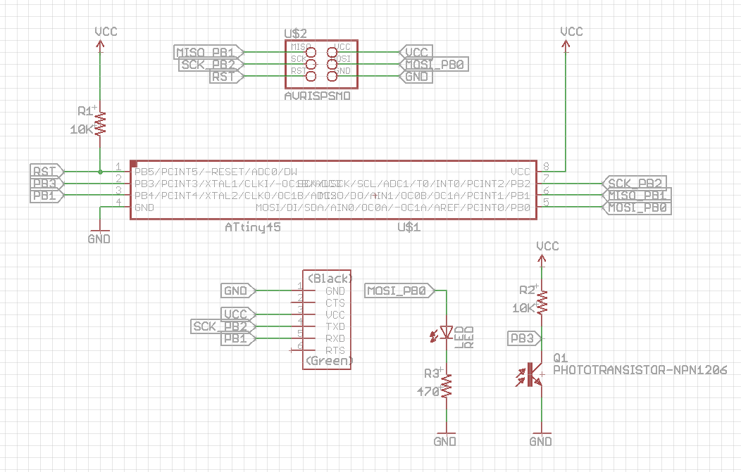
ATTiny45 Phototransistor Input Board
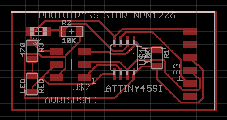
ATTiny45 board layout
ATTiny65 Phototransistor board
Reflection
- Building boards with Eagle is simple and very natural to electically trained personnel. It allows easy configuration and checking without having to wire up or experiment with the circuit. However, if we do not have a functional PCB router, the effort is wasted.
- Stripboarding/Breadboarding is a simple and efficient technique of configuring test circuits. However, you have to be neat and concious of how you work and how you wire. There are a number of nice tools to help you in the design and layout, the best I think for simple circuits is with Fritzing Libraries
- Building each microcontroller on a separate board elimiates the need for tedious wiring, however, if you are designing circuits from scratch, it is not an ideal way.
- The ATTiny85 with the 8 pin packages would be ideal to build small Internet of things projects. With 5 usable pins, we can still develop small applications.
References
- AdaFruit - PIR Motion Sensor
- Arduino and PIR Motion Sensors
- Fritzing - Electronics diagrams made easy
Not being of a artistic mind, I have shamelessly borrowed this template (simpleStyle_8) from html5webtemplates, in recognition of a simple, cool and functional webpage design.