
08 Computer Controlled Machining
Assignment
- Build something BIG
Journey
Steps towards a table- Draw the parts using AutoDesk Inventor, test assembly
Sort items to fit a 4x8 foot 0.5in plywood sheet
Export drawing to a STEP file - Use MasterCAM
- import the STEP file
- setup the substrate, mill values and surfaces
- add tabs to support the milled object
- generate the routing toolpath
- verify the toolpath visually
- export the Gerber NC code
- Convert the Gerber output to JG code for the SK2030
- Route/Mill the object
- Finish and assemble
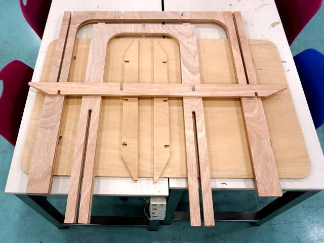
- The table consists of 4 leg sections, 2 short supports, 1 long support and the table top. According to the original designers, they could make it on a 4x8 sheet of plywood, so can I!
- In the design, the edges were chamfered to allow for easy fitting, the gaps/slots were made to 12mm giving space for the 6mm router bit access. Once designed, the table was test-fitted to check for errors.
- The entire 8 sections were laid out on the same plane to ensure that it could fit on a single sheet.
Once complete, the entire file was exported to a STEP output file.
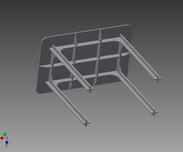 Inventor Stand-up table simulated
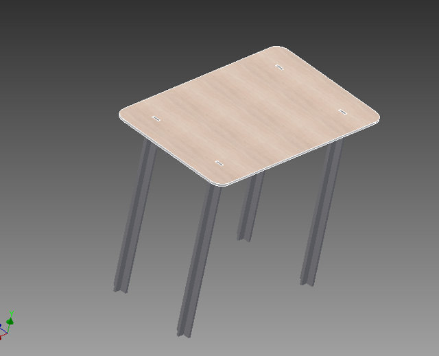 Inventor Stand-up table simulated
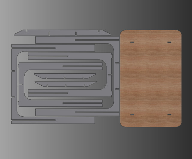 Parts required for the table
- Import the STEP file, the wireframe of the objects will appear on the screen. Use the FRONT, TOP, SIDE, ISO icons on the top menu to help layout the objects.
Important keys:
Middle Mouse Button - Rotate objects Alt-MButton - Move objects Alt-S - toggle solid/wireframe - Place the object on a slight ISO angle, and use Xform > Move Origin to place the origin on the TOP, LEFT-HAND corner of the object. It would be best to place the origin on the object.
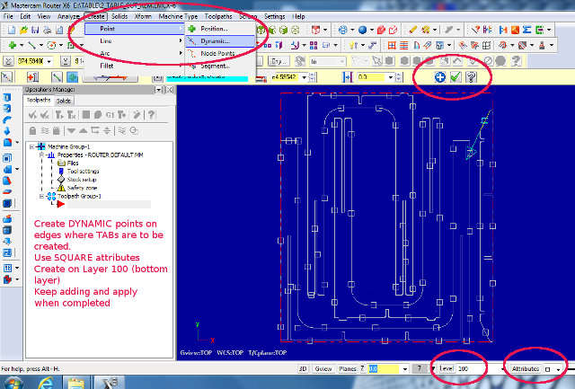
- To generate the tabs (small sections to hold the cut while milling), first create a layer 100. Rotate the object to show the bottem section (where the tabs are to be created).
Select Create > Curve and using the menu select the areas which the curve is to be generated on the bottom layer.
Use the Level to switch OFF all layers except the bottom layer.
Change the Attributes (next to Level) to a square.
Use Create > Point > Dynamic to add tabs on the bottom layer. You can use the ADD button to keep adding while changing edges. Click Apply to keep the tabs. - Use the Properties > Stock Setup (on left-hand window). Select "All Solids" and the graphic should show the depth of the stock that you are going to mill, verify the depth of the stock.
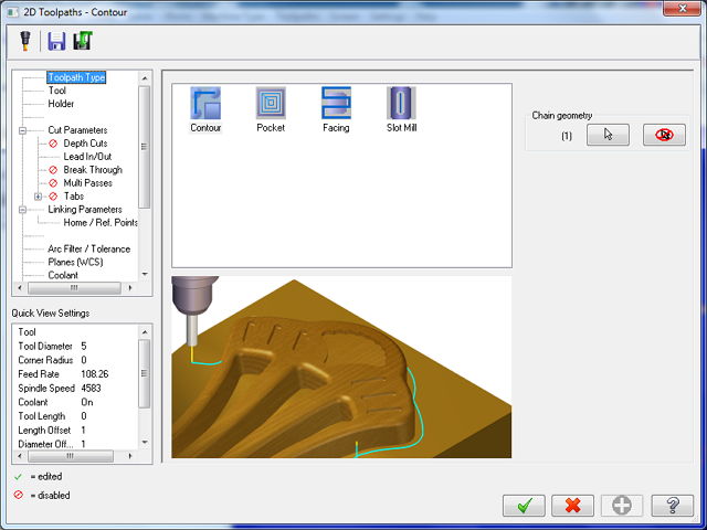
- From the top menu, select Toolpaths > Contour and select the wireframe/solid/face which you wish to mill. You can skip the selection of the bits to have a quick check to see how the router bit is to be inserted. From this diagram, the direction is correct as we can see that the bit enters from the top. If the direction is incorrect, select the reverse direction to correct. You can then delete this toolpath and start again if necessary.
- Use Toolpath pop-up to change the Tool to use. Typically for wood, we choose a 6mm Straight Bit with a Spindle speed of 1000 and feed-rate of 1000. Note that the SKC2030 does not change the speed at all and routes at a rate of 3000rpm.
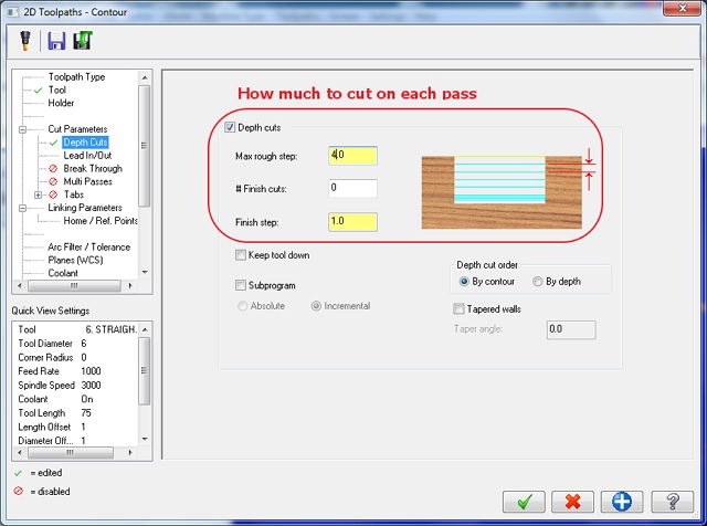
Enable Depth-cuts (how deep to cut on each run), and select 4mm. You can also specify a final cut which should be slower and of thinner value
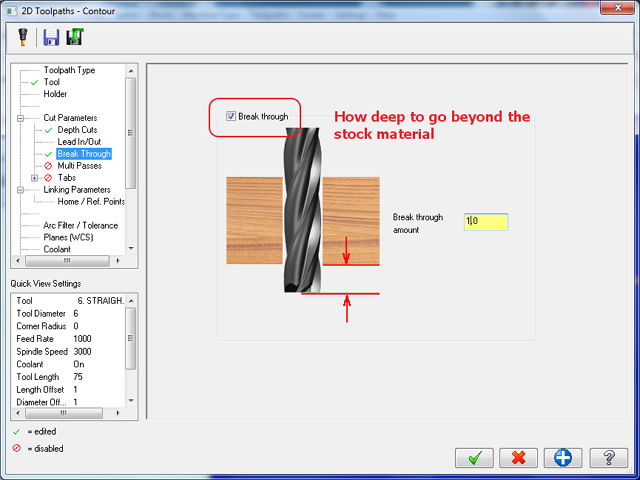
Enable Break Through (how much to go to cut through the material), specifying a depth of 1mm is sufficient. This would cut into the sacraficial board.
Enable Tabs using Manual and enabling square points to be used as tabs. A typical tab should be about 20mm x 3 mm. We remove these tabs after the routing by means of a chisel and hammer.
Finally select the Linking Parameters and enable all values to be absolute. This defines the movement of the mill bit across the board. - You are now ready to generate the toolpath. From the top selection, generate the toolpath. You can then view the simulation of the cut from this selection as well. When you are satisfied, click the next icon "G1" which generates the Gerber NC code.
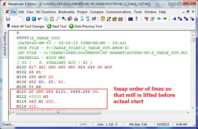
- A window pops up to allow you to inspect or make changes the code. In our system, we have observed that a set of codes near lines N108-N112 affect the lifting of the routing bit which scars the cut. Hence we change the lines to become the following order:
Original code:
    N110 G0 G90 G54 X141.446 Y-73.552 C0.
    N112 S1000 M3
    N114 G43 H3 Z50.
    N116 Z2.
to be re-arranged as follows:N109 G43 H3 Z50. N110 Z2. N111 G0 G90 G54 X141.446 Y-73.552 C0. N112 S1000 M3
We also change the last lines of the code to lift the mill (Z0 -> Z20) after cutting to lift the mill before returning to the marked origin,N498 G90 G49 Z20. M05 N500 G52 X0. Y0. Z20. N502 G8 P0 N504 G17 N506 M30 ... <end-of-file>The Gerber NC code is then saved. - We next execute the JGcode converter and use the Gerber NC code as input.
The JGcode converter converts the Gerber code into JGcode for the SK2030. - We are also presented with a graphical view on how the cut is to proceed. If satisfied, we save this file (has the extension .jg)
- The .jg file is then transfered to the root directory of a Thumbdrive which is then inserted into the controller of the SK2030 for cutting.
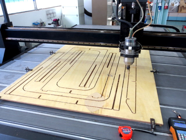
- The plywood stock is securely mounted on top of a sacrificial layer on the bed of the SK2030 using T-clamps. The correct mill bit (6mm) is placed into an appropriately sized colette and mounted securely on the router. The spindle is spun up to check that there is no vibrations or erratic movements.
- Using the controller, move the router head to an approximate position at the beginning of the route and press the XY=0 button. This will be the routers origin in relation to the route. Leaving the mill bit at a safe distances (Z) above the plywood, we can then perform a dry run to check the cut.
- When satisfied, the router head and bit is slowly lowered to the stock. A piece of paper is used to roughly check the gap between the bit and the stock. When the paper is just jammed between the bit and the stock, the Z=0 button is pressed to indicate the zero position.
- The JG code from the Mastercam output is then loaded from the thumbdrive and the routing is started.
- MasterCAM can be done offline (it's networked licensed) and this saves a lot of time if you know what you are doing. Most of my time was spent mastering the techniques and values in the CAM process.
- The Gerber NC code needed to be corrected, need to check whether this is a problem of MasterCAM or the SK2030 itself.
- Although the .jg code was generated, we did not have full control over the SK2030 e.g. Spindle speed, feed-rate was fixed and could not be changed. We need to contact the supplier to confirm as the manual did not have enough information.
- Plywood purchased was of low quality, giving unequal thickness, wood types and holes within the ply. it was sufficient to perform a rough cut but not as a finished product.
- This is a viable method of generating furniture for the FabLab and could be an ideal way of supporting the lab. Perhaps an automated method of creating the items could be done.
- Fun and very rewarding!
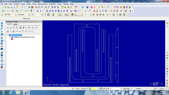
1 STEP file imported into MasterCAM
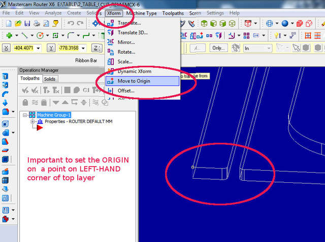
2 Setting the ORIGIN
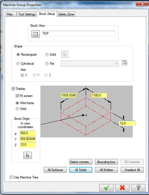
3 Properties of the Stock (Wood) verified
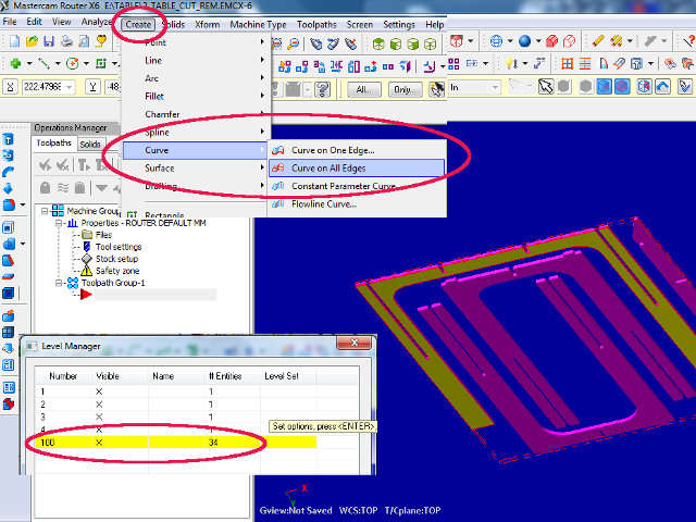
4 Creating Layer 100 for bottom curve
5 Using Points to indicate Tabs
6 Selecting tool Presets
7 Setting cutting depth per run
8 Setting break-through limits
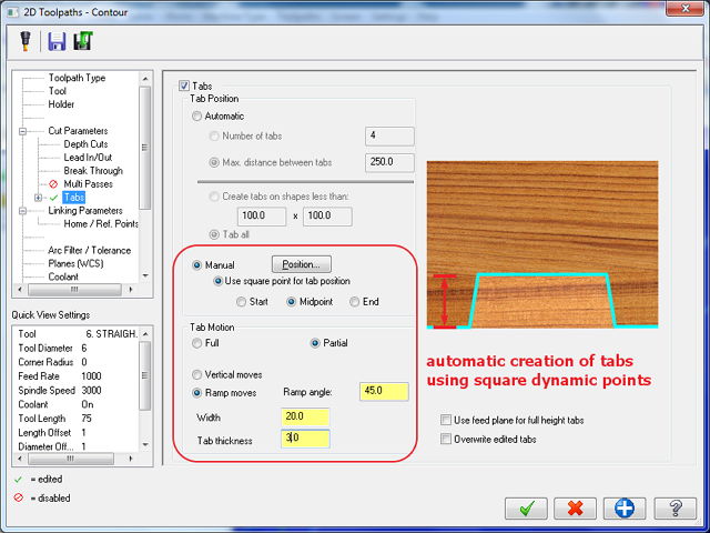
9 Tab Creation from points-
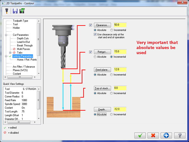
10 Setting tool linking parameters
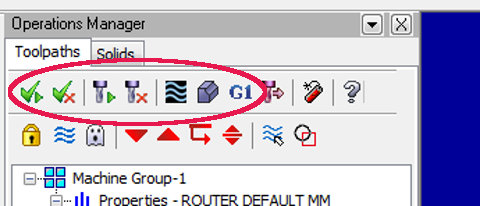
11 Toolpath generation functions
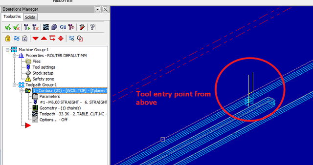
12 Check entry & path of Mill tool
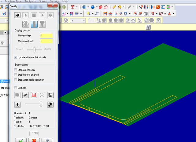
13 Simulate toolpath for check
14 Generate NC code
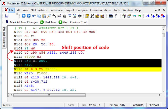
15 Gerber code corrections
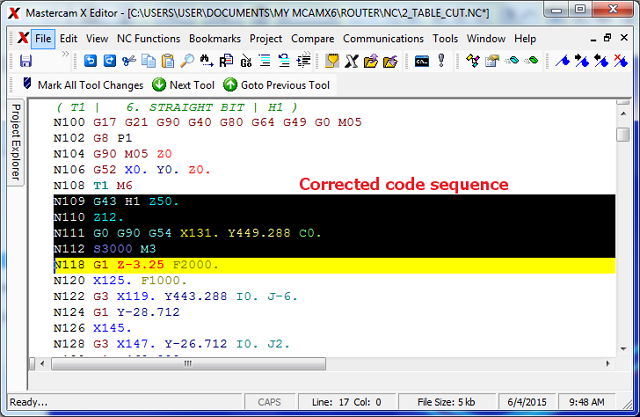
16 Manually Corrected Gerber Code
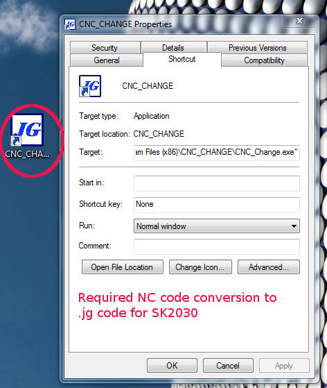
Conversion from Gerber NC to .JG
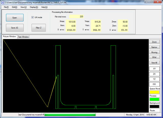
Converted to .jg with toolpath view for checking
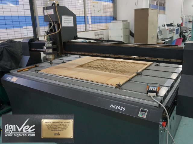 SignVec SK2030 Router
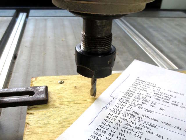 Zeroing the Z-axis using the paper test
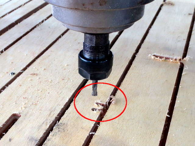 Router Entry and Exit points
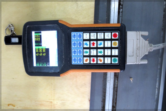 SK2030 Controller with thumbdrive code
 Manual removal of scrap while routing
 Routing completed
 Sandpapered & finished
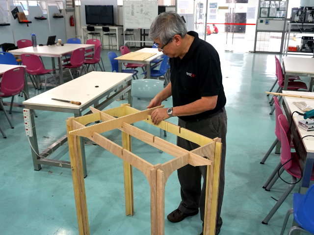 Assembling the table
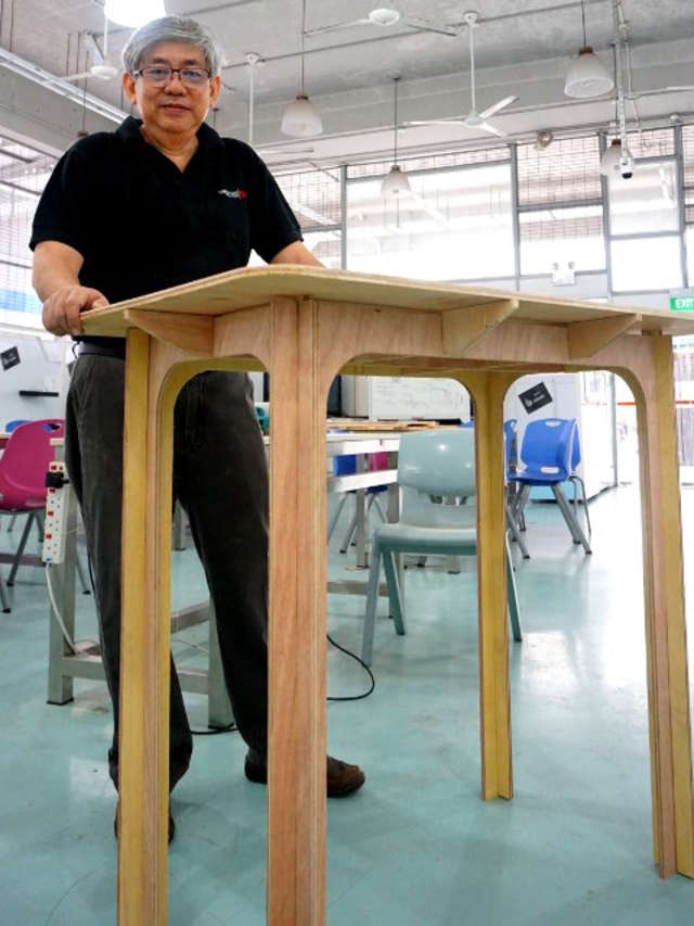
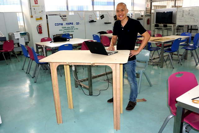 Roy test driving the table
Reflection
References
Not being of a artistic mind, I have shamelessly borrowed this template (simpleStyle_8) from html5webtemplates, in recognition of a simple, cool and functional webpage design.