
07 Embedded Programming
Assignment
- Read a microcontroller data sheet
- Program the ATTiny44 to do something with as many programming languages and programming environments as possible
Journey
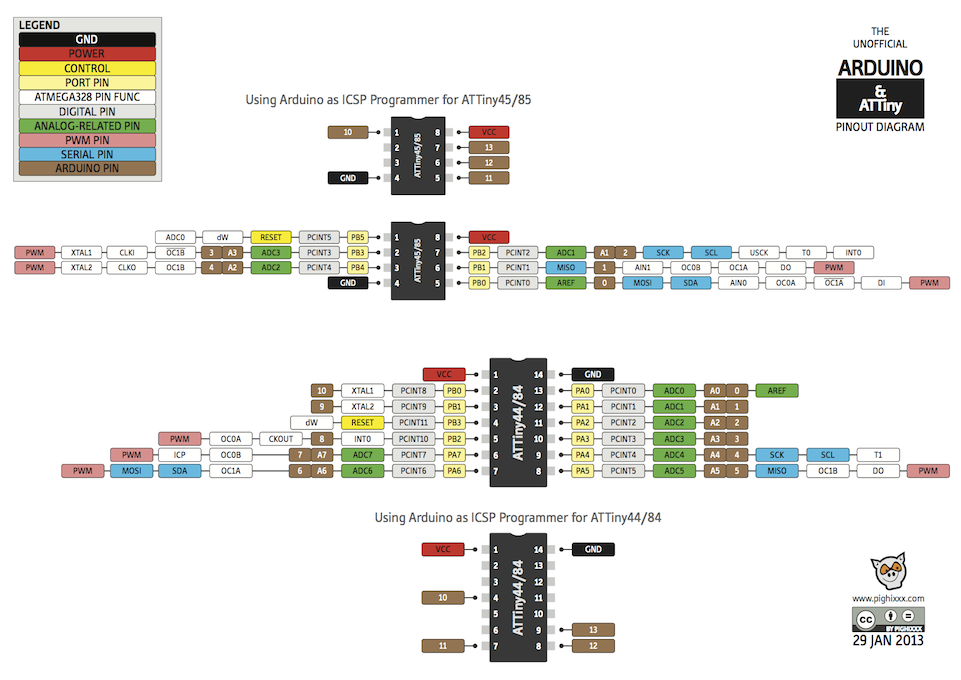
The FabHello board is built using the Atmel ATtiny44A microcontroller. The information on the microcontroller can be found on the following links:
The datasheet provides information on the pin configuration of the microcontroller as well as pin definitions which are used later for programming. In each section, it shows how the microcontroller can be re-configured for different uses by changing the configuration using programming.
From the datasheet, the ATTiny44 has some amazing characteristics:
- 8-bit microcontroller with internal 8MHz clock
- SRAM, Counters, PWM, Interrupts, ADC, reprogrammable flash memory
- Each port has its own internal pull-up resistor
- Multiple function ports e.g. digital I/O, PWM, TWI
- 8-bit and 16-bit counter/timers
- Universal Serial Interface (I2C)
- Analog comparators and ADCs
- Programmable configuration using Fuses
- Able to work at 1.8 - 6.0V
Developing Embeded Software
Required items:
- FabISP or any in-system programmer (e.g. USBasp)
- FabHello board with LED, Button and FTDI
- FTDI cable (essentially a USB to TTL-232-R)
Points to note about equipment
- A stable ISP is required. If the FabISP board is performing irregularly, it would be wise to use the soldering rework hot-air iron to ensure all points are soldered correctly.
- In building the FabISP or the FabHello board, it would be best add a power indicator LED, this would ensure that the board is powered and working.
- A FTDI cable converts TTL-232-R 5V signals to USB. Typically this cable should have the following signals: 5V, GND, TX and RX. Note that this cable is different from the USB-RS232 converter as it lacks the MAX232 chip that converts the TTL signals to +12/-12V as well as inverts them.
Check that the ISP programmer and the FTDI cables are working correctly.
Ubuntu 14.04% lsusb # ISP programmers Bus 005 Device 069: ID 1781:0c9f Multiple Vendors USBtiny Bus 005 Device 068: ID 16c0:05dc Van Ooijen Technische Informatica shared ID for use with libusb # FTDI/USB to Serial Bus 005 Device 070: ID 067b:2303 Prolific Technology, Inc. PL2303 Serial Port Bus 005 Device 071: ID 10c4:ea60 Cygnal Integrated Products, Inc. CP210x UART Bridge / myAVR mySmartUSB light
We first work with the Arduino IDE interface, which is the easiest. We need to download the Arduino IDE, install it. Next load the ATTiny definitions so that the IDE can recognise the board, and the FTDI drivers
- Download and install the Arduino IDE v1.6.3. The .tar file is extracted and the folder moved to the /opt directory
cd ~/Downloads
tar -zxvf arduino-1.6.3-linux64.tgz
sudo mv arduino-1.6.3 /opt
- You might/may need to install the java Runtime Environment, if you have not done so in the Ubuntu system.
sudo apt-get install openjdk-7-jre
- You need to give permissions to read and write the USB port, the port depends on how your operating system installs and assigns the port
sudo chmod a+re /dev/ttyACM0 (ttyS0 or ttyUSB0)
- Start the arduino ide using /opt/arduino-1.6.3/arduino (alternatively, you could create a link to the desktop and run it from there. From the interface, we need to find out where the IDE keeps the files. This is done with File > Preferences > Sketchbook Location
In my case, it is /home/rodney/Arduino
We need this location as we will place the ATTiny definitions here. - Download the ATTiny-ide drivers from High-Low Tech, choosing the correct IDE-1.6.X drivers. The file is expanded and the location of the ATTiny folder is noted.
- Restart the Arduino IDE and setup the parameters to handle the target board and the ISP programmer
- Tools > Board > ATTiny44 (external 20MHz clock)
- Tools > Serial Port > /dev/ttyS0 // depends on what you are given
- Tools > Programmer > USBTinyISP
- Next, burn the bootloader. Please read Installing an Arduino Bootloader to understand why you need one and why it is essential that you burn this to your ATTiny. You need to do this only once.
- I failed to write the Bootstrap at this point. I found out that I had to give superuser rights to access the writing of AVRdude. This can be accomplished by changing the udev settings, as shown in the tutorials.
To allow AVRDude sudo access to send the Arduino code over.
install uisp sudo apt-get install uisp Enable sudo access cd ~/Desktop gedit 10-usbtinyisp.rules --- SUBSYSTEM=="usb", SYSFS{idVendor}=="1781", SYSFS{idProduct}=="0c9f", GROUP="adm", MODE="0666" SUBSYSTEM=="usb", ATTR{idVendor}=="1781″, ATTR{idProduct}=="0c9f", GROUP="adm", MODE="0666″ SUBSYSTEM=="usb", ATTR{idVendor}=="1781", ATTR{idProduct}=="0c9f", GROUP="plugdev", MODE="0666" SUBSYSTEM=="usb", ATTR{product}=="usbtiny", ATTR{idProduct}=="0c9f", ATTRS{idVendor}=="1781", MODE="0660", GROUP="dialout" --- Apply to the udev rules sudo mv 10-usbtinyisp.rules /etc/udev/rules.d sudo service udev restart Unplug all USB devices and plug them back again - There were still some problems in writing the programs to the ATTiny, and this was reflected in the error message saying that AVRdude did not have the libusb linked into it at compile time.
The problem was with the Arduino 1.6.3 IDE which I believe has a fault with the AVRDude which comes with it. Solution
- Rename the AVRdude which came with Arduino to __Arduino (deactivate it). This is found in /opt/arduino-1.6.3/hardware/tools/avr/bin
- Install AVRdude seperately by compiling the source or from ppas:
sudo add-apt-repository ppa:pmjdebruijn/avrdude-release
sudo apt-get update
sudo apt-get install avrdude
- Change to /opt/arduino-1.6.3/hardware/tools/avr/bin and make a link to the AVRdude that you have just installed.
cd /opt/arduino-1.6.3/hardware/tools/avr/bin
ln -s /usr/bin/avrdude
- You are now ready to write your programs to test the board out. When you have complied your code, use File > Upload to board using Programmer.
- After writing a few programs to test the output (LED) and input (Button), I put together a program that combines output, input and the serial i/o.
The program creates a heartbeat pulse with the LED indicating that the program is running, when the button is pushed, the LED goes off for 2 seconds, and a message is sent to the Serial port. Every 5 seconds, a messsage is also output. If the user types a message, the message is echoed back to the port in uppercase.
// FabHelloTest.ino
// Every 500 ms flash the LED
//       200 ms check the BTN
//       1   s  output a message on FTDI

#include <SoftwareSerial.h>

// FabHello board pins
#define LED  7 		// Ard 7 ATT PA7
#define BTN  3 		// Ard 3 ATT PA3
#define TX   0 		// Ard 0 ATT PA0
#define RX   1  	// Ard 1 ATT PA1

// constants
// how long before we check: 0=LED, 1=BTN, 2=SERIALout
const long interval[3] = {500L, 200L, 1000L};  // ms

// Setup ftdi for serial comms
SoftwareSerial mySerial(RX,TX);    // RX, TX pins

// Variables will change :
int ledState = LOW;             // ledState used to set the LED

// Duration of time passed
unsigned long previousMillis[3] = {0, 0, 0};

// the setup function runs once when you press reset or power the board
void setup() {
  // initialize digital pins
  pinMode(LED, OUTPUT);
  pinMode(TX, OUTPUT);
  pinMode(RX, INPUT);
  // initialize serial port speed
  mySerial.begin(9600);
}


void loop()
{
  // here is where you'd put code that needs to be running all the time.

  // check to see if it's time to blink the LED etc; that is, if the
  // difference between the current time and last time you blinked
  // the LED is bigger than the interval at which you want to
  // blink the LED.
  unsigned long currentMillis = millis();

  for (int counter=0; counter < 3; ++counter){
	 if (currentMillis - previousMillis[counter] > interval[counter]){

	   // save the last time we worked on a part
	   previousMillis[counter] = currentMillis;

	   // count is up, check each counter
	   if (counter == 0){    // change state of LED
		 if (ledState == LOW)
		   ledState = HIGH;
		 else
		   ledState = LOW;
	   }
	   digitalWrite(LED, ledState);

	   if (counter == 1){    // check button switch
		 int btnstate = digitalRead(BTN);
		 if (btnstate == LOW){
		   mySerial.println("Ouch!");    // pressed
		 }
		 else
		   // normally print a dot
		   mySerial.print(".");
	   }

	   if (counter == 2){    // output a message
		 mySerial.println("I'm alive!");
	   }
	   // set the LED with the ledState of the variable:
	 }
  }
}
FabHelloTest Sample Output
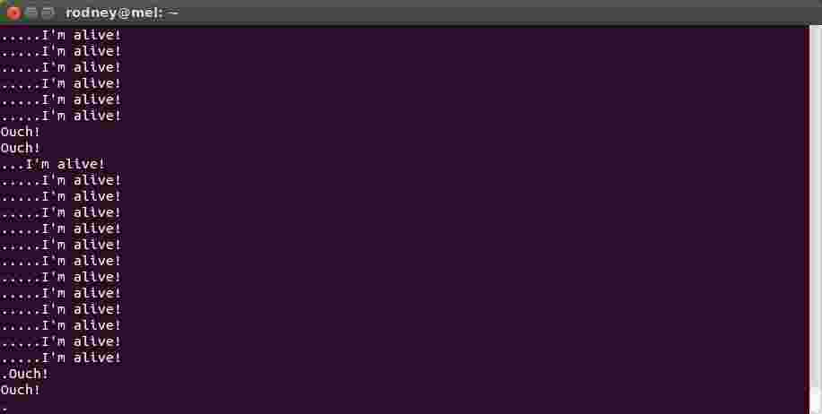
FabHelloTest Sample Output
Reflection
- The biggest problem we faced in programming the embeded system was whether our boards worked correctly. In retrospect, if I would design the FabHello board again, I would put in a LED to indicate that power was being supplied to the system.
- The second problem we faced was the FTDI cable which was not currently on hand. We tried to make do with the USB-RS232C interfaces, but soon realised that we were dealing with an inverted signal within -12/+12V ranges. In the interim, we purchased some USB-TTL interfaces, however, this proved to be ineffective in Windows 8.1 environments as the drivers were outdated.
- The programming of the embeded system was quite easy with the Arduino IDE, however, if you started using objects e.g. String, you would soon run out of memory space.
- Using makefiles and AVR-Cpp was intimidating in the beginning but soon, this proved to be a more efficient method.
References
- Arduino Program Language Reference
- Adafruit Raspberry Pi, Arduino and ATTiny Projects
- High-Low Tech - programming an ATTiny with Arduino IDE (v1.0.x ~ 1.6.x)
- AVR Tutorial by Lady Ada
- AVR Library
- 42bots Hobby Robotics and Electronics with Arduino and Raspberry Pi
- Makefiles - A tutorial by Example by MrBook
- Wikipedia Makefile
- Fab Academy Embeded programming makefiles tutorial
Not being of a artistic mind, I have shamelessly borrowed this template (simpleStyle_8) from html5webtemplates, in recognition of a simple, cool and functional webpage design.