
05 3D Scanning & Printing
Assignment
- Design something small in 3D and print it using a 3D printer. The output should show some capabilities of 3D printing.
- Scan an object in 3D and if possible print it.
Journey
3D Design and printing
After looking at some YouTube videos and sites, it is clear that 3D printing allows you to create an entire object in a 3D design world and implement it using 3D printing. Some ideas came to mind, which I thought would be interesting and could only be done with a 3D system. These included:
-
A rotating birdcage on a stand
The birdcage would use a cylinder collar to be connected to the stand. The connection would use a ball-and-collar which would be 3D printed with a small gap (e.g. 1mm) between the ball and collar, which would be re-enforced with printing supports that could be broken after printing.
This idea was abandoned as the stand would be a bit to thin and difficult to print without sufficient support and reliability of the 3D printer. -
A worm gear
I was sufficiently intrigued by this example (http://Youtubelink.com) to do some reading into the design of the worm gear and drawing of the item. I abandoned this idea as it grew a little too complex, in terms of mechanical engineering, for me to attempt within 3 days. However, I intend to put this on my todo list when I have more time.
The following references would definitely help:
-
Cable management device.
Since I am going to use the 3D printer, I might as well make something useful and at the same time exercise my skills with Inventor. I came across a site showing a number of cable management systems and decided to develop one for my use based on the Gear Wrap example shown here.
3D Conceptualization
Working with the images I had on the site, I started to make plans on drawing the cable keeper
using Inventor. From previous drawings, I found that thinking out the problem and working it
on paper would be best.
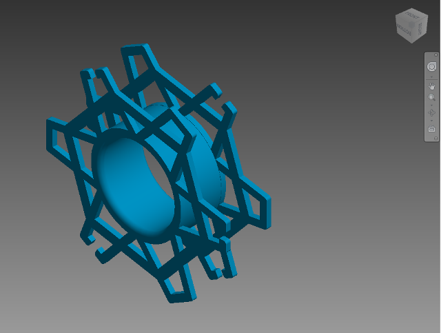
- Inner diameter 40mm, outer diameter 80mm, side thickness 2mm, strut width 3mm, gaps for cable 2mm, top of "A" 6mm, base is equally divided around the circle.
- After drawing a single "A", use the circular replication to draw the rest
- Make a copy of an "A", copy with offset of 60 degrees, break the top "A" and replicate.
- Extrude object by 2mm to obtain one side.
- Extrude the centre hub using 2 concentric circles
- Create a new plane and project the object and extrude to get the other side.
In FabLabSP, we have a lot of Makerbot Replicator 2 systems which in the past had problems in printing projects. I selected a machine that seemed to give the least amount of problems to use to implement the print. At the same time, we are evaluating some 3D printers for the next procurement and as luck would have it, we have an Ultimaker2 on loan. Hence, I decided to use this opportunity to conduct a comparison between the two printers.
| Task | MakerBot Rep 2 (MR2) | Ultimaker 2 (UM2) |
|---|---|---|
| Machine setup | Selected system which seems to be printing well, one of the staff was making small balls with different coloured material using manual feed and changes. According to the user, it was the best way and he could change filaments of different colours without problems. | Test prints showed a better quality than the MR2. We had problems with the
filament feed, and spent a better part of an afternoon fiddling with the feed
(this was done with a stepper motor and mechanism at the rear).
In the end, it mas a matter of adjusting the tension to prevent excessive gripping
to the filament. The UM2 uses an intelligent feed and retract system of the filament when printing. |
| Filament type | 1.75mm PLA Feeding of the filament was manually done, I was advised to cut a length of the filament (after calculation from the printing program) as the feed from the reel causes problems. However, in the actual printing, this did not seem to cause any problems |
3.0mm PLA Feeding of the filament is done by a gripper and stepper motor. The printer has an option to eject/feed the filament which has tension from the feeding element at the back. The feed has to be "tuned" to give an optimum feed without excessive griping of the filament. |
| Printing plate | MR2 has a lot of problems with the base plate and removal of printed objects
with a scraper resulting in torn base material (Teflon, I think). We solved this
by using Paper Masking tape which served its purpose well and could be replaced
each time the printing is completed. Surprisingly, this is a cheap and effective way of coating the plate |
UM2 has a heated base plate. To prepare the plate, it is first cleaned with water and paper towels and wiped day. Using the instructions in the manual, a coating of glue from a glue-stick is applied on the surface. According to the supplier, using UHU or better branded glue sticks give better removal results and adhesion results |
| 3D Object Preparation | MakerBot Desktop This software is downloaded from the MakerBot site. It allows you to place the object in relation to the printing platform. I had used this software before (about a year ago) and this is the improved version which allows placement and viewing. This new version of software is much easier to use than the older version. Once the object is loaded, it can be prepped for printing. |
Cura This software is open source and downloaded from the Ultimaker site. This software is very easy to use, it allows you to place the object, rotate or mirror it. I was fairly impressed by the way I could position the object for printing (flatten on platen). It is definitely easier and far more superior than the MB Desktop. I used this software to flatten the object and exported the result to a .STL file which I then used for the MB2 desktop layout. 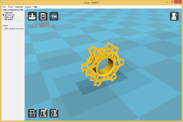

|
| Output for printing | MB Desktop creates a .x3g file for the MB2. This file can be saved on the system or exported to a SD card for insertion into the printer. | Cura generates g-code for the UM2. Setting up for the different options, I believe you can output code for the MB2 as well. This file can be saved on the system or exported to a SD card for insertion into the printer. |
| Printing Options | Rafts: Yes Supports: Yes Normal print settings (default) Estimated time: 1 hr 50min |
Rafts: No Brim: Yes Supports: Yes Normal print settings (default) Estimated time: 3 hr 20min |
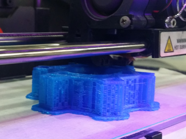
| Printing Operation | The MR2 performed flawlessly (!!) this time, however, 3/4 into the print with 85% completed, the filament broke. Printing was paused and the new filament inserted without problems. | The UM2 made a couple of false starts with the extruded filament not adhering to the plate. After 3 tries, it too started printing flawlessly. |
| Printing with supports | The supports generated by MB Desktop looked excessive and an overkill.
There was a lot of webbing produced, however a final print was successful. Total print time: 1 hr 45 min |
The supports generated by Cura looked thin and manageable in comparison to MB,
it used small rectangles to support the 3D object. The final print was successful. Total print time: 3hr 15 min |
| Removal from plate | We had to remove the masking tape to remove the final object. The base of the object was not smooth and had markings from the tape. No scraper was used. | A plastic scraper was used to dislodge the brim, after that the object was removed without problem from heated plate. |
| Printed object clean-up |
 Removing the structure support was a nightmare, using pliers and cutters,
it took almost 30 minutes to see the final product which still had webbing and
print-overs. I had to use a rats-tail file and after 2 hours managed to remove
most of the redundant filaments. The final product still needs surface
finishing work.
Removing the structure support was a nightmare, using pliers and cutters,
it took almost 30 minutes to see the final product which still had webbing and
print-overs. I had to use a rats-tail file and after 2 hours managed to remove
most of the redundant filaments. The final product still needs surface
finishing work. |
 Removing the structure support was simple. The support was crushable
and removable by hand, though a pair of long-nose pliers made easier work.
Final product looked good and smooth, though there was some work to be done
to clean up the object. All-in-all a better and more pleasing product created.
Removing the structure support was simple. The support was crushable
and removable by hand, though a pair of long-nose pliers made easier work.
Final product looked good and smooth, though there was some work to be done
to clean up the object. All-in-all a better and more pleasing product created. |
Problems with 3D printing
- Printing is affected by a number of enviromental factors: air, humidity, temperature. We found that even a fan blowing onto the 3D printer affects the output tremendously.
- The choice of the filament also poses a problem. Although it may come from the same supplier, we are not guaranteed the batch or manufacturer of the material as most material have their own "printed" labels.
- 3. A choice of 3D printer code software determines how the 3D object is printed (and supported). You either take the time to build your own supports or use a better (paid) software to handle the printing. We have ordered Simplify3D which seems to give good performance and results (from what is discussed on the internet). Simplify3D costs US$149 (online) and SGD $200 from our local supplier. I will try to update this blog once I get some results on the printing.
- 4. A job may terminate/abort halfway into the print for practically no reason at all. It is very frustrating to wait for a 3hr print and to discover that the print aborted in the 11th hour. Sometimes it may be worthwhile breaking down the object into parts and combining the parts, however, this defeats the purpose of a 3D prototype print.
- The 3D printer should be treated as a High-Precision Tool and as such "care and concern" should be applied in quantity!
Conclusions
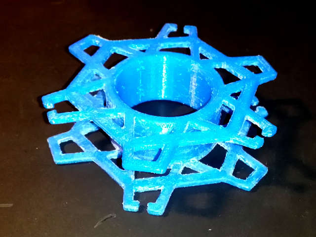 Makerbot Replicator 2 completed 3D print
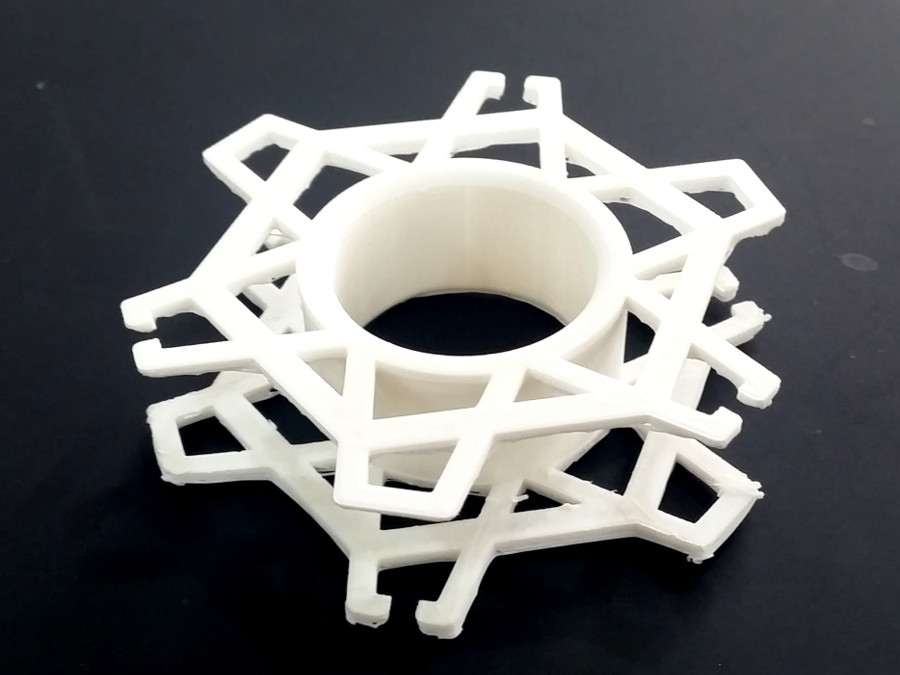 Ultimaker 2 completed 3D print
I was very lucky in obtaining two perfect 3D prints. I tried repeating the print
using the MR2, however it was unsuccessful in both times, having the print aborted
in the middle of the print. It seems more than "luck" had a play in it.
After some finishing, the 3D print was pefectly usable and performs as expected.
3D printers should be treated more carefully and are easily prone to misuse leading to
bad and aborted prints
 Cable keeper in practical use
3D Scanning
The second part of this week was to create a 3D object from scanning techniques. At FabLabSP we have the Microsoft Kinnect system setup for 3D scanning, however, this system was inoperable as it was under maintenance. Hence, I resorted to using Autodesk 123D catch system which involves taking a number of photographs either using a mobile device or digital camera and entering the information into the cloud system for processing.
1st Attempt: Flash Gun Unit set on turntable
In the first attempt, I thought it might be easier to place the object on a lazy susan
(aka turntable), surround the object with a matt background to distribute the lighting
and take multiple photographs while turning the turntable around.
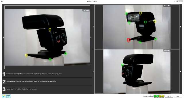
The result was a disaster a 123Catch could only recognise partial photos and had asked
me to identify the key points of the object.
Here are the errors in my work
- Lighting was constant and the object (Flash gun) was black in colour, this confused the patching software where it could not identify the edges or component parts of the object. The software required me to manually map the edges which ended in error.
- Lighting was constant and the object (Flash gun) was black in colour, this confused the patching software where it could not identify the edges or component parts of the object. The software required me to manually map the edges which ended in error.
- Having a plain background confused the stitching software as it could not record
reference points. I found out by placing coloured objects in the foregound helped
but could not completely stitch the 3D scan.
I used an autofocus camera set on intelligent mode (auto setting of speed, aperture and ISO) which further confused the stiching software. A fixed focus camera or set on fixed focus would be better as the distances could then be calculated by the software.
2nd Attempt Dysan Vacuum cleaner set on box, in shade outside laboratory
In a second attempt, I chose a Dysan vacuum cleaner (about 75x30x30cm) and placed
it on a box in the shade between the FabLabSP buildings. This time, I started taking
photos by moving around the object. The photos were taken at two angles, one at object
level and the other slightly above the object. Again after uploading, the stitching
did not turn out a complete 3D object.
The errors in this case were
- The object was too far away compared to the size of the photo, hence the definitions were lost.
- Atlhough the photos were taken in the shade, there were areas in the background which had a higher contrast in light and this distrupted the stitching process. Constant even lighting on the object as well as the background is important.
- Distracting imagery in the background. Although there was contrast in the object as well as the background, there were distracting features in the background which distorted the actual object.
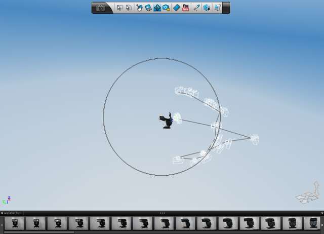
3rd Attempt: Fire Extinguisher
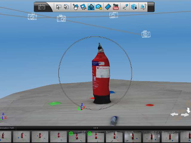
In this attempt, I tried to eliminate most of the errors made in the previous 2 attempts.
The object was placed on the floor with the following parameters:
- The object was placed in an evenly lit location without any contrasting features.
- 4 objects of different colours/shapes were used to identify and help the software stitch the photos together.
- A fixed distance was used to take the photos, this was done by drawing an imaginary circle around the object and taking photos from that circle.
Unfortunately when stitched together a part of the object did not appear on the final construction. It showed a bulge in the object which indicated that some photos could not be registered in the construction.
Points to consider when performing a 3D scan
- The object should be small (about smaller than the size of a shoe).
- The object should be placed on newspaper or some large printed text so that registration points can be easily obtained (a hint given by the AutoDesk demonstrators when using the Kinnect Scanner).
- Fixed focus should be used, preferablly taken at an angle of 15-45 degrees looking downwards on the object.
- Shaded lighting without high contrasts should be taken into consideration. The background should not have high contrasts as well.
- About 20-50 photos should be taken at differenter positions around the object at at least 2 varying angles. Note that 123Catch can only upload 70 photos at each time (and it is slooooow!)
- The object should have constrasting colours. Items that are totally black or having a singular colour will cause problems with the registration.
In the above attempts, I had been using a camera with a 24M pixel resolution and then
reducing the photo to a 1280x768 resolution. This reduces the size of the photo and increases
the upload speed of the scans. 123Catch only takes 70 photos at a maximum upload, and even with
50 photos at 100KB/photo took at least 10-15 minutes to upload the photos.
I am unsure whether the change in resolution affects the processing of the 3D scan.
Reflection
- Autodesk Inventor is definitely the drawing tool to use in creating 3D objects.
The design, creation and implementation of the object is accurate and clean.
I had no problems with the objects created and no errors were identified when parsed
through a STL checker.
Google SketchUp, although a simpler drawing program produced a number of hidden surfaces which caused problems in the printing. - In order to print a 3D object, you will need to generate the actual printer code (G-code for Ultimaker2, .x3g for MakerBot Replicator 2). Software is usually provided by the vendor, however, there are better software e.g. Simplify3D which allows for better control and placement of support structures which make the final object easier to print as well as minimizes the amount of waste material that needs to be removed.
- Enviromental factors are very crucial to the final printed outcome. Any changes may cause the print to abort or have errors. 3D printers should have enclosures and placed in stable locations away from vibrations. However, the systems are open and in use by a myriad of students with different skills categories and prone to abuse and misuse. A better guidance system should be implemented before printing is done.
- 3D printers should be treated like "hihg-precision" equipment - with gentle hands!
- In order to produce a perfect print, you need time to review the parameters of the print, the placement of the object for the printing, the placement of the supports (or placing your own supports) and tolerances of the print.
- I was not successful in 3D scanning, however, given the correct conditions and practising more often may produce some success in the scan. I will revisit this when the Microsoft Kinnect and our new 3D scanner comes into operation.
References
Not being of a artistic mind, I have shamelessly borrowed this template (simpleStyle_8) from html5webtemplates, in recognition of a simple, cool and functional webpage design.