
04 Electronics Production
Assignment
- Mill the FabISP board
- Solder the components onto the board
- Program the board as an ISP
Journey
Creating the FabISP Printed Circuit Board- The FabISP board is an electronic circuit with a feature that allows programming of microcontroller chips in their own system's production. The ISP board has a microcontroller (ATTiny44). Once the board is built and tested, a program is then downloaded onto the FabISP board allowing the board to operate as a programmer for other ATTiny boards.
- The FabISP board is provided by the course as a PNG file with the traces, however, we do not have the resources to mill the board directly using the FabLab modules
- We do have a dedicated PCB milling system using the LPKF Promat S103 which is controlled by CircuitPro. Basic operating instructions require the use of gerber file input, usually generated using Eagle.
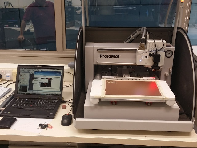 PC Board Plotter LPKF Promat S103 operations
 - With the schematic, we closely followed the layout of Neil's board and created a similar schematic and layout. We also increased the thickness of the traces to help with the production and milling of the board.
The following were created:- EagleCAD components: fabisp.sch, fabisp.brd
- Schematic layout: fabisp.pdf
- LPKF Gerber files: fabisp.cmp, fabisp.otl, fabisp.gpi
- The first PCB created was using Andy Bardagjy's design with the USB key. The mill was successful, however we soon discovered that the ground plane (signals) were missing from the board, so we abandoned the build.
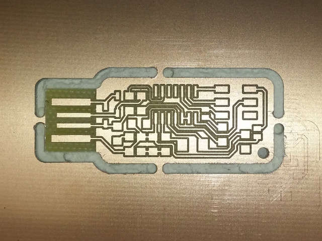
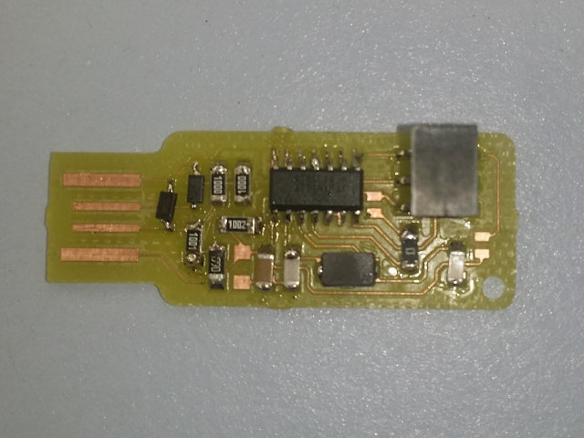
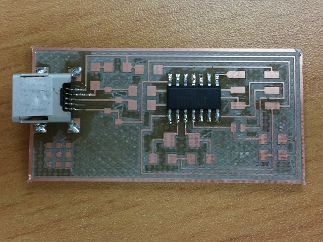
- A second PCB based on Neil's board was created and checked. This board has 2 jumpers (0 Ohm resistors) as well as fuses (we used wire-wrap wire) and created the board. Soldering was done with the help of a super-thin bit and a temperature controlled soldering iron. The soldering did not prove too difficult except that a third hand is required to hold the component in place while soldering.
- Once the board is soldered we attempted to program it using the instructions in the tutorial. We checked the board against the driver list and it showed that the board was detected but not recognised. Upon loading the necessary drivers we found the board to be working and could be used as an ISP programmer.
 FABISP key milled using LPKF
 FABISP key ground missing
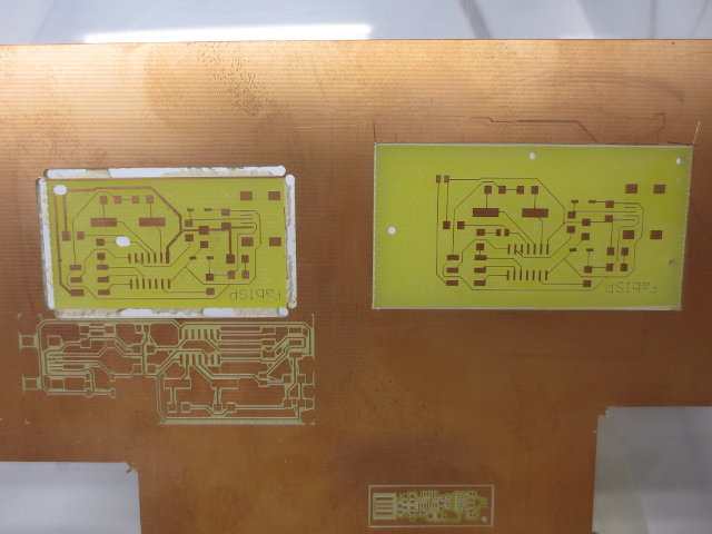 Milling attempts, positioning problems
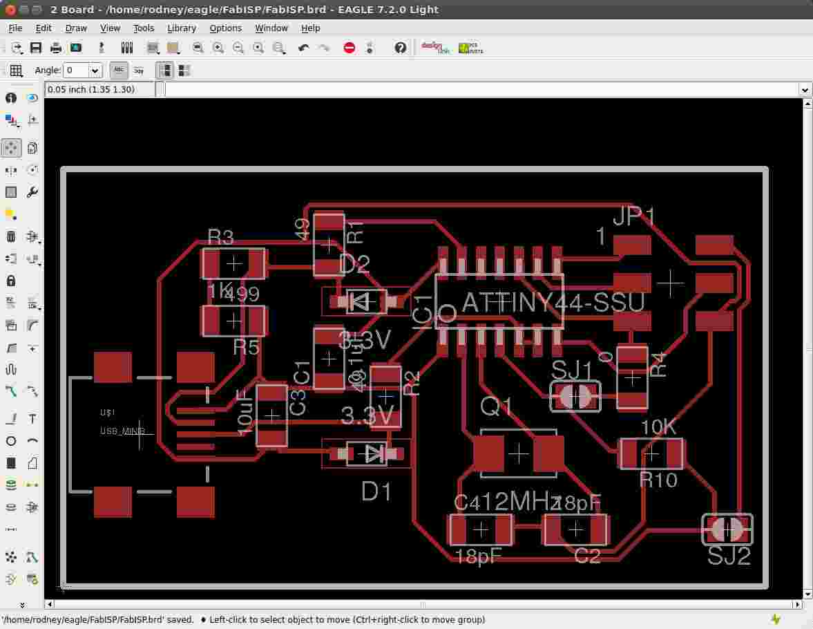 FABISP board layout
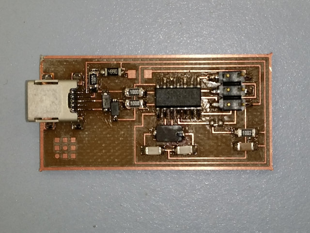
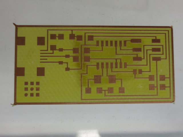 FABISP milled
 FABISP using Neil's board
 FABISP soldered
Programming the ISP
- In order to make the FabISP work as an ISP (In-System Programmer), we need to program it with the necessary Firmware. We could have done this with an Arduino (Ref: Using an Arduino as an ISP) or obtain a dedicated ISP.
- Feeling very rich, I decided to purchase one from AliExpress at the cost of US$1.95 which is USBasp compatible
- Next, since I was using a Windows 8.1 system, I need to download and install the USBasp drivers (also found on Thomas Fischi site). Instructions are provided there to by-pass the digital signature check on Win 8.1. Follow them.
Once completed, you should see the USBasp on the device-manager list. - I downloaded and installed WinAVR using the instructions on the site. WinAVR will setup the necessary paths for the software. You can test the installation by opening a CMD window and typing "avrdude" to examine the response.
- Next, we need to download and extract the FabISP firmware. You will find a folder "fabISP.mac.0.8.2_firmware" (it was developed on a MAC). The file of importance is "main.hex" which contains the firmware.
- Open a CMD window and navigate to the folder containing the firmware files. Steven helped me program the FabISP using the command-line avrdude instead of going through the make process.
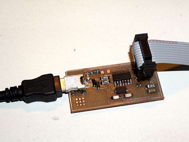
- Connect the USBasp (ISP) to the FabISP using the 6-way cable, ensuring that the pins are correctly matched, based on header positions. The FabISP should have the fuses in place (one for Power, and the other for programming).
- Before programming, we need to check the fuses on the FabISP board, using CMD
avrdude -v -v -c usbasp -p t44
	-v -v       be very verbose, show everything
	-c          programmer name (type xxx to have a list)
	-p          part number (t44 is for ATTiny44)
The above will give you information on the state of the microcontroller and the fuses for checking. You can find more about the command from the AVR Tutorial: Starting with avrdude.
You can check the use through the AVR Tutorial site.
The ATTiny fuses can be calculated and verified using Engbedded Atmel AVR Fuse Calculator site. - After verification, we are now ready to program the FabISP
avrdude -c usbasp -p t44 -v -v -U lfuse:w:0xff:m -U hfuse:w:0xdf:m -U flash:w:main.hex:i
	-v -v               be very verbose
	-c usbasp           use usbasp as the programmer
	-p t44              target processor ATTiny44
	-U                  memory operation
	lfuse:w:0xff:m      low fuse, write value 0xff, memory
	hfuse:w:0xdf:m      high fuse, write value 0xdf, memory
	flash:w:main.hex:i  flash write, file: main.hex, intel format
AVRDude Sample Run Output - Unplug the USBasp and the FabISP board. Remove the jumper right below the 6-way header (for programming) and insert the 0 Ohm jumper for Power.
- Open up Device Manager (Windows), and plug in your FabISP board. If sucessful, you should see the device USBTiny show up as one of the devices.
- If we had the correct milling system, the process would have been easier using the Roland Modela milling system. The Roland Modela system was also not operational at this time.
- The LPKF dedicated system was simple to use as a step-by-step process was provided. The problem with using the dedicated system is that the position of the board for cutting is not exact/tuned by the supplier. Although the system had an onboard camera, positioning the mill for economic cutting of boards is difficult.
- We had initial apprehensions regarding the soldering of the components, however with the correct soldering bit and temperature control, the soldering was simple, although in times a "third" hand is useful in holding the component in place (my hands were used to hold the soldering iron and the solder!)
- Identification of the components were simple, provided we did not remove them from the SMD packaging until we were ready to solder. The most difficult component to solder was the Zener Diodes as the identification of the cathode was only indicated with a light line on the component, which was difficult to see even under magnification. We decided that a hat magnifier would be ideal for this purpose
- We later obtained solder paste which was useful in the soldering, however this required the use of a heat gun. Using the data for the solder (Pb63/Sn37) we found that the melting point was 183 degC, the ideal settings for the heat gun was 230 degC and the soldering iron 200 degC.
- Programming the FabISP wasn't as difficult as I assumed. However with the ridiculous cost of the USBasp at US$1.95 leads me to question the need for making such a board, even as an exercise. A better board for beginners would be a simple I/O board with LEDs and switches that can be connected to a microcontroller, the board can be checked using a multimeter and can also be programmed with visual results.
- David Mellis FABISP with schematics
- CADSoft Eagle PCB Design Software
- Sparkfun - How To Install Eagle
- PC Board Plotter LPKF Protomat S103
- WinAVR
- AVR Tutorial
- USBasp - Thomas Fischi
- AliExpress online site
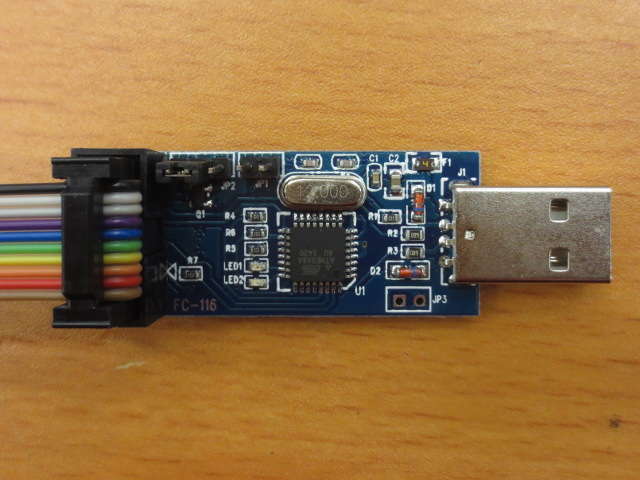
US$1.95 USBasp In-System Programmer
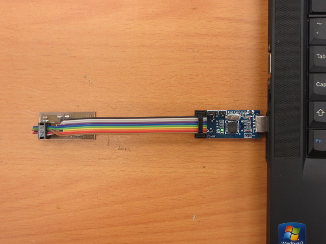
USBasp with target FabISP
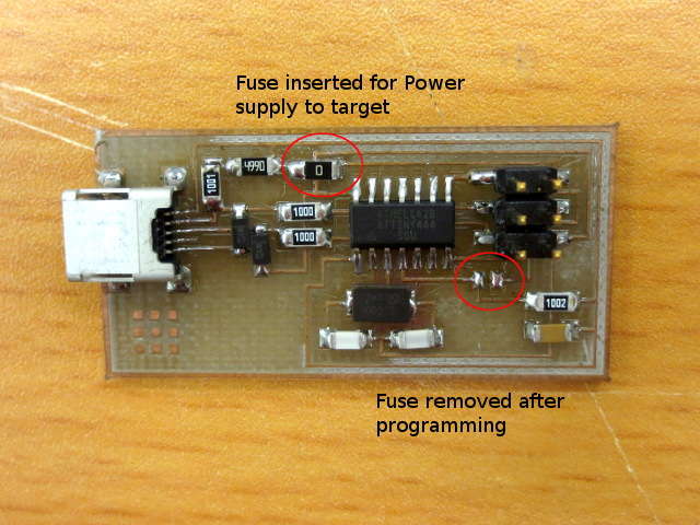
FabISP with fuses removed/inserted
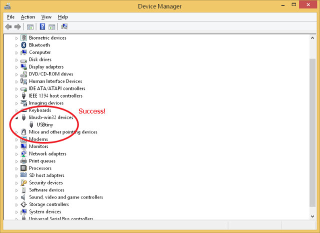
FabISP programmed successfully
Reflection
References
Not being of a artistic mind, I have shamelessly borrowed this template (simpleStyle_8) from html5webtemplates, in recognition of a simple, cool and functional webpage design.