Redraw the echo hello-world board, add (at least) a button and LED (with current-limiting resistor), check the design rules, and make it. Extra credit: simulate its operation.
How to design a circuit board with DipTrace
I had problems with FabISP and I knew Eagle a bit so to learn something new I used DipTrace to design FabISP (it's more complicated than redesign of hello-world board):
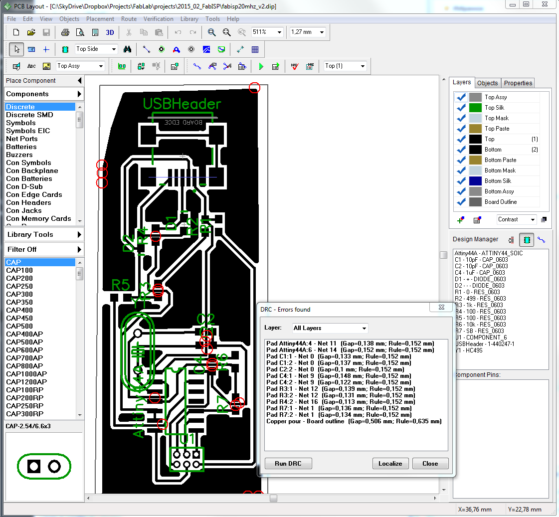
I had convert schematics to board and place components and wires:
The problem is that spaces between pins is too small so it couldn't pass Design Rules check and couldn't be made with my 0.4mm tool :(
Using DipTrace you can export board to almost any possible file format (and to g-code also) or order it:
I used Eagle software to design hello-world board with a button.
Original design (from Fab Academy archive):
My design: Source file.
Bill of materials:
1 ATtiny 44 microcontroller;
Resistors: 1x 499 Ohm, 2x 10KOhm;
Capacitors: 1x 1uF;
1 LED;
1 4pin button;
1 crystal resonator 20MHz;
Pins: 1x 2x3, 1x 1x6.
Firstly I started with schematics and used libraries to add components.
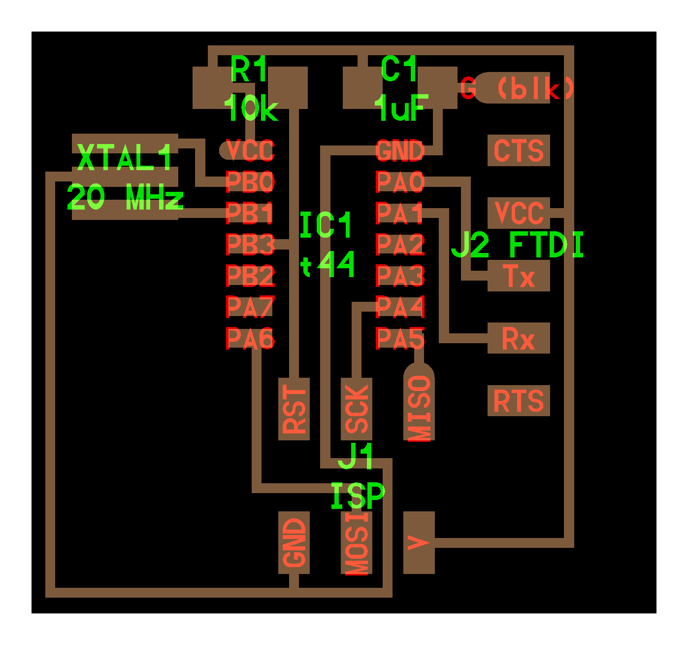
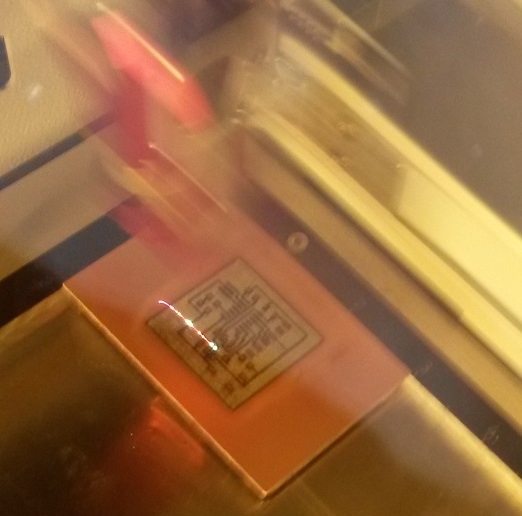
To make this plate I used the same technology, as Polina: laser engraving. I exported board as Image in Eagle without any preprocessing. So I obtain an image with all labels and pins:
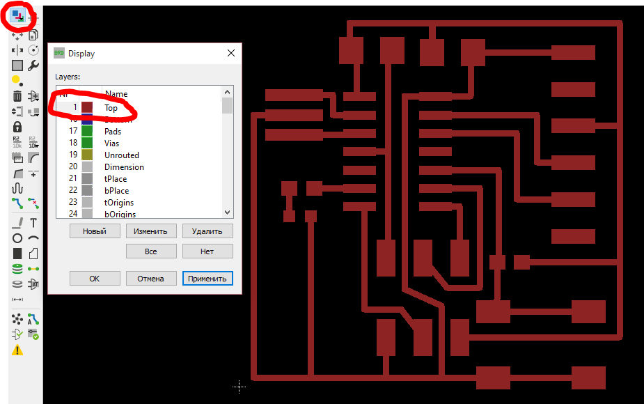
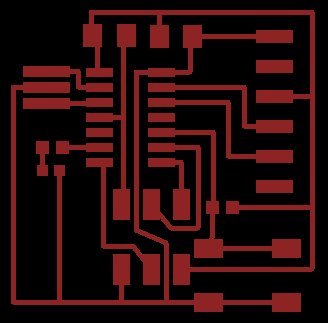
I couldn't use this image for laser engraving so before export process I opened list of layers and choose only "Top"-layer. Result became better: We used Trotec laser and engrave plate 5 times with maximum power and 20% of speed to remove top (cuprum) layer. The result looks like this:
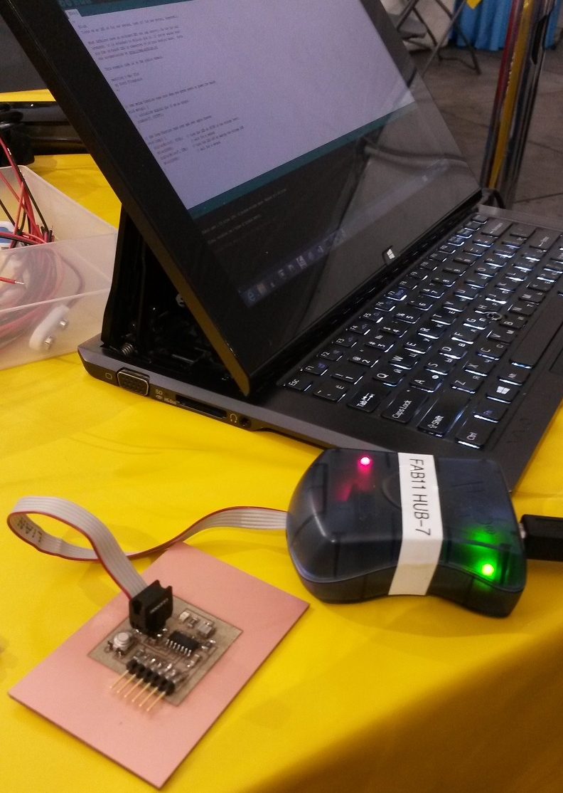
After soldering of the components we used AVR programmer to connect and run our board:
Shield
Because I failed to make a board designed in DipTrace (because I haven't proper tools) so I decided to make less precise board and had designed it in Eagle.
Further text were taken from electronics page:
I decided to make my homework corresponds to the final project (smart wardrobe). I chose Intel Galileo as the base platform for the electronic part because it can be easily connected to the Internet through Ethernet network. On Galileo platform microcontroller (processor) soldered to the circuit so I decided to make a great shield with connection to RFID sensor and engine (which will open and close wardrobe).
To test all things together I used breadboard:
I downloaded Eagle files of proto shield for Arduino from the official site and redesigned it. Firstly I deleted all unuseful things (to delete several items in the same time - define a group, choose delete tool and press Ctrl+Right Click on the group). I saved pins near the edges of the circuit board - the needed to insert shield to Galileo.
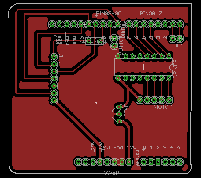
For motor driver I used ULN-UDN library, for voltage stabilizer - SM-Eagle library (Galileo 12V to 5V for the stepper motor). I took into account sensor (RFID module), motor driver, stabilizer and networking communication so final result looks like this:
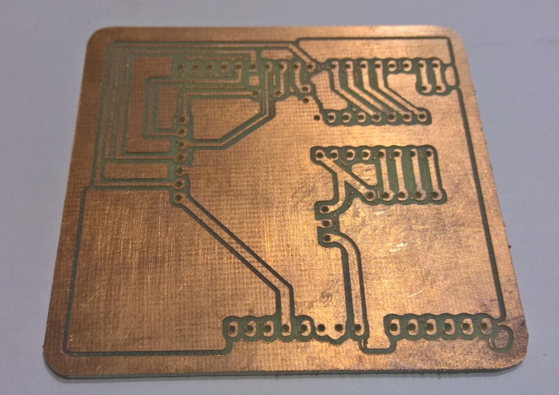
Before cutting I checked designing rules in Eagle and found that my 0 Ohm resistor is too small so I decided to use wire to connect to electric routes. Board were cutted on FlexiCAM S2 150250:
After the soldering I tested almost every connection with tester and it saved me several hours later to debug my project. How it works:
I reserved two pins 0 and 1 for connection with other controllers. I used Arduino Leonardo 10 and 11 pins to connect and send commands to Galileo RX/TX pins: 1 - open wardrobe, 0 - close wardrobe.