
Final Project
Quick Links
The Big Idea
Sensor and control network
Creating a UI
Making a heating element
Making a BrewBox
Evaluation
Download Files
To integrate the processes learned throughout the course into one final project.
The Big Idea
My final project idea was to make an automated beer brewing system for the home. I stuck with the frontrunner from week 1 all the way through the course because I think it can be a great project and will hopefully benefit by being developed and used throughout the Fab Lab network. To disseminate the project all files will be open source and licensed through MIT.
It became clear to me after much research into the process of making the perfect pint that I needed to concentrate on one part of the process - the fermentation stage. There were 2 main reasons for this :
1. I would never have finished a bigger system by the end of the course
2. The "full" brewing system needed to reach boiling point for a large volume of liquid and would therefore need to be very high power (or gas) and I wasn't confident I could work safely with either.
After identifying the fermentation stage as my focus I set myself some goals for the electronic system.
I needed the electronic system to measure two things. Did the beer need warming up? (to ensure the yeast has the perfect environment to make lovely ale) and is it ready to drink yet?( has fermentation finished yet). For a detailed view of the processes and systems planned and used in this project see week 16.
Sensing
Beer Temperature
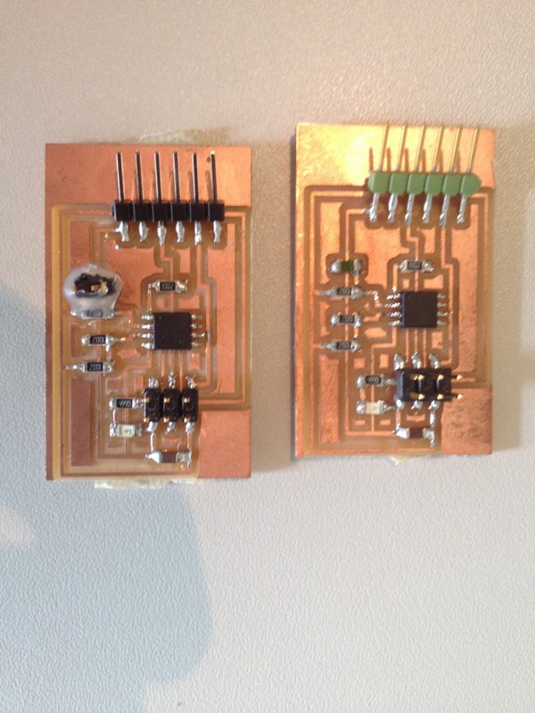
To sense the temperature I initially modified my thermistor circuit from input week to make it capable of receiving instructions and found that it worked well for the range of temperatures I needed to sense (20-30 deg C). Using the lessons learned in PCB design and milling I re-designed my thermistor board to use the ISP header for serial MOSI/MISO communication. I incorportated this type of communication (transmit & receive) on every board in the network. Another method used with all the boards I designed and made was to where possible, use indicator LED's on any spare output pins to show that the board is sending & receiving data. This is a common method used for fault finding on boards. If you can identify that a chip is sending & receiving messages then it quickly narrows down the area of possible error.
To program the beerTemp board I modified the C code for the original thermistor hello world board. The main modification was to set up the receive and transmit comms (instead of the previous program which asked the thermistor board to simply keep throwing out temperature readings every clock cycle. It was important for me to change this method due to the fact that I was making a common serial network bus that all circuits would listen and talk on, and possibly at the same time. Using the analogy of a multiway phone call, it is only possibe to understand what someone is saying if you can hear them clearly, they are talking a language you understand and they are talking at a speed that you can listen to and comprehend each word. This is exactly the case with programming a network and in a serial network with a common bus of daisy-chained modules each module must be identifiable by the DMP (decision -making-processor). To do that each board is assigned a command to listen for and that command will only identify one function on that specific board. For example the beerTemp board C file was modified to listen for a '1', and when it read a '1' on the serial input it completed the voltage comparison across the thermistor and saved the value in the ADC (analogue to digital converter) as a 10-bit (2-byte) number. As the reading was stored as a 2 byte number the values were stored in ADCL (ADC-Low) and (ADC-High). Next the serial output pin was configured and the 2 byte message was sent back to the DMP, which in this case was my laptop runnin a processing script. This can be seen below:
// main loop
//
while (1) {
//
get_char(&serial_pins, serial_pin_in, &chr); // get char from serial
//if(pin_test(led_port,led_pin)){clear(led_port,led_pin);}else{set(led_port,led_pin);};
if (chr == '1') { //if '1'
set(led_port,led_pin); //
//
// initiate conversion
//
ADCSRA |= (1 << ADSC);
//
// wait for completion
//
while (ADCSRA & (1 << ADSC))
;
//
// send result
//
chr = ADCL; // store ADC-low
output(serial_direction, serial_pin_out); // make serial pin an output
put_char(&serial_port, serial_pin_out, chr); // send out ADCL
char_delay(); //wait
chr = ADCH; //store ADC-high
put_char(&serial_port, serial_pin_out, chr); // send out
char_delay(); // delay
input(serial_direction, serial_pin_out); // make serial pin input
clear(led_port,led_pin); //switch off the LED
}
}
}
To send commands and interpret the responses a processing script was written to output a UI on the laptop screen and conduct the transmit/receive comms throughout the network. The part which dealt specifically with the beerTemp can be seen below:
myPort.write('1'); // send request for beerTemp
delay(10);
if ( myPort.available() > 0) { // If data is available,
low = myPort.read(); // read it and store it in val
}
if ( myPort.available() > 0) { // If data is available,
high = myPort.read(); // read it and store it in val
}
delay(50);
value = (256*high) + low;
//println(value);
beerTemp = calcTemp (value); // use function calcTemp to return a value for beerTemp
//println ("beerTemp "+beerTemp);
println("beerTemp = "+beerTemp+" padTemp = "+padTemp+" heater = "+heater+" overheat = "+overHeat);
The function calcTemp is used for both Thermistor circuits and this can be seen below: A fuction was defined and used as it was needed for 2 seperate boards, if only 1 board was used the function would have been left in teh main part of the code and just put in at the right sequential order.
float calcTemp (int val){ // Maths function taken from Neil's python program - turns voltage comparison on thermistor circuit into degrees C
if (val > 511){
val -=1024;}
V = 2.5 - val*5.0/(20.0*512.0); // works out voltage
R = 10000.0/(5.0/V-1.0); // works out resistance
// println("V "+V+" R "+R); // print the result in console to check results
float T = 1.0/(log(R/R25)/B+(1/(25.0+273.15))) - 273.15; //calculates & converts to temperature (deg c)
return T;
}
Pad Temperature
To be able to contorol the temperature of the beer I needed to have a method of heating the environment up to a user defined temperature within a small range - 22degC-25degC. To do this I decided to try and make my own heating element that could be encased in a thermal insulator, powered from a DC supply mains source and switched on/off using PWM (pulse-width-modulation) from a 5v logic board to get to different temperatures. See next section for more details. After making the pad and thinking about the thermal dynamics of the system it was necessay to have a 2nd tempeature sensor that would plot the padTemp vs the beerTemp and allow for a thermal cutout to be programmed. The thermal cutout is important for 2 reasons:
1. If the beer in the bottom of the tank was in contact with a heating pad above 40 degC for a substantial amount of time the beer would spoil and the yeast would die.
2. For safety reasons having a thermal cutout (similar to an electrical fuse) will ensure that the element will stop heating before any possible fire risk would occur.
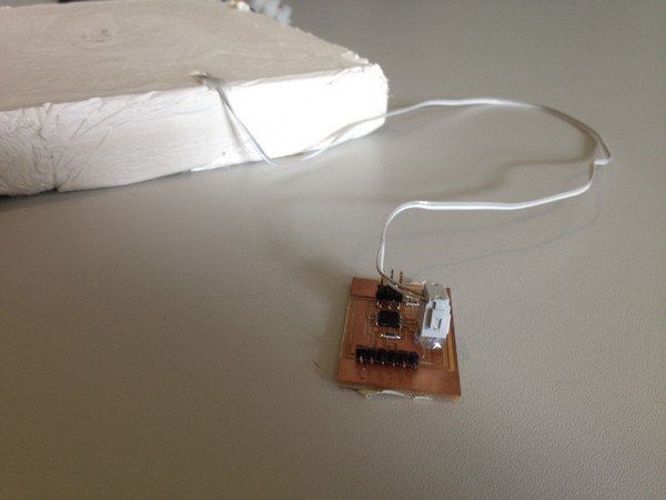
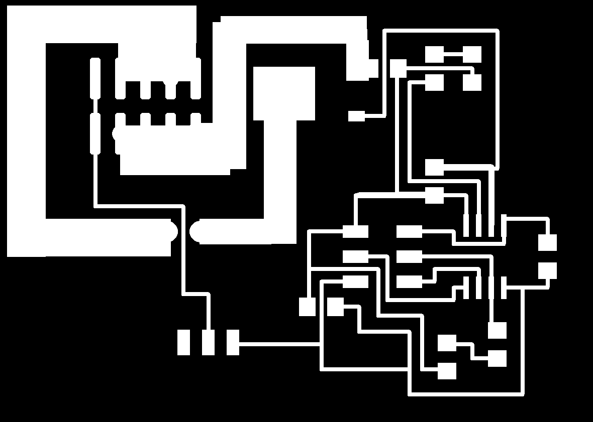
To produce the padTemp board I made exactly the same board as beerTemp with the minor adjustment of attaching the thermistor to the board using a IDC connector and some ribbon wire and encasing the thermistor in the plaster mass of the heating pad.
![]()
To program the padTemp board I used the same modified c code as with beerTemp but changed the listening command to '2'. The only other difference in the C code was the change in MUX values. Looking at the Attiny 45 data sheet you will find that the MUX values are a changable 4 digit binary number which sets the mode for the ADC. For beer Temp I used the MUX values 0111 which gave me a 20X gain on PB4-PB3. This works out nicely for the range of 20-29 degrees at which the converstion tops out. With the pad temp I had done some testing and knew the pad could get up to 56 degC (although I planned an inital cutoutTemp of 38. This gave me an issue withe my range and meant I needed to get rid of the 20X gain. This was done by changing the MUX values to 0110 as detailed in the data sheet. I spent quite some time trying to get the new maths to work and eventually (after modifying the processing script to account fo the loss of gain) I was able to get something sensible out. When left with the previous processing script I was getting a reading of NaN for my T value. This was very hard to debugg but eventually with some help and advce from Joel I was able to change the post-processing maths to not treat the number as bi-polar but simply a Vvalue and this seemed to work perfectly well,
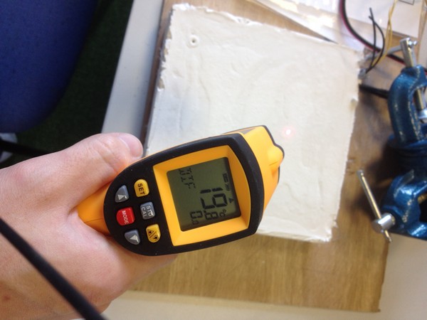
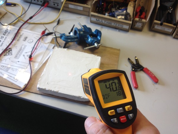
After all the debugging in the processing script it became evident that I did not need to go through all of those changes and in actual fact my overHeat padTemp value should be in the range of 20-30 deg c. Why? I hear you ask. Well the embedded thermistor was positioned in a set location so to not come in to contact with the NiChrome wire. This positioning choice did mean that whilst heating up I was getting a differential of approx 10 degC between the hotsots of the heating element and my measured thermistor temperature. Dam! all that work for nothing. I used an infra-red thermometer to calibrate the temperature difference and that will be a goof enough start but it also became clear that the pad would act differently as it cooled than when it heated up which would mean a non linear conversion between padTemp and actual Pad Temp. At this stage I can only make some assumptions, test it, and program to work in theory from what I have witnessed/recorded. There will need to be a period of testing and recording of temperature values to help program a robust system for keeping a consistent temperature in the brew.This can be done by running a processing script which will output all read values to a excel spreadsheet.
See downloadable files for changes to processing script and example recording program.
To measure when fermentation has stopped I had a couple of different options:
Specific Gravity sensor - This is the most well known and accurate way of measuring alcohol content and therefore with comaritive readings it s possible to measure when the fermentation process has finished. However after a fair amount of internet research it seems that electronic specific gravity is not a trivial measurement to take and that being the case sensing systems cost upwards of £1500. The problem with making a sensor is that error is easily introduced into the measurement with the inclusion of bubbles in the sample. There is a kickstarter project to make a cheaper electronic specific gravity sensor, but it will still cost >£500 and it is not know if this project will be a success.
Co2 sensor - When yeast is fermenting the beer it releases Co2, therefore If i could plot the rise of Co2 and recognise when it was no longer rising then I would be able to conclude that fermentation has ceased. However this system would require a controlled valve pressure release system to reset the counter of co2 levels, also I found it difficult to get my hand on a co2 sensor and they were reasonably expensive.
Pressure sensor - As Co2 is produced within the brewing tank, it will increase the pressure and therefore (similarly to the system above) I could plot the pressure level and when pressure no longer rises above a certain level the fermentation process should have finished. This system has the benefit of using a pressure sensor which is much cheaper than a Co2 sensor but it would also require a controlled valve release to work. I initially thought that using a traditional airlock system could work with this but that was proved wrong as when pressure is released in an airlock it remains constant within the brew tank.
Conclusion
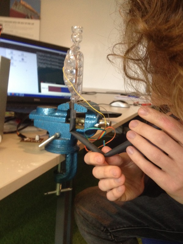
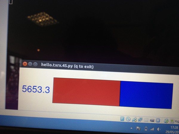
None of the options have an easily incorporated system for my project. After thinking some more about how to plot the fermentation I decided to try the step response circuit from input week. In the lecture this circuit was shown to be very versatile and I hoped it could be used to plot the change in water level in a normal airlock as a bubble passes through.
I milled and stuffed the circuit board and then tested it by blowing a bubble through an Airlock and looking at the response of the python program.
Success, I got a raise of approx 1000 from the base rate of 4500. That is definitely a clearly definiable difference that should be above the amount of noise caused in the reading when people move around the device and switch on other mains powered equipment. Currently the processing script to map the step response is still being written but it will use the same format of call-out and response that each PCB uses on the network.
Control
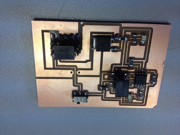
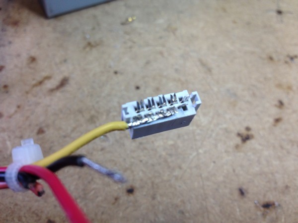
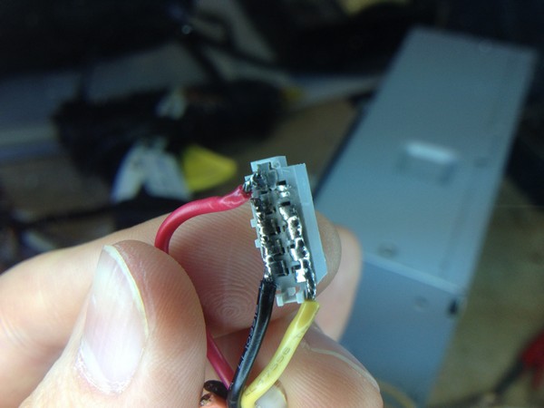
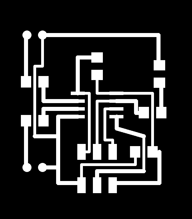
To power my heating pad I needed to be able to switch mains powered DC electronics using a 5v signal. This was achieved using a 16a 50v rated MOSFET that takes a 5v signal. A FET stands for a Field effect transister, MOS for Metal oxide semionductor. I understood the function of a transistor but had not come across a MOSFET before. I did thnk that I'd need to power the heating element using a relay, so why a MOSFET?
MOSFET's are only usable with DC not AC power. They are cheaper, smaller and use less energy as it doesnt contain moving parts (exluding the field effected gate). When designing and making the board I did need to be aware of seperating the power and logic circuits. It was necessary to make my tracks much larger for the 12v 3a supply and I actually spread the load over 4 pins each of a 2 X 5 connector (shown below) this worked nicely and allowed me to use some stock logic level connectors for the power part of the circuit. This connector from the PC supply also allowed me to output 5v to use at a later date when I am no longer powering from a PC. I added a slide switch into my circuit design to disconnect that 5v until I want to use it. The connector was covered in insulating hot glue to protect the contacts.
To control the MOSFET using programming was very straight forward. I used the arduino IDE to program the board to listen for a '3' send the pin high, and that pin was connected to the signal of the mosfet via a 1M ohm resitor to ground. The reason for the 1mohm resistor is that the MOSFET actually needs very little voltage to be swicthed on. I was happily suprised how easy it was t control. It had now been worked out that with testing I would no longer need to use PWM. The reason is the heating element was only going to heat the brew gently when full power was applied 100% of the time and with the programming script I had written it should maintain temperature well. If after more testng I decide that the heating element should be on in 80/20 cycles I could still program that from a non-PWM pin as long as the tiem period for each cycle was more than 30 seconds (which it would be).
That being the case I wrote this program to control the mosfet circuit.
#include <SoftwareSerial.h>
SoftwareSerial mySerial(0,1); // RX, TX
int heater = 3;
int txLed = 4;
int rxled = 2;
char tempChar;
char inputChar; //variable to store the incoming byte
void setup()
{
mySerial.begin(9600); //start serial comms at 9600 baud
pinMode(heater,OUTPUT); //set LED pin to output
pinMode(txLed,OUTPUT);
pinMode(rxLed,OUTPUT);
digitalWrite(heater,LOW); //turn LED off to start with
digitalWrite (rxLed, LOW); //turn LED off to start with
digitalWrite (txLed, HIGH);//turn LED off to start with
pinMode(1,INPUT_PULLUP); //make pin1 an input to start with
}
void loop()
{
if (mySerial.available()){ //check if there's an incoming byte waiting
inputChar = (mySerial.read()); //if so, store that byte in inputChar
switch (inputChar)
{
case '1':
tempChar = (mySerial.read()); // read serial and ignore
tempChar = (mySerial.read()); // read serial and ignore
break; // get response from temp board 1
case '2':
tempChar = (mySerial.read()); // read serial and ignore
tempChar = (mySerial.read()); // read serial and ignore
break; // get response from temp board 2
case '3':
//digitalWrite(power,HIGH);
break;
case '4':
//digitalWrite(pow,LOW);
break;
case '5':
//digitalWrite(beerReady,HIGH);
break;
case '6':
//digitalWrite(beerReady,LOW);
break;
case '7':
digitalWrite(heater,HIGH); // light Heater inicator LED
digitalWrite (rxLed, HIGH); // light receive inicator LED
digitalWrite (txLed, LOW); // turn off Transmit indicator LED - FLASH
break; // switch heater on (mosfet board)
case '8':
digitalWrite(heater,LOW); // turn off heater indicator LED
digitalWrite (rxLed, LOW); // turn off recieve indicator LED
digitalWrite (txLed, HIGH); // turn on transmit indicator LED
break; // switch heater off (mosfet board)
case '9':
break; // read step response
default:
break;
}
}
}
Important features of this program
pinMode(1,INPUT_PULLUP); //make pin1 an input to start with
This was very important to get the comms to work correctly. It made what would later be turned to an output pin an input until it was needed to send out information. This helped control the communication in the network and keep teh pin clear until it was needed.
switch (inputChar)
The switch statement allowed me to write the program that would address all boards (initailly) and it works really nicely by replacing a load of "if" statements. The case which follows will only be executed if the right command is sent out from DMP and listened to by the board. If the board hears a '5' and is waiting for a '2' or '3' the it simply reads it says its not for me and ignores it. This is a great way of building up a modular network, by writing extra case statements when new boards are added, but having a network where mutiple boards are listening to inputs and giving an output can get messy and needs some order.
tempChar = (mySerial.read()); // read serial and ignore
This command restores order and ensures if another board is asked for an outout( ie a board that isn't me) and it is expected to send a response, the next 2 bytes of information sent down the network should simply be acknowledged but ignored. This is important because as talked about earlier the message sent out by a temp sensor board is made up of a low value and a high value. Taken in isolation the high value may be a trigger for another part of the network and therefore needs to be read but ignored, rather than read and possibly acted on.
Powering the heating element
I was very happy to find out that I could get enough power form a DC switching power supply to heat the wire of my heating pad. I initally tested some 0.6mm NiChrome wire to try and produce a 2W heating element (in line with those brew-belts) used for the same application.
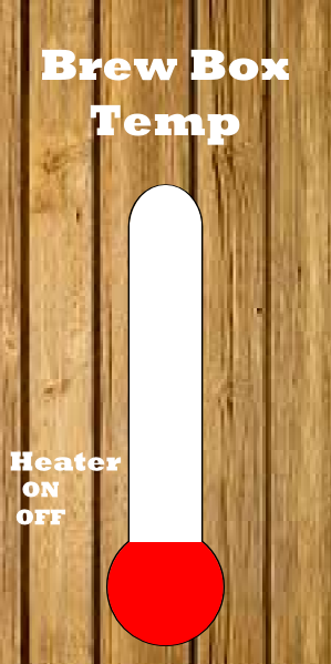
Controlling the system from Processing
The processing script that I wrote and developed also has some important concepts embedded in the code. The first is known as the Schmitt trigger effect. This idea is the concept of switching on and off at slighty different levels to take account for the noise in the signal. If I were to choose to turn on the heater at <24degC and switch off at >24degC there will be a point at which the temperature goes back and forth over the switching line many thousands of times. If i were using a relay (moving parts) the this switching action can be very damaging to the circuitry and its components. It is therefore much better to say that I will swicth on the heater when the beerTemp is <23.5degC but only switch off at =>24.5degC, that way allowing for slightly noisy readings to not kill my circuitry.
Another safety feature written into my processing is overHeat mode. It was important to write in an extra condition which controls whether the heater is switched on or not, again taking account of the schmitt trigger effect. Looking at the code below you can see that overHeat is swicthed on if padTemp>29.5 and once on the padTemp must drop below 28 degrees before being switched back on.
A simple concept but an important one in my processing code is the condition to only perform a funtion if it will change the state of something. What I mean by that is the heater is only switched on when all conditions are met in the if statement and one of the conditions is that the heater is off. Without the inclusion of this condition the statement would continue to be true for a long time and every clock cycle the program would continue to try and swicth on something that is already on. Using the boolean variable heater and overHeat it was possible to control the flow of instructons and take them down to a point where functions will only be initialised when they will change the state of a board.
if((padTemp < 29) && (beerTemp < 24) && (overHeat == false) && (heater==false)) //if tempHeight is less than threshold and heater is false (off)
{
heater = true; // make heater true (switch on)
println("switch heater on"); // print "switch heater on" in console
myPort.write('3'); // turn indicator light on
delay(50); // necessary to delay 50ms in between messages transmitted to a board
myPort.write('7'); // turn heater on
heaterIndicatorY = 442; // moves UI heater indicator to on (on screen)
}
if(((padTemp > 29.5) | (beerTemp > 25)) & (heater==true)) // if tempHeight is bigger or equal to threshold and heater is on
{
heater = false; //turn heater off
println("switch heater off"); //print "switch heater off" in console
myPort.write('4'); // turn inicator LED off
delay(50); // necessary to delay 50ms in between messages transmitted to a board
myPort.write('8'); //Fr off on serial port
heaterIndicatorY = 467; // moves UI heater indicator to off (on screen)
}
if((padTemp > 28) & (overHeat == false) & (heater == true)){
overHeat=true;
}
else if ((padTemp < 28) & (overHeat ==true) & (heater == false)){
overHeat=false;
}
Making a heating element
As I understand it, creating an efficient heating element is a balance of power, surface area and the right thermal insulating material to act as a storage heater. NiChrome wire (an alloy of Nickel and Chromium) is industry standard heating element wire and is used for its robustness at high temperatures and low resistance.
To work out how much wire I needed I did some simple calculations and then measured the resistance of the wire using a multi-meter.
For the test
P=VI
25 =12I
I = 2.08amps
V=IR
12=2.08R
R= 6 ohms (approx)
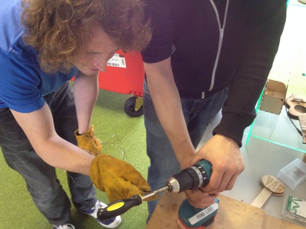
I cut the amount of wire needed and then wound it into a spring using a screwdriver and an electric drill. The reason for winding a spring was to make the distribution of wire easier to control.
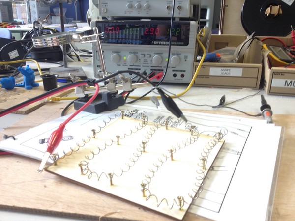
After winding a spring I powered it using the lab desktop power supply to see how it would react.
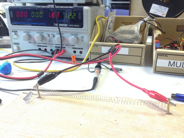
The wire heated mildly but there was some concern from my colleague that the wire may burn out, and I was concerned that it didn't have enough umphh to heat 25 litres of liquid. Taking both points on board I decided to increase the gage of wire to 0.9mm and aim for 36 watts. following through the same procedure I found that I wanted 4 ohms of resistance with 3 amps from my 12v supply.
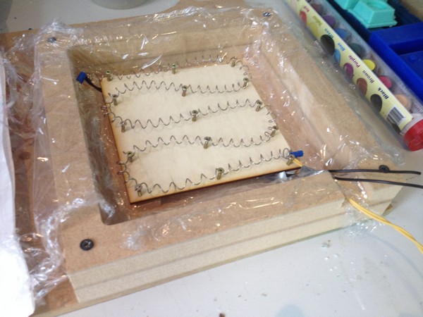
This time after winiding a spring and stretching it out I needed to create a template for my spring to attach to, to keep it's shape, and spread the wire evenly over the surface. It is important at this stage to not snag the wire, as all snags will be natural heat spots in the element. I designed the template to be a 150mm square plywood piece with 3 rows and 5 columns of equally spaced pilot holes (2mm) to attach screws to and wind my wire around. This worked very well and after leaving the wire to heat for over an hour I was very happy with the heat supplied and the robstness of the element.
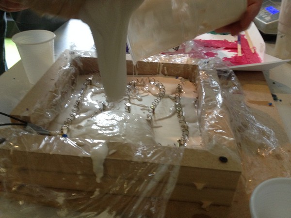
Next I needed to cast the element in cystacast plaster. To do this I designed a mould in Solidworks and cut out 2 pieces of wood on the shopbot and screwed togtheer to make the mould. I then lined the mould with cling-film to give it a chance of releasing from the MDF, mixed the plaster (approx 1.5 litres at a 3:1 ratio, plaster:water). After doing 2 batches accurately in a pint glass using scales I found that I was happy enough to mix by eye and judge the consistancy of the mix. When casting the mould with the embedded heating element with crimped wires attached I took extra care to keep the element out of direct contact with the plywood, I also aimed to have the element much closer to the top than the bottom and in the end got about 2mm of coverage over the element, which I was very happy with. The mould was left over night (as it was the end of the day a when it came to release the next day it came away quite easy. I was concious of using to much force on the plaster and so I actually broke the mdf frame to be on the safe side but in hindsight this wasnt necessary.
Creating a UI
See week 15 for my initial work using Processing
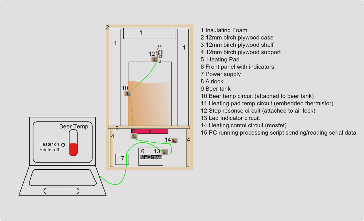
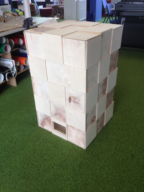
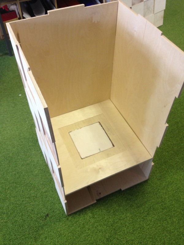
A big part of the MiBrew system relies on creating an insulated, heatable environment for fermentation, and so for this I designed a brewbox.
I struggled for inspiration initally when thinking about the aesthetic and concentrated on the functionality needed.
- Stable
- Hold the beer within it
- Have a space for the heating pad
- House the electronics
- Have room for supplimentary insulation foam
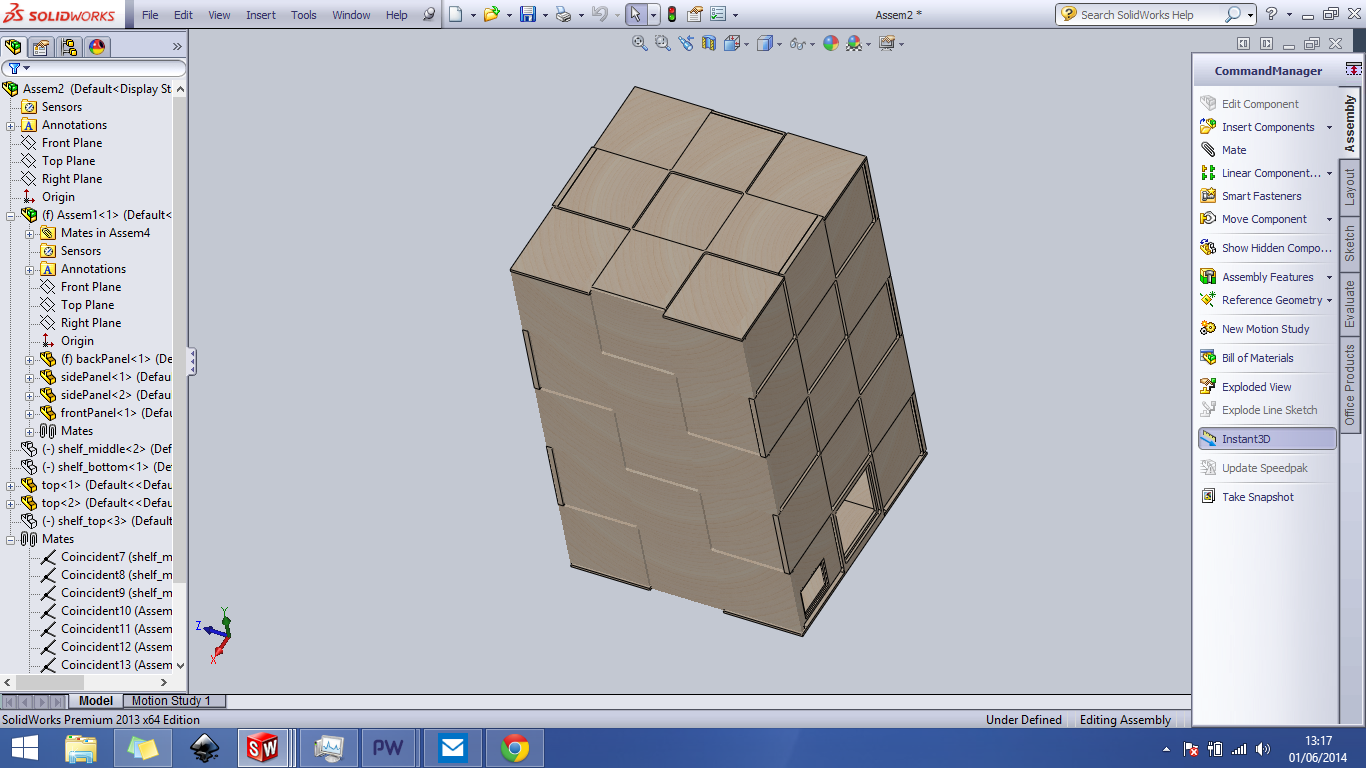
I designed the box with the shopbot in mind, knowing the type of finger joint I wanted to use and the sheet size available. I have used Solidworks for a few years now and find it invaluable when it comes to iterative design. I simply wouldnt use anthing else it has everything any designer needs and plenty of extra funtionality for the odd speciality assignment. See week 2 for my review of Solidowrks and some other CAD packages.
Knowing the machining process and having the functionaliy at the front of my mind was leading me to create a big box. An important part of any product is that it's appealing and suits it's envirmonment. MiBrew is going to live in your living room/kitchen/dinner and so it had to look good. Struggling for ideas I was coming into the lab by train and i noticed an interesting building in manchester which is square and pretty dull in shape but had a funky checkerboard paint pattern.
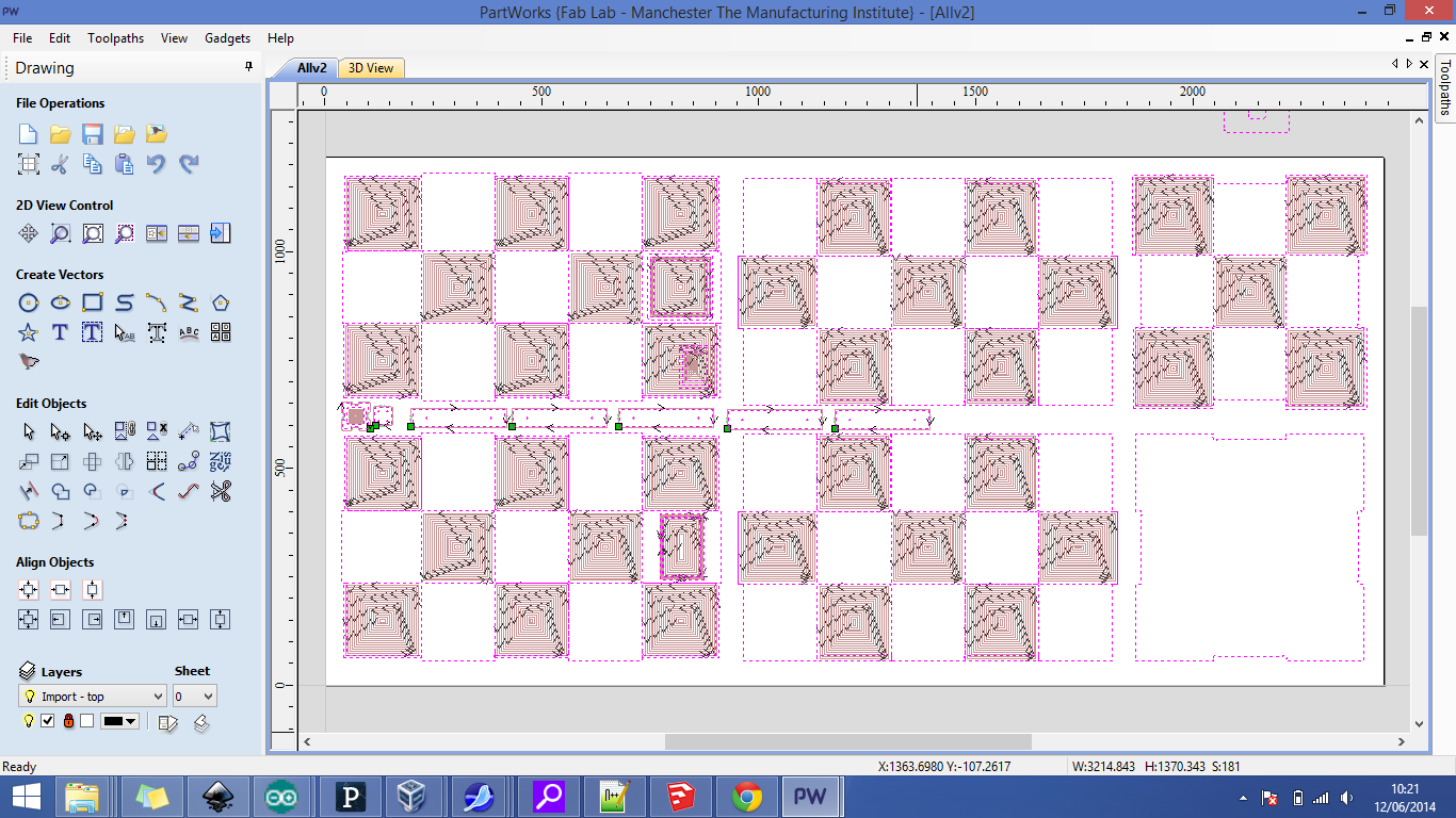
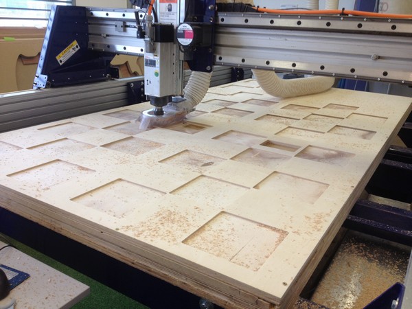
That was it, I had an idea and had to go with it so I went about editing the design in solidworks, exported to pdf and set out toolpaths in partworks. I spent a lot of time figring out what would happen when a positive hits a negative square and how it would work when nothing can be truely square using a cnc milling machine (fact of the day:end mills are round!) but I think it was worth the time.
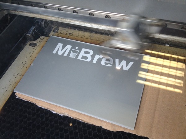
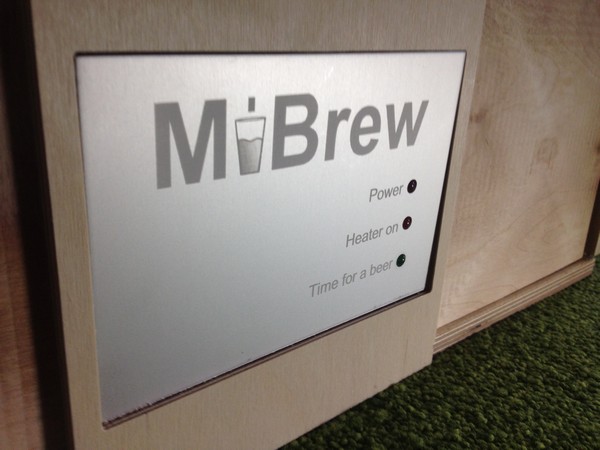
Designed as a logo in CAD week, I sourced some anodised aluminium and engraved a panel with the MiBrew logo and LED indicator labels.
Settings: Speed 80 Power: 35 (RASTER ONLY)
Evaluation - Does it work?
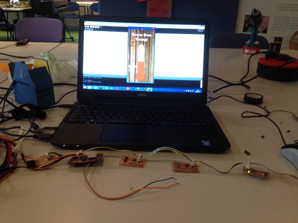
I have not been able to test out the fermentation side of the MiBrew system just yet but as far as the sensing and control network goes, it works. For the local presentations I did a live demo in which we heated about 250ml of water above and below the threshold at which points the heating element switched on and off accordingly with the inicator lights illutrating tthe system. There is still alot of testing to do and calibration on the heating and cooling points to try and maintain a steady brew temperature.
Am I happy with it? What did I get out of it?
At this point I am very happy with what I have achieved and I am excited about improving and developing the system further. This project obviously has a functional output - beer! but worth more than that to me is the electronics and programming start that I have now to build upon and develop further. It has always been an area that I could imporve and I think that the MiBrew project gives me the reason to keep practicing and progress my knowledge.
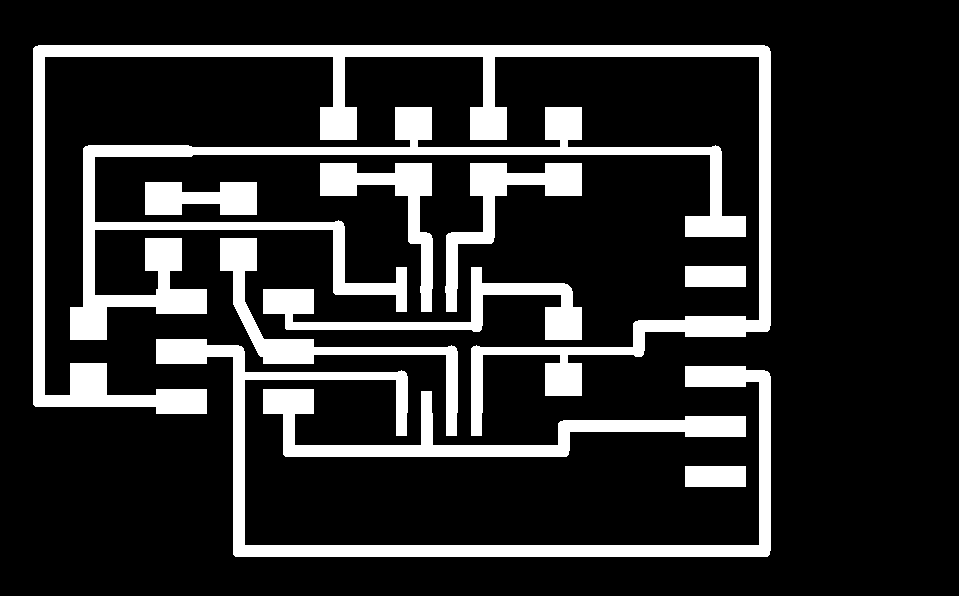
Circuit/Modella Files
beerTemp/padTemp - traces - interior
mosfet (heating element) - traces - interior
LED indicator - traces - interior
stepResponse - traces - interior
Shopbot files
heating element mould - crv - vector
brewbox - crv1 - crv2 - vector1 - vector2
Laser Files
heating element template - vector
Aluminium panel logo - vector - svg
Programming Files
tempRequest - .c
tempRequestHighRange - .c
Mosfet board -.ino
LED Indicator - .ino
Processing Script - .pde - UIbackground.png
