Week 15 - interface and application programming
Brief
To program a UI (user interface) to sense an input or control an output.
Intro
For this weeks assignment I was keen to try and use a process needed in my final project, and as such I chose to try and drive a UI with my temperature sensor circuit. In my final project one of the goals is to sense and regulate the temperature of the beer throughout the fermentation process and so this will be an integral part of the whole system.
Initially I concentrated on making a UI using Processing. Processing is a coding language that allows graphical output to be driven from input and output devices. It is closely linked with Arduino, and with a wealth of tutorials available online and an open source ethos to project creation it seems to be a very useful program.
As I understand it Processing predominantly outputs to software whereas Arduino predominantly outputs to hardware.
Processing
First of all I worked through some of the examples that are built in to the Processing program. They helped me understand some of the basic draw functions which can use colour and shape.
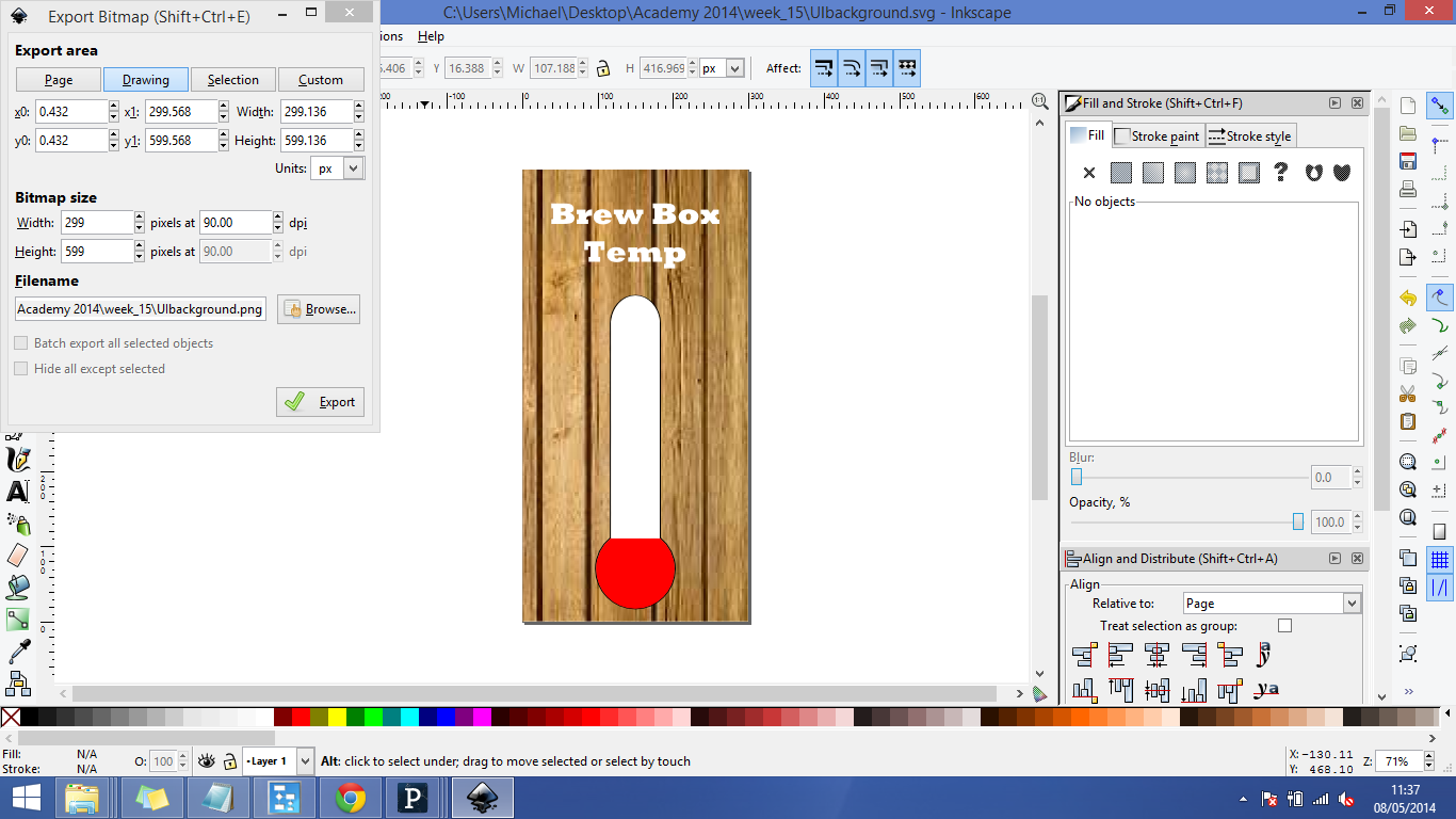
I then decided to create a background for my UI that would look good on screen and display the temperature by showing a thermometer. I used Inkscape to draw my background and took care to leave the area of the thermometer blank (to allow a drawn area in Processing).
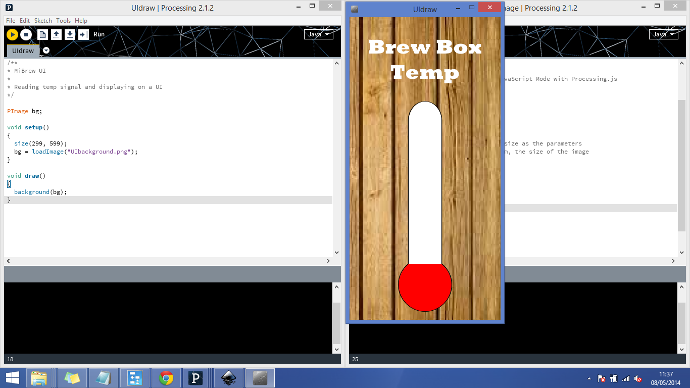
I then wrote a program to draw a red rectangle within the thermometer based on the position of the mouse within the window. I loaded my exported png to the window as a background and mapped the pixel position of the rectangle from my Inkscape file. I am only just beginning to use Processing and this week I got a lot of help from Joel to understand the structure of the code, syntax used and available functions.
Firstly I simply loaded my background, making sure the window size was exactly the same number of pixels as the exported png.
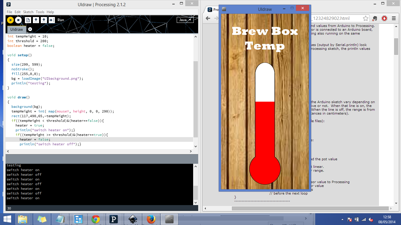
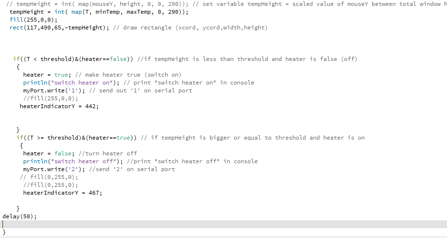
Next I added in the drawing of a red rectangle related to the mouse position within the window. I also added in a threshold variable which illustrates the temperature at which my fermenting beer should be kept at. When the value reaches the threshold level the program prints the line "switch heater off" in the console. This was achieved using an if statement. and the pixel height 200 as the threshold level. It was also important to add in the condition of only switching the heater on/off if it was currently in the other state. This stops the program sending an instruction to switch on repeatedly and then off repeatedly. As I understand it this would be bad because when a chip is sending data it can't be listening for data so it is important to understand the flow of comm's in a network and to think about which parts talk and which parts listen.
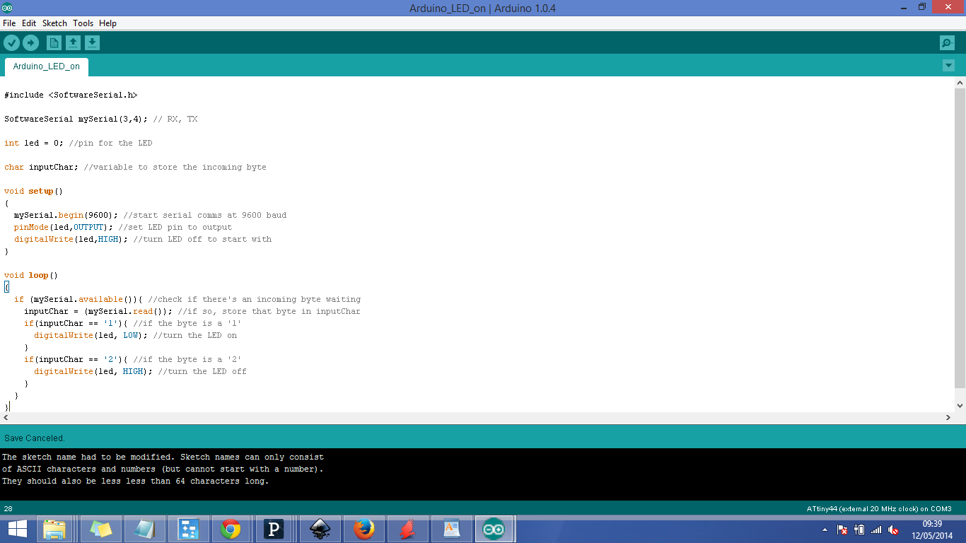
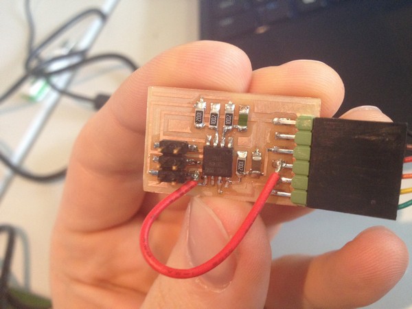
Next I wanted to connect the program to an output board to simulate my relay circuit in my final project. I decided to just use my bridge circuit from the network comm's week as it has serial communication and an LED indicator light to simulate the switch.
To use the circuit I created I had to re-program the bridge to listen for a '1' to switch on the LED and wait for a '2' to switch off the LED.
I then set up serial in my Processing program by using the import serial library instruction and using myPort.write to instruct the program to send a '1' on the serial when below threshold temp and a '2' when above threshold temp, thus turning the LED on & off. In doing this I realised it was important to set the baudrate correctly (9600) and to set communication on the right COM port. This can be done by getting the console to list all available COM ports at the start of the program. If more than one COM is available you can unplug a cable and re-check available COM ports to correctly identify the right port to send communication down. This port is then referenced inside the [] in this case it was [0] which says use the first COM port in the list (in programming numbers start at 0 and not 1).
Next I wanted to set up my UI to read the temperature from my thermistor circuit (from input devices week). In order to do this I had to make a modification to the circuit which connected up the Rx pin from the FTDI connector to the MOSI pin. This was necessary as the circuit was only set up to send information and not listen.
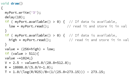
It was necessary for my program to send a signal to the thermistor board to ask for the temp reading and then listen to the response. Otherwise reading the serial data would simply show a string of byte's that are hard to interpret and convert to a meaningful temperature value. This was done by modifying the standard c program for the thermistor circuit to listen for a '3' then send out the low byte and then the high of the 10 bit temperature reading. I then used the maths conversion in Neil's program to translate the voltage drop across thermistor into degrees C, and included that in my Processing code.
I then changed my Processing code to map the rectangle in relation to T value between 2 new variables that define my temp range (minTemp & maxTemp) instead of mouseY position. The map function is a useful one in Processing and allows you to scale an output between 2 ranges. In this case I am scaling T between
(minTemp-maxTemp) and my available drawing area (0-290 pixels).
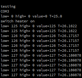
I wrote all the outputs to console before testing my circuit and found that helped in being able to see what data was coming in and going out. This is a good lesson going forward and Joel advised me this week to use LED indicator lights on each board I have if there is the space and if possible put send/receive indicators. This will allow me to debug knowing that the send receive functions are in fact working or not. This makes a lot of sense and should help in the inevitable fault finding as my network of circuits becomes more complicated.
I connected my thermistor circuit up and found that it was working nicely.
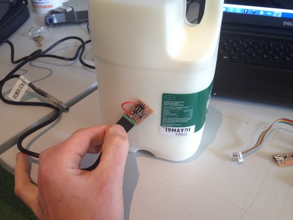
I then blew hot air on the thermistor and saw that it could reach about 30 deg c and used a bottle of milk from the fridge to cool the circuit down to 20 deg c. This gave me my temp range (minTemp and maxTemp values). I set the threshold temp to 28 degrees to simulate the switching of the relay and it worked well.
My final alteration to the UI used a heater on/off indicator sign which was drawn into my background. I then mapped the position of a drawn ellipse on my screen by introducing another variable heaterIndicatorY in Processing. This variable was then used in at the end of each if statement to change the y-position of the drawn ellipse dependant on the result of the if statement (is the heater on or off). I then played around with the fill values of the drawn ellipse to try and get it to switch from green in the 'on' position to red in the 'off' position but found I couldn't keep it that colour without affecting the colour of the drawn rectangle as well. I tried to use PShape to give attributes to each shape but found that made my ellipse invisible and so reverted back to simply switching the fill values between each draw cycle.
There is definitely more to learn and improve for my UI but for my first week using Processing I was very happy with my result.
Downloadable Files
Processing Script
UIbackground
tempRequest.45.c