
As described on week one assignment my initial proposal for my project would be to design and build a hybrid functional object between a large kaleidoscope and a outdoor binocular viewer recording the unique reflections and local information references such as the time, temperature, polution or uv radiation exposure status where its used as well to picture frame a moment like an unique fractal postcard.
Therefore that project intention was quite ambitious in the beggining regarding my lack of programing and electronics knowledge and background, so after some fabtutors advice reduced expectations to a more concentrated version of a pan and tilt camera project as proof of concept of what it could be from this first attemp onwards.
Final Project
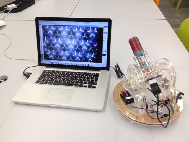
The project intention is to fabricate a pan and tilt camera structure automated to collect video images into a computer. Using most technological fabrication possibilities, knowledge and resources within any fablab.
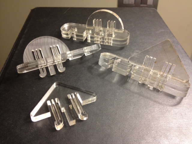
This example explored the detail and precision a laser cutter can achieve by creating custom sized transmition
gears as well as incased bearings. Inspired by the “MTM snap” press-fit construction, most all parts are connected
by similar system laser cutted from a 5mm clear acrylic sheet previously flat nested to reduce material waste.
Stepper motors actuate both axis and a web cam is inserted to collect the geometric kaleidoscopic images then
live viewed by a edited Processing code.
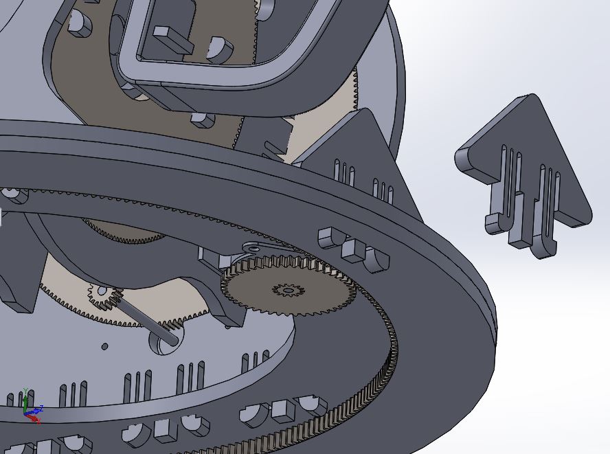
Since im more experienced on working with solidworks software due to my professional background, i've started to pick from the model made on "machine design week" to get fisically testing the important mechanical parts and assembly connections right into some lasercutted fab scrap materials like plywood and acrylic.
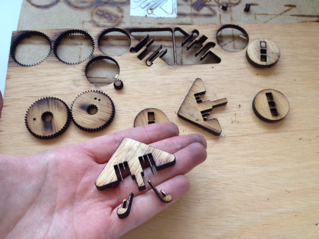
Cause most mechanical parts of the project relies on the world famous MTM snap system i've adapted its design principles here as well to reduce the fixtures (screws/bolts) to a minimum possible. MTM snap-fit system is always related to the material thickness and flexture properties. Here you can see the first results on plywood and acrylic.
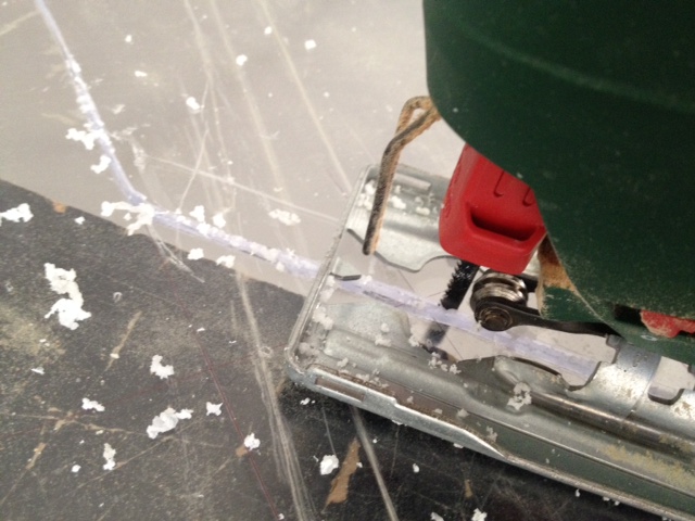
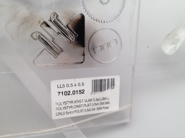
Went out to a general materials warehouse "AKI" to buy some acrylic sheets and then continue to laser cut larger structure parts. Only to figure out later that this, so called "acrylic" was not best suitable for cutting. Bad sign when the rotary speed of blade made material to melt and to burn black when lasercuted. Further notice: POLYSTYR IS NO GOOD!
Went out again this time to a specific store "Mundicril" that sell all acrylic stuff and cuts sheets on demand to get some acrilic good for laser cutting!
"PERSPEX is OK!" said the expert saleswoman :)
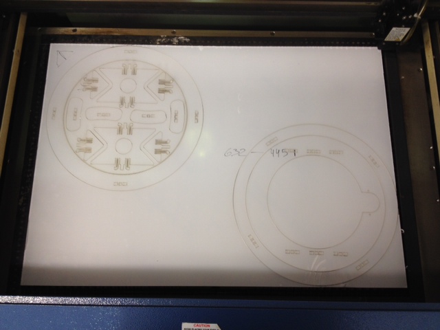
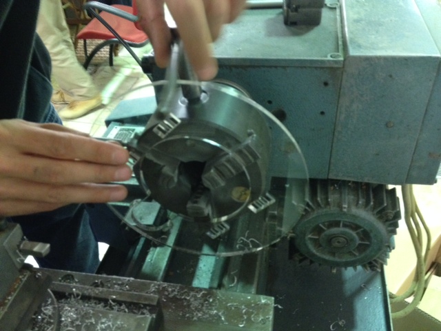
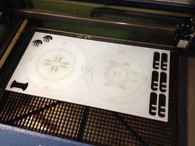
Back to fablab and started to lasercut some press-fit test parts on this new acrylic sheet. All confidant, since i've previously validated the snap-fit pieces and gear tightness went to lasercut the large base structural part. On Solidworks spent some time on laying flat nested all parts together to avaliable sheet and laser area avaliable and therefore avoid material waste and "money" disposal. This was the first nested cut nice and tidy:
Confidance that went down apart after this when realize they sold me acrylic 6mm thick instead of 5MM like demanded!?
It was a setback for all the week's hard work and struggle with project to move forward on the weekend...
NOTICE: ALWAYS CHECK MATERIAL SIZES AND THICKNESS BEFORE AND DURING PURCHASE!
After long thinking about pro and cons, and NOT having to redesign entire mechanical system to the thicker sheet, I decided not to give up and work with what I got available: found some good 5mm thick frosty sheet on fablabs acrylic scrap corner that could fit some laser cuts and make project go forward and not wait until next week start (monday) for buying some correct sized sheets.i took the base structure, previously cutted out from 6mm thick acrilic and adapted it to assemble parts and move on forward to take further overall conclusions.
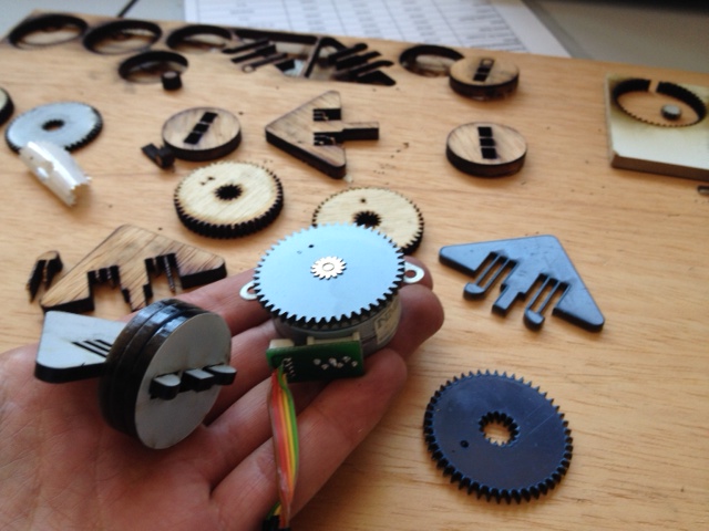
First motor plus gear and bearing concept fitting:
Cutted some upper parts out from 5mm frosty acrylic to then continue assembly parts and snap connections mechanical confirmation.
And it turned that some snap connections where too close and too many for proper fitting them without breaking.
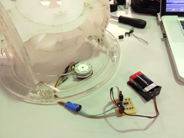
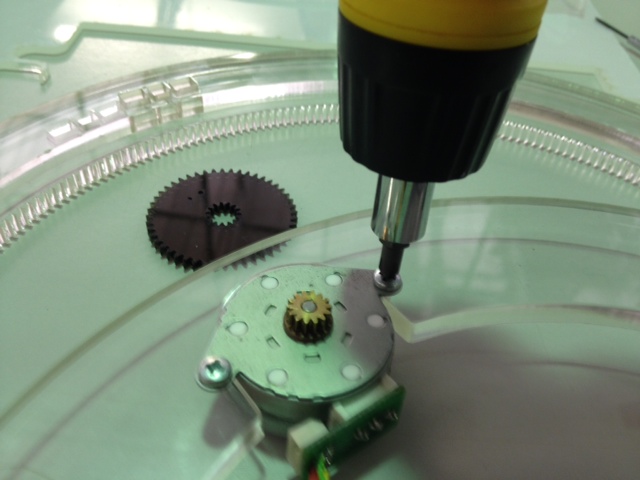
This first assembly test with the unipolar stepper running powered by a 9V battery (previously made on week12 for output devices assignment) was important to figuring out some design/mechanical flaws and improvements to be made such as removing black acrylic gear wheel (to get instead direct power transmition between small stepper gear and big acrylic gear) and scale down all scructure to reduce total weight:
That means back to the drawing board or should I say "solidworking" overnight? :)
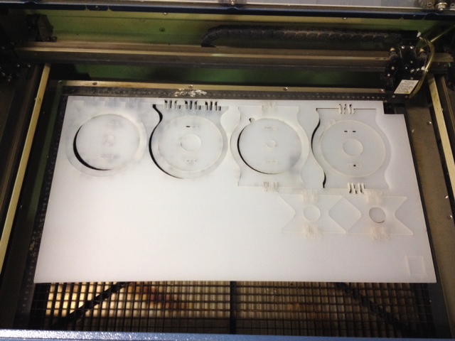
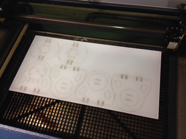
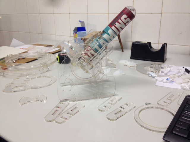
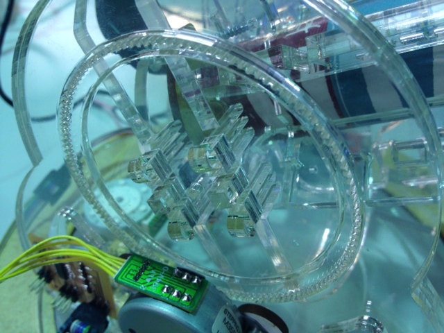
On this reviewed 3D design model, the objective was to reduze structural weight and size, as seen on this new flat nested laser cut template below, as well to adjust snap-fit tolerances and connections applying screws as a last resort. Once again first laser cutted some small snap-fit pieces to test before cutting all big parts:
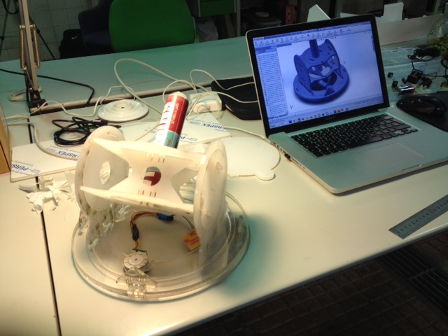
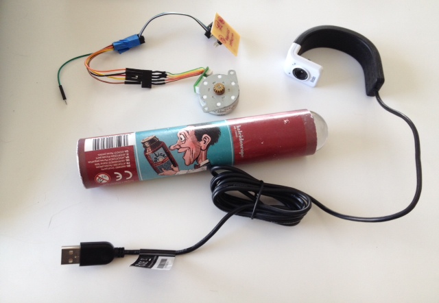
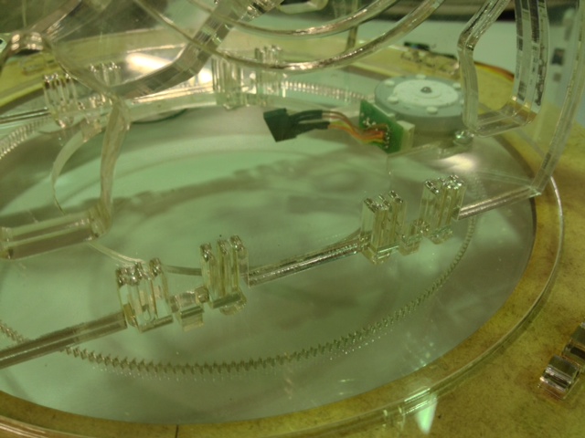
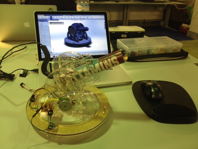
Components to integrate on mechanical structure: electronics PCBs, motors, webcam, and kaleidoscopic toy cylinder:
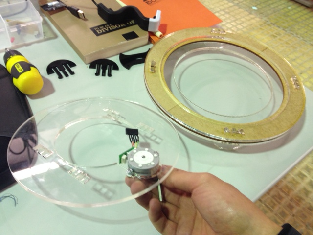
Here, at base bearing, decided to apply stepper gear wheel powering directly on acrylic large gear and therefore needed to add some mm height by a lasercutted mdf ring between acrylic external circles to improve as well the rotational movement.
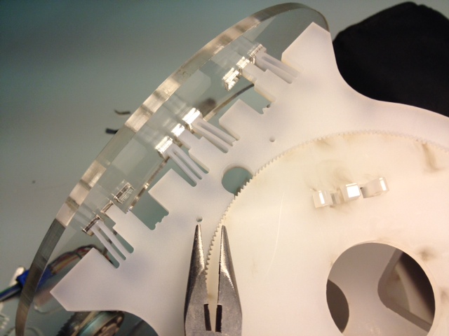
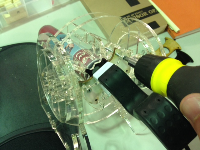
Below the webcam fitting with four M3x45 mm screws.
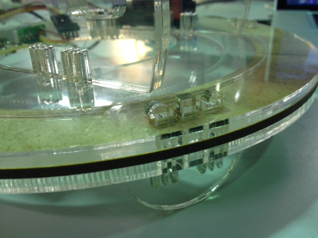
The "MTM snap fit" inspired connections ended up by resulting ok, as well as the incased acrylic bearing mechanism concept, although it can still be refined :)
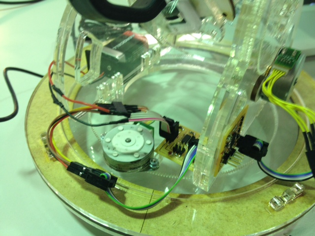
Inserting all components (steppers, PCBs, webcam and kaleidoscope into the mechanical acrylic structure, the second attempt prototype looked "clearly nice" when finally assembled:
Here you can download the second wip 3Ddesign model files:
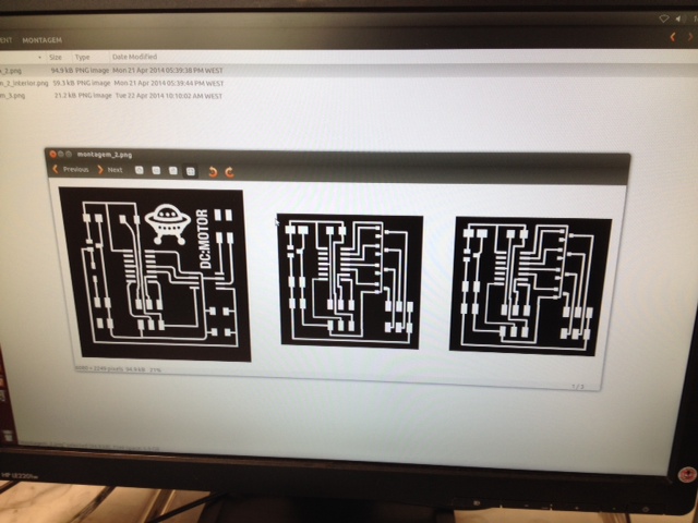
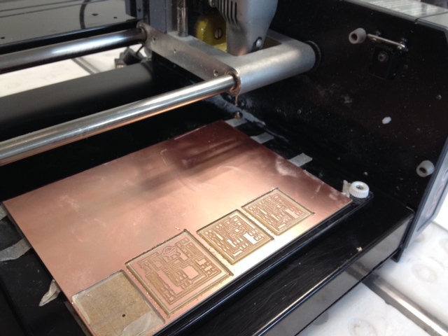
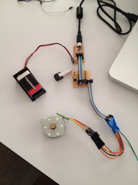
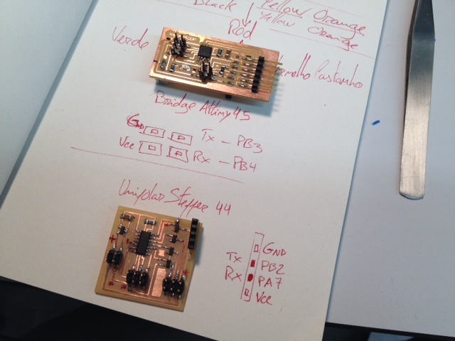
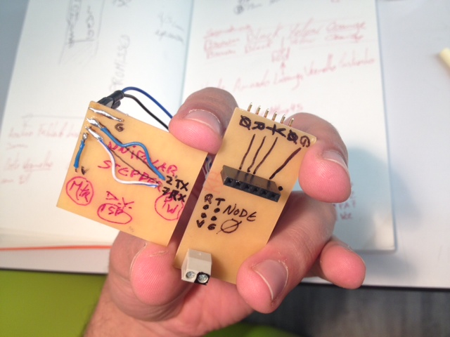
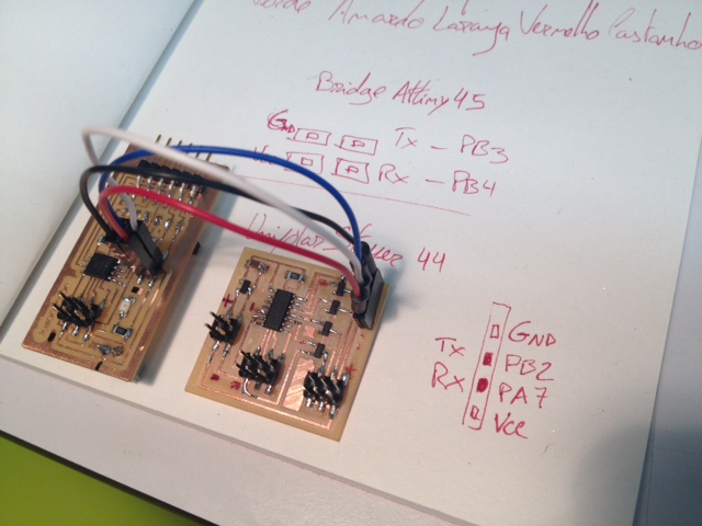
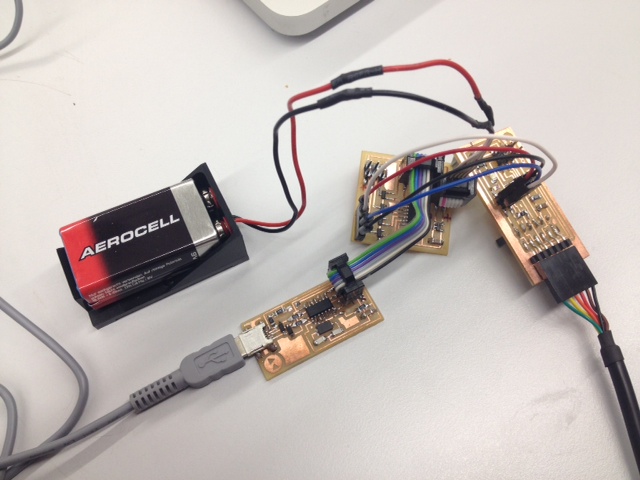
Going back to the electronics design and production week assignments skills, got both copper PBS (unipolar steppers) produced on Modela precision machine here milled at the same time next to my mate's Vasco Cosme DCmotor board:
Then programmed via fabISP:
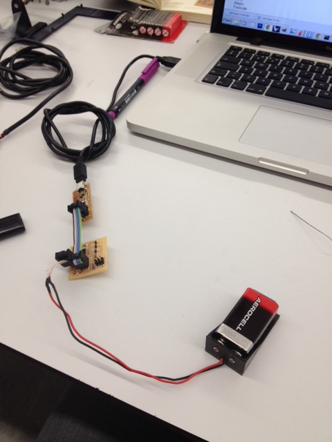
Connecting and turning on the unipolar stepper motor powered directly with a 9V battery source into the mechanical structure I could finally see some action movement:
Despite the intermittent run I guess something is still to be debugged, either the recovered stepper has no torque enough or code programming needs some lines check...
You can download the unipolar stepper Eagle and Code files here:
One idea, for controlling the two motors from the computer, would be a machine network, just like in week13. One node is connected to the computer by ftdi cable and forwards the commands to the next one. For achieving this, I started adding additional pins to the stepper boards for having TX and RX.
After programming run the program with a "blink led" test run:
Inspired by the project of Francisco Sanchez I started to change the networking code from attiny45 to attiny44. After a while I realized that this would still take quite some time and I wanted to try another way. The new idea was, by Ferdi's advice, to fabricate instead Luciano's
"Barduino" and make it controll the stepper-drivers directly.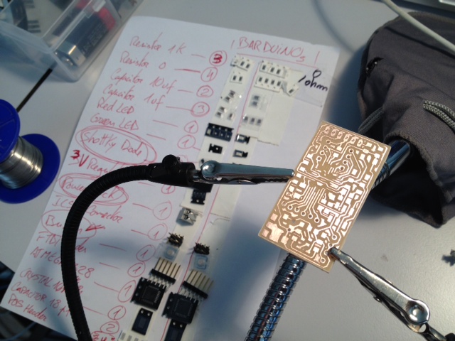
For the first time I soldered the most difficult (at least to me) microcontroller chip ever! ATMega 328 has so many tiny chip legs than the previous conquered Attiny 44!
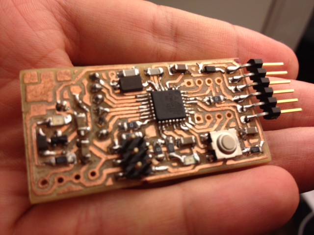
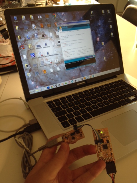
After producing two of them, one for me and another for Ferdi, did the smoke test by connecting it via ftdi cable (ground to ground) to my computer. The green led was ON meaning it´s alive ;)
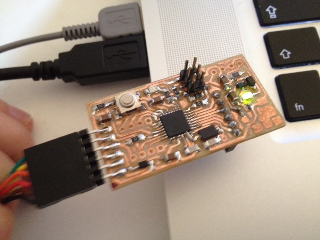
To program barduino board connected it to fabISP programmer (always check ground to ground matching first) and to the computer. On Arduino IDE selected the correct programmer from "Tools" menu (in this case fabISP) and chose "Board" according to the micro controller Arduino Pro or Pro Mini (5V, 16MHz) w/ ATMega 328. Serial Port on my case was COM17.
What happened later was odd. When uploading the "Blink" example to the board it took for ever to finish...without ever ending?!
Picking up week16 assignment, about interface and application programming, I tryed to capture the images from webcam installed and explore the results filtered by the stepresponse sensor.
In this case, input sensor values alters the cell (white squares) size according to brightness. Here's a quick video of the processing code written to input the video capture from my webcam pointing inside the kaleidoscope toy and based on the "Mirror 2" example code from Daniel Shiffman.