At this week assignment it was requested to measure something: add a sensor to a microcontroller board and measure something. I chose the promissing step-response sensor.
Like before, I started on Eagle software to practice designing the traces based on the original board leaving a larger area on the left to actuate as sensing copper surface.
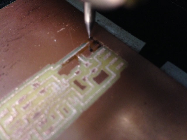
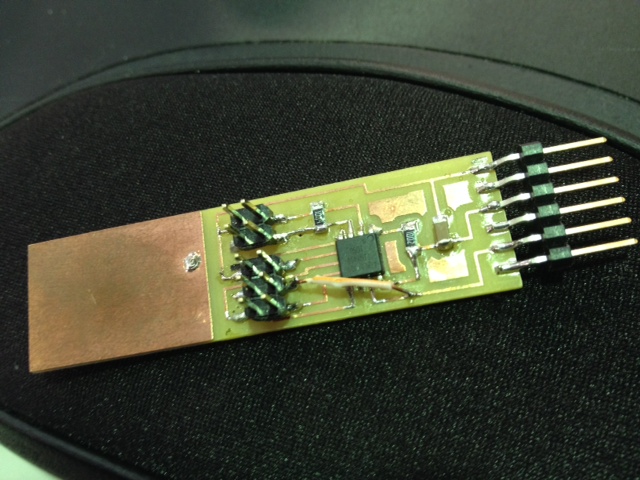
Then took right away on Modela milling the board on a FR1 copper plate that seemed never be absolute flat (at this upper right side corner).
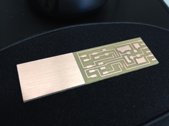
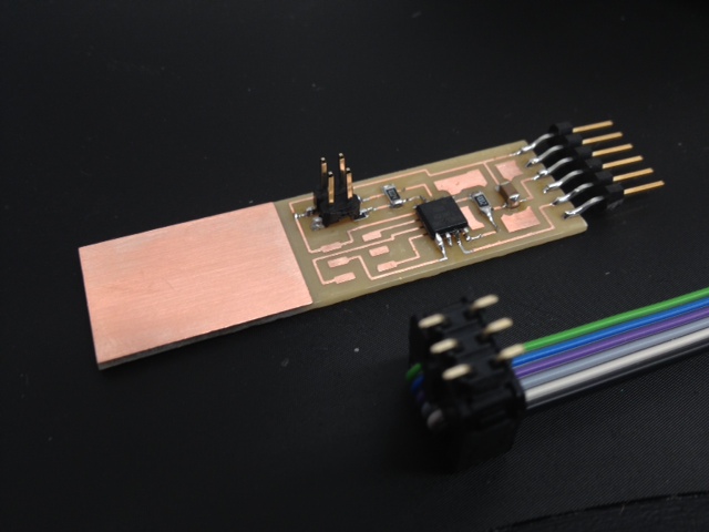
At the end it seemed very nice to look at, so sorted out on stuffing it with the components.
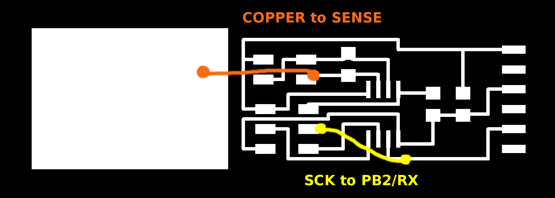
Only to realize after my mistake! With all that rush I forgot to make trace connections between SCK pin to PB2/RX trace on Eagle! What a rookie :(
Solved it by a jumper wire (upper the board)just like the connected sense pin to the left copper area (under the board).
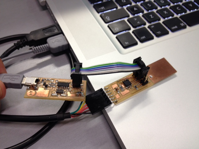
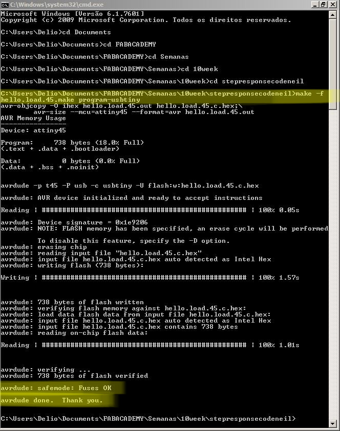
Then used fabISP board connected to the step response board to program it by inserting the CMD line "make -f hello.load.45.make program-usbtiny" from the respective folder.
For Phyton, Pyserial and Tkinter just followed fab master
"Luis Carvao"
page on his instalation process.
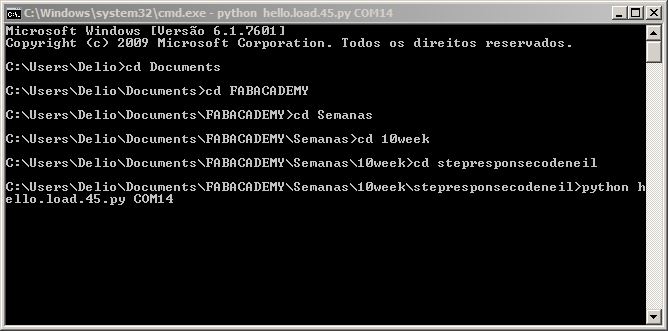
After this connect the step response board to your PC by the FTDI cable and again run the CMD line from the folder where you downloaded the python file.
At the end insert your serial port number accordingly, in my case was COM14.
Finally the step response sensor will display different values when you press it.