Embeded programming:
This week assignment was requested to read a microcontroller data sheet and to program the Hello Button+LED board to "do something".
I took the guide lines on the, once again, always well documented and precious Providence tutorials on how to program our Hello Button + Led Board using Arduino IDE 1.0.5r2 version software.
Also download and install the respective Attiny zip board files to your computer, unzip, rename it as "hardware" and locate it on the Arduino local folder.
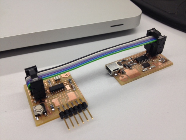
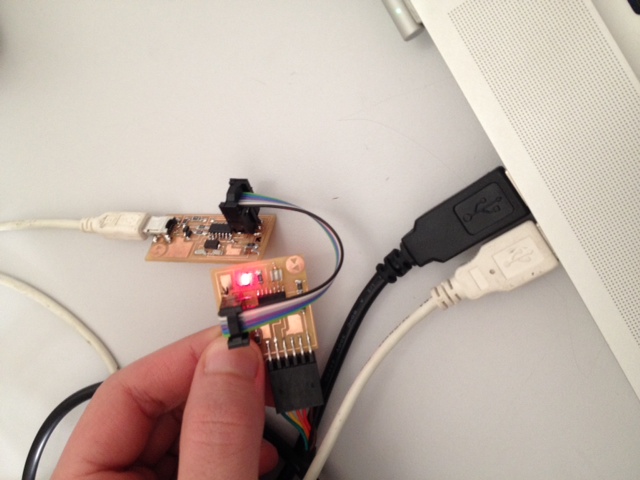
To start, we need the FabISP in-system programmer made on week 4 and our Hello Button+Led Board made on week 6
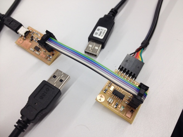
Get an microUSB cable to power the FAbISP and a FTDI cable 5V (also download and install FTDI cable drivers to your OS from
here ) to connect the Hello Button+Led Board both linked with a flat 6 wire cable right in place (first checked and marked with a black marker pen both ground pins to make sure if ground is always connected to ground)
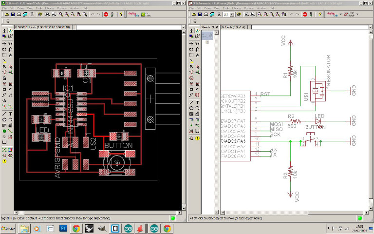
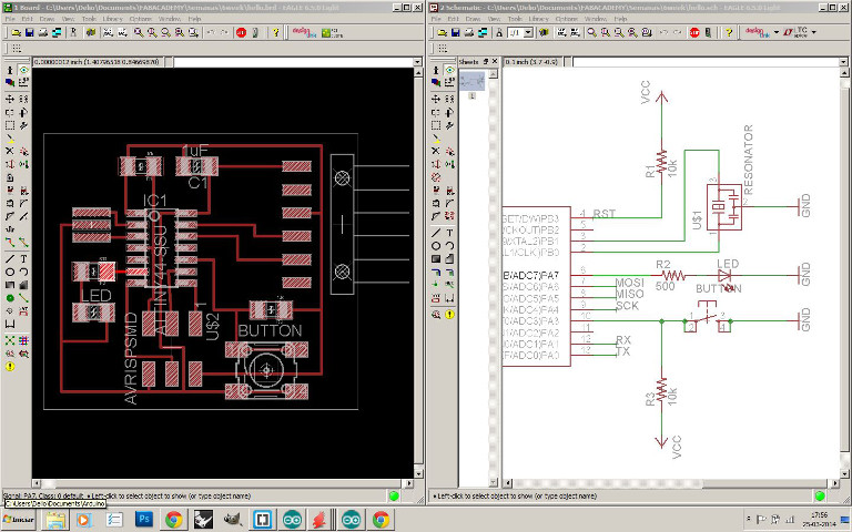
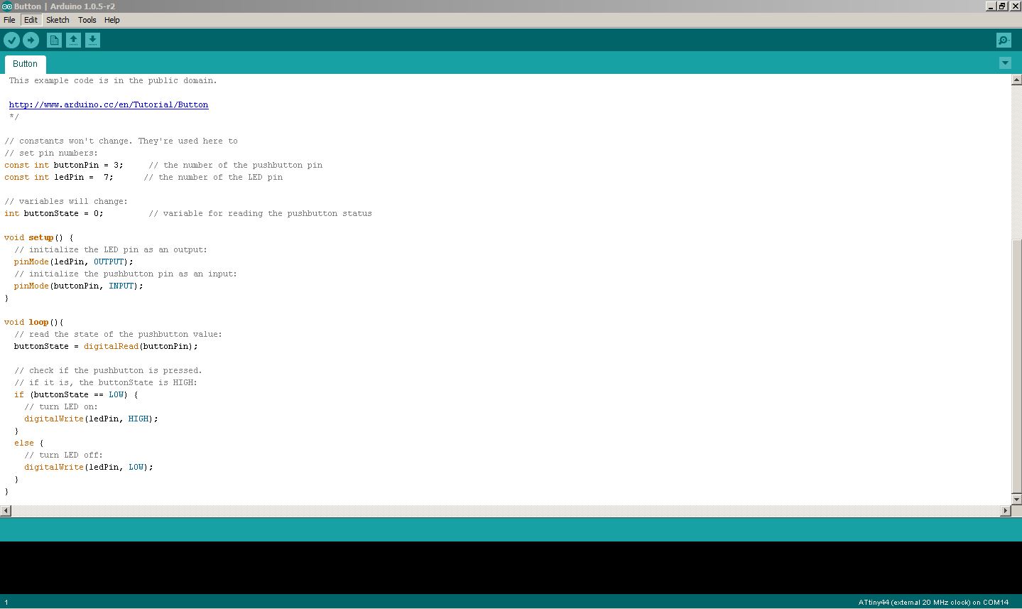
With the help of your previous designed HB+LED Eagle board and schematic file check the right correspondant pin number for either the Button and the LED, on my case was 3 and 7 respectively.
Here is all my components and cables ready to connect:
Restart Arduino IDE and select Tools_Board_ATtiny44 (20MHz) now and again Tools_Programmer_USBtinyISP and set Tools_Serial Ports_(select your serial port)
With all components well connected and identified its all ready to program.
First on Arduino IDE select Tools_Burn Bootloader. This message should appear: "Done burning bootloader".
Now we can upload a program into the board by open the File_Examples_Digital_Button and changing the pin numbers by default on Arduino to the correspondant ones on our Hello Button + LED board.
At the end LED is ON when button is pressed ;) I will further explore more on writting code when I got more time on my side...