Electronics Production:
On this assignment it was requested to make the FabISP in-circuit programmer.
This week for me was a true challenge. It was the first time I got in touch with electronics and I confess it was a struggle only surpassed with the kind help from my others fab mates and the fab masters valuable guidance.
Therefore, here at FablabLisboa chose to
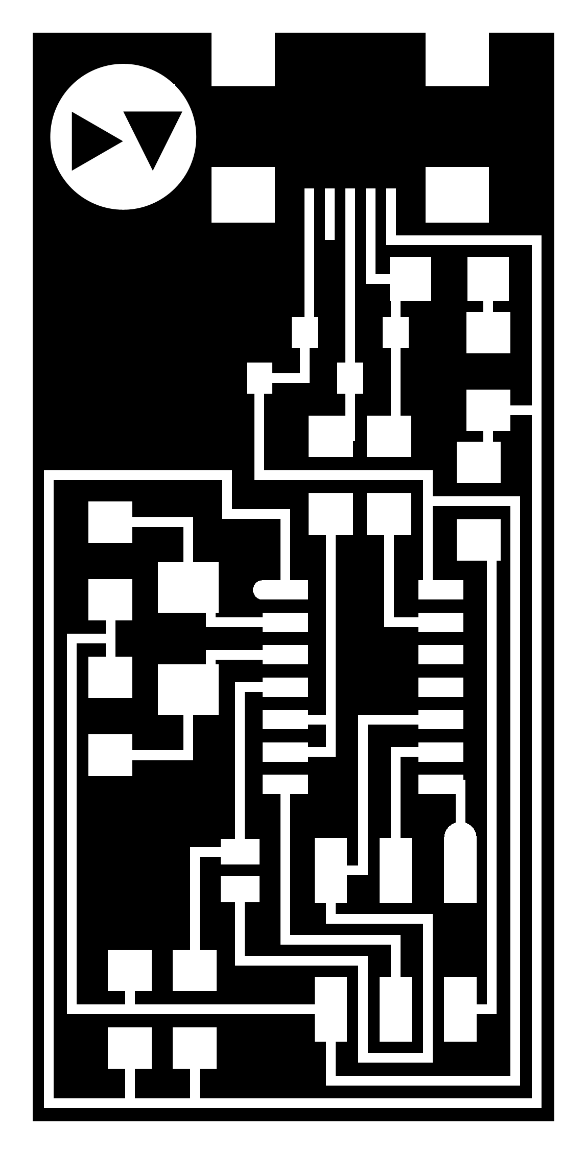
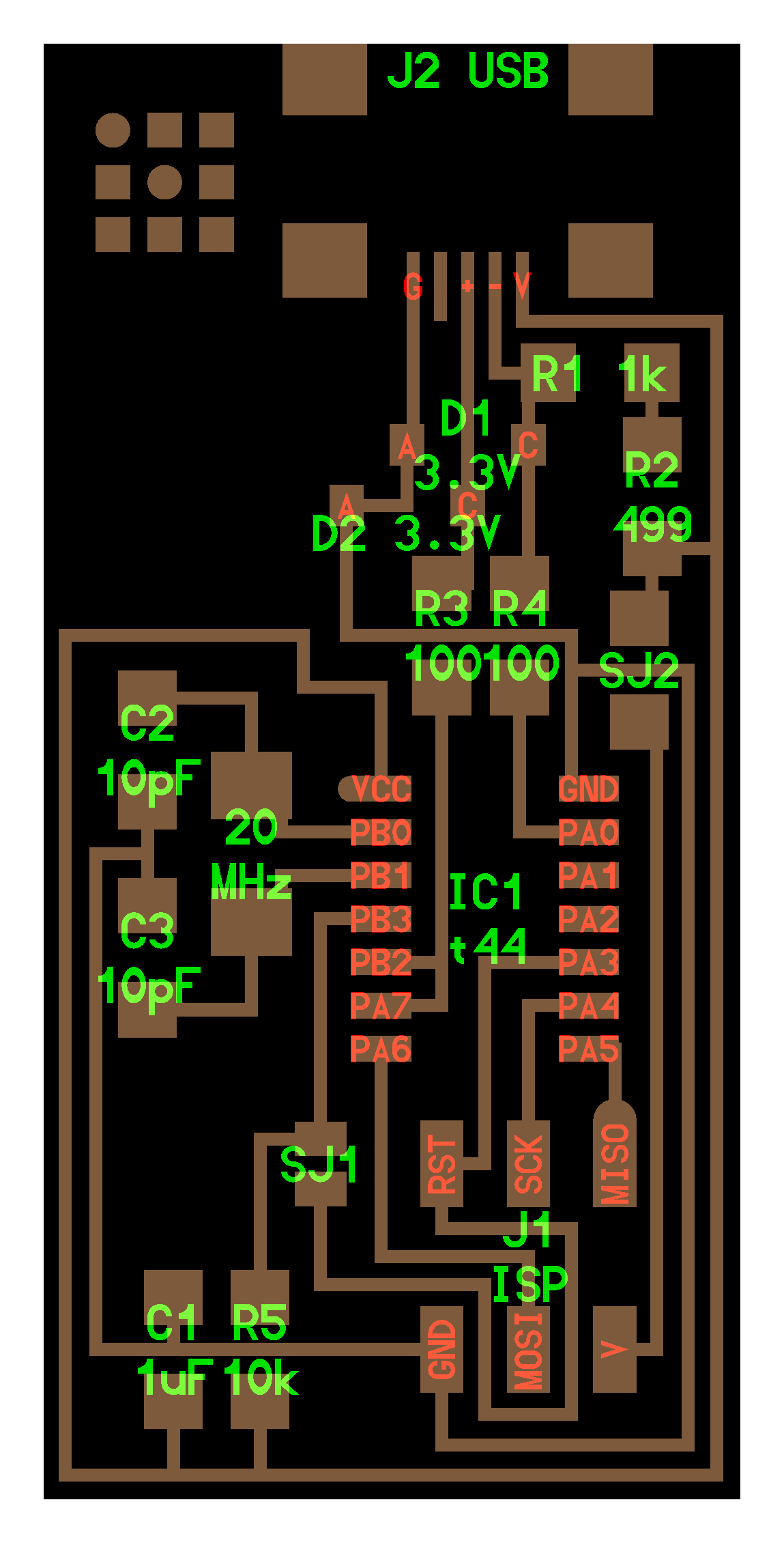
produce the FabISP parts layout (20mhz crystal) on FR1 (phenolic paper) using the interior image png reference where each student defined their own logo for later proper identification. I chose my initials DV as two triangles inside a circle.
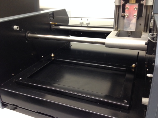
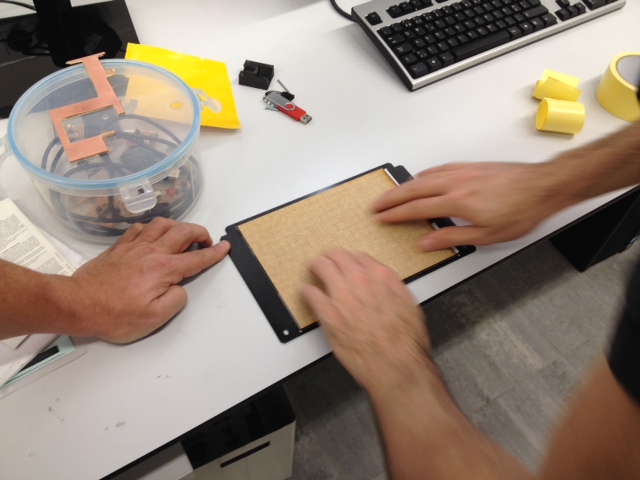
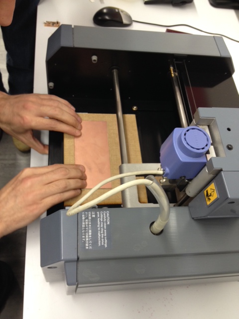
Before staring to work with the Modela precision milling machine its better to clean up milling area and base plate properly (acetone is ok for all metal surfaces) from dust or glue residues that could alter the flatness of the printed circuit board (PCB).
One "sacrificial plate" was previous laser cutted from 3mm MDF to protect eventual drill bit errors damaging the main Modela base plate. To fix these two and the FR1 plate set to milling we apply double sided tape carefully checking some glue residues that may alter, once again, the FLATNESS of the PCB is CRUCIAL!
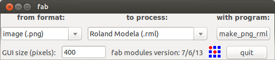
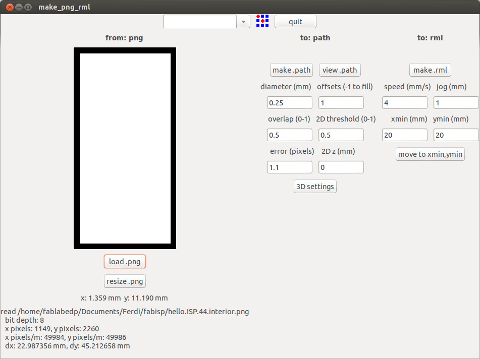
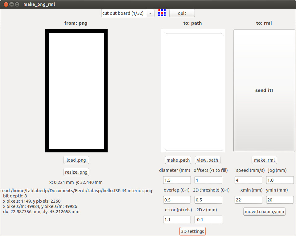
Next on the launch fab-tool select to make_png_rml from the hello.ISP.44.interior.png file
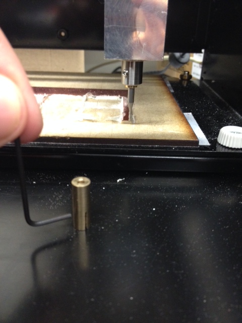
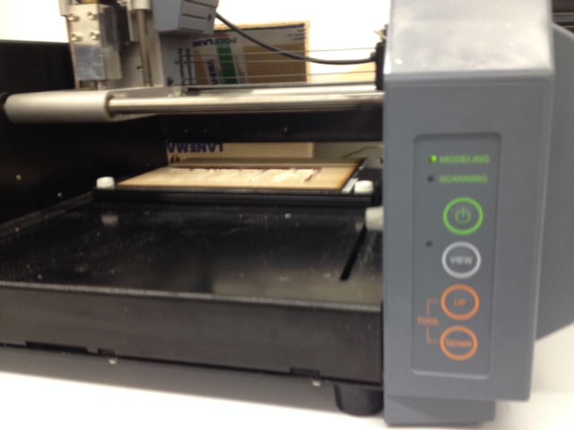
Change the mill bit on the Modela for one of 0,25mm by unscrewing/screwing correctly (perpendicular) to the bit socket slot.
Press (VIEW) button and then (TOOL DOWN) button SLIGHTY ONE TIME just to erase the previous drill height position.
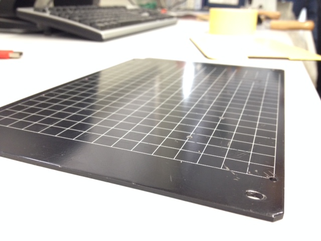
Now set new origin point accordingly pressing command "move to Xmin and Ymin" and manually with the (TOOL DOWN) button slowly down to just the FR! surface. Set up with "mill traces (1/64), diameter (0,25) offsets (1) and 2DZ (-0,0)" to test FR1 plate flatness.
Press "make.path" + "make.rml" + Send it!
In case of the FR1 is not completely flat on 2DZmm (0,0) you can mill again using an incremental value on the 2DZmm of (0,05) each time.
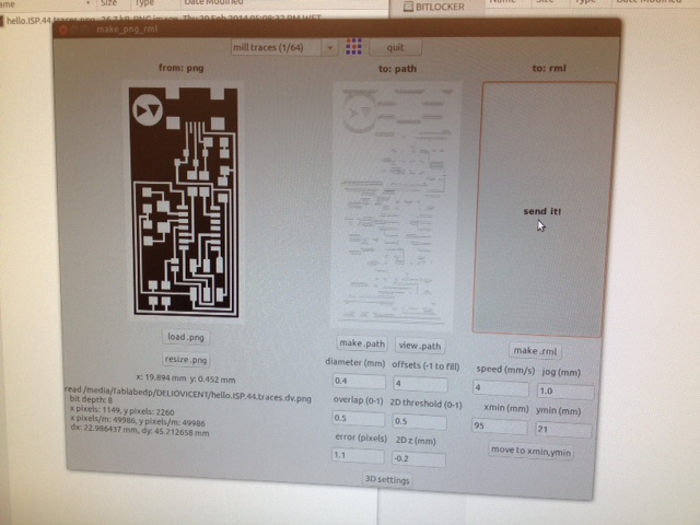
With this flatness check up done, load now the fabISP traces png file.
Note that here you change the mill preset to OTHER AND THEN CHANGE BACK again to the "mill traces" (1/64) so it can acquire new data settings to "offsets (4) "speed (3) "2DZ (-0,1).
Press "make.path" + "make.rml" + "Send it"
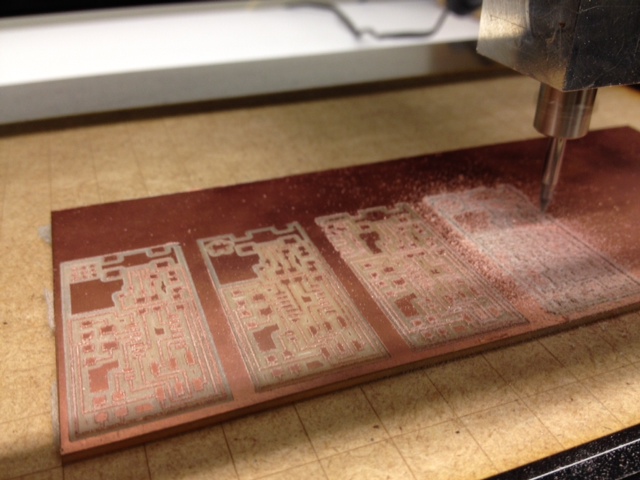
Check if the milling is uniform, if not pass again using an incremental value on the 2DZmm of (0,05) each time.
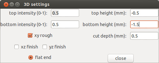
With traces milling done, load now the fabISP interior png file and chose preset to "cut out board" (1/32). Change mill bit carefully like before and change setting "diameter" (1,5) and on "3D settings" the "bottom height" to (-1,5).
Press "make.path" + "make rml" + "Send it"
Use (VIEW) button on Modela to stop milling process and on case something is not going well.
Attention when you do this cancel, open Ubuntu terminal for example, and insert sintax on the command line "ps -e | grep cat" to identify the process number rolling and then insert "kill the number of process" to eliminate the memory command on the computer. To erase data on the Modela press simultaneously buttons (UP)(DOWN) so the led under(VIEW) button flashes during 10seg. After this data on the milling machine is also clean to start over again.
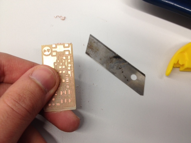
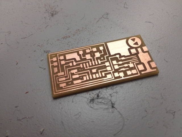
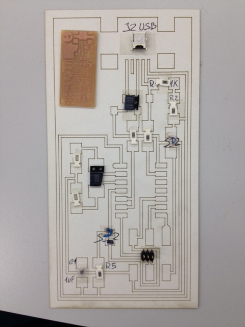
Now remove carefully the finished milled board and with a x-cutter blade scrape the surface diagonally to remove edges and using steel wood sand it a little. Now pass it on water and soap to remove grease residues (avoid touching the traces with fingers!) and there we have a nicelly clean and sparkling PCB ready to solder!
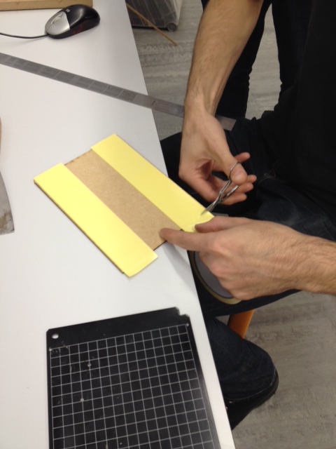
Before starting to solder prepare all the tinny components (green) needed using a double sided tape on paper to avoid losing any! Laser cutted a template on paper for visual placement guidance.
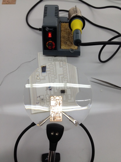
Fix the board and...good luck!
Hint: solder a little point on board where you want to put the component, then place it on position and finish soldering the rest. Repeat, deep breath repeat, deep breath...
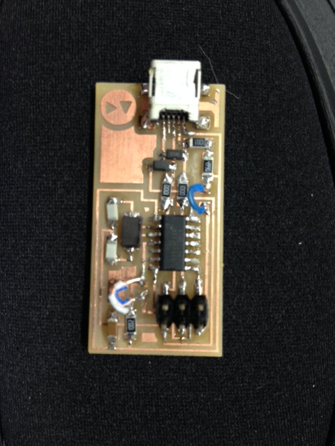
I achieve solder everything in place carefully like a "electronics surgeon" not without solder and desoldering some tricky components like the "mini USB" and the "At tinny". Pay attention to the diodes polarity (marked on each with a right line representing the positive side) and the "ground" on At tinny (marked on with a microscopic square) and avoid solder bridges between circuit traces. I used two cable wires for jumpers and soldering the final white one almost cost me the entire PCB because it started peeling the trace (it peeled cause it was suffering too much heat).
Thanks to
"MASTER JEDI FERDI"
that helped me fixed this and mannaged to putted all back in place!
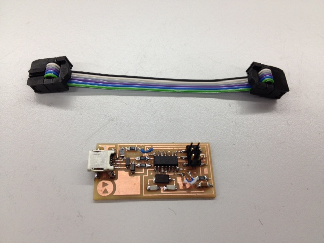
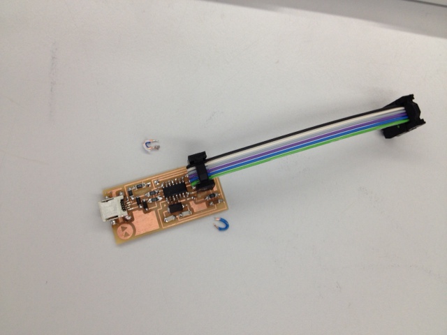
Then make a flat wire (6) cable and its all ready to program!
Before programming make a visual inspection of the board and check any solder joint that look cold (not shinny and smooth). Also use a multimeter to confirm that every connection track are connected and that "ground" and "power" are NOT.
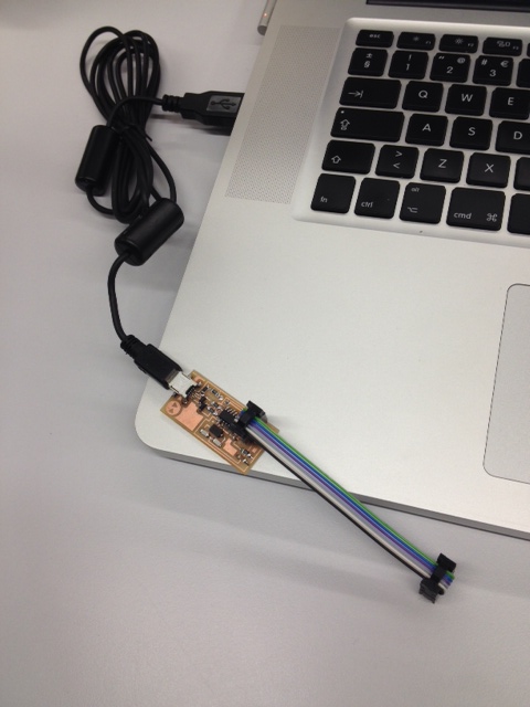
Do a "smoke test" by plugging the PCB into the computer via a mini USB cable. If no messages appear proceed to next fase.
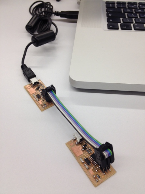
Use another programmed FabISPtiny connected to program for the first time this new one.
Im running bootcamp MAC/WINDOWS and chose to program on Mac and following the
fabacademy electronics production
tutorial by downloading and installing firmware, editing the "Makefile" Xcode
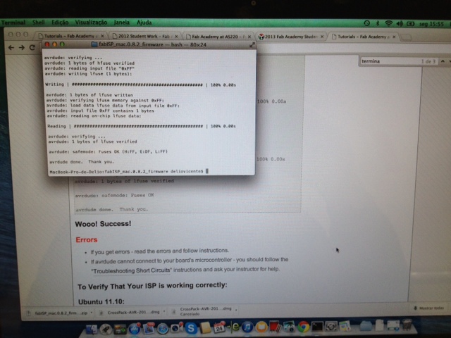
Launch terminal and move to firmware folder to type commands:
- make clean
- make hex
- sudo make fuse
- sudo make program
If all its OK a message will appear "avrdude done. Thank you."
Now just desolder the two jumpers and DONE!