Final Project
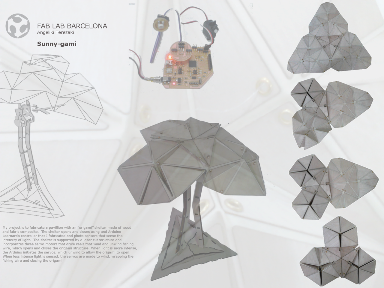
My project is to fabricate a pavillion with an “origami” shelter made of wood and fabric composite. The shelter opens and closes using and Arduino Leornardo controller that I fabricated and photo sensors that sense the intensity of light. The shelter is supported by a laser cut structure and incorporates three servo motors that drive reels that wind and unwind fishing wire, which opens and closes the origami structure. At the top, the columns are connected to the superstructure via a stiff transition piece. This piece was fabricated using a double elements in the composite and placing epoxy resin on the entire surface, so that it is quite stiffer than the rest of the origami superstructure. This was done so that the whole superstructure does not move when the mechanism is in motion and to allow easier movement of the fishing line at this junction (so that it does not tangle).When light is more intense, the Arduino initiates the servos, which unwind to allow the origami to open. When less intense light is sensed, the servos are made to wind, wrapping the fishing wire and closing the origami.
The project is based on Ron Resch's Origami Tensselation and uses photo sensors as input to an Arduino microcontroller to automatically control opening and closing of an “origami” sunshade.
//Design included the following:
/structure (2d and 3d), mechanical design
/“origami” shade portion (composites)
/Ardunino Leonardo board (electronics design and production) and connections
/photo sensor boards (electonics design and production)
/// Electronics design and production
//Design
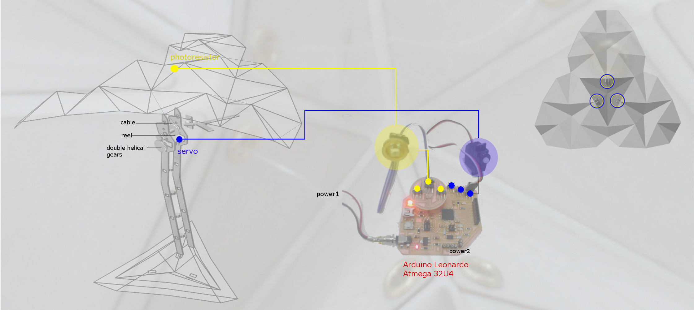
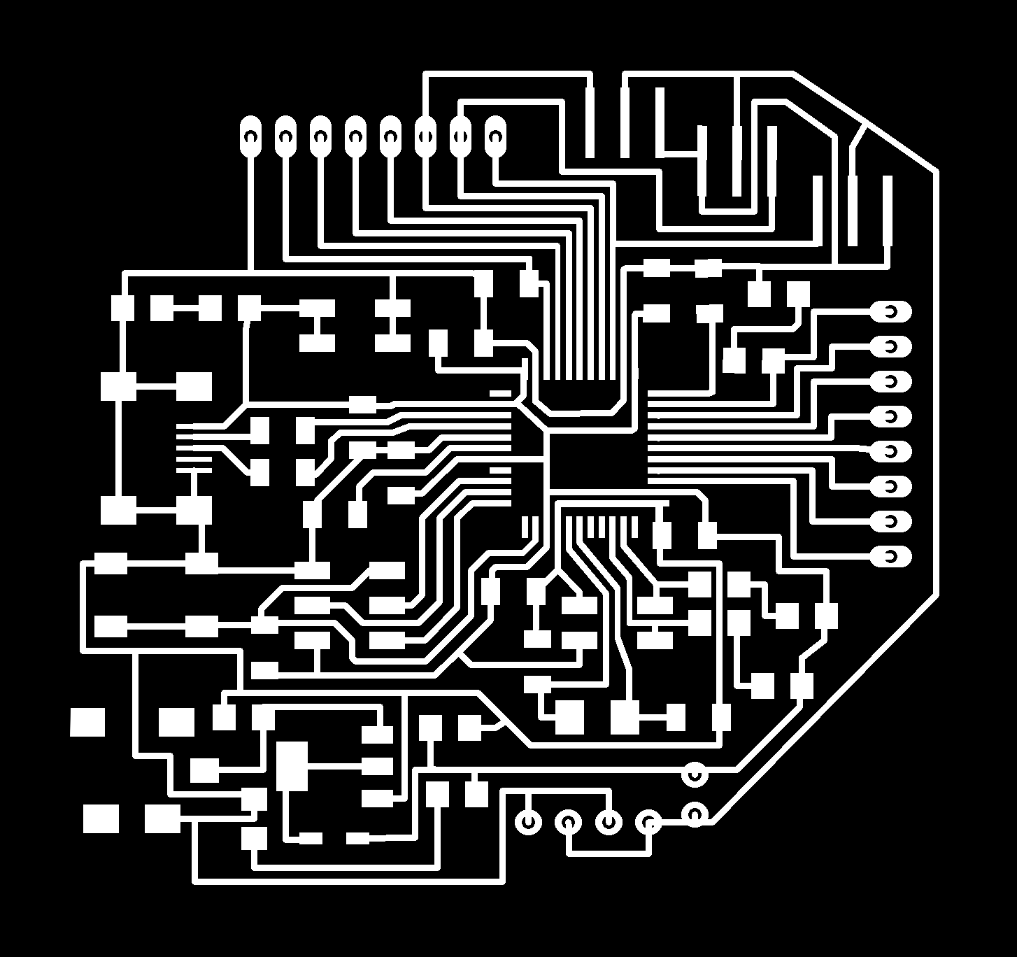
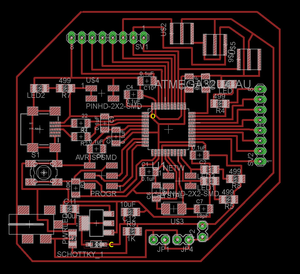
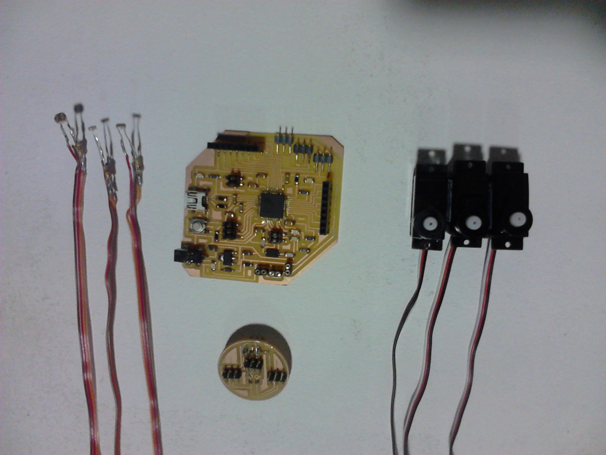
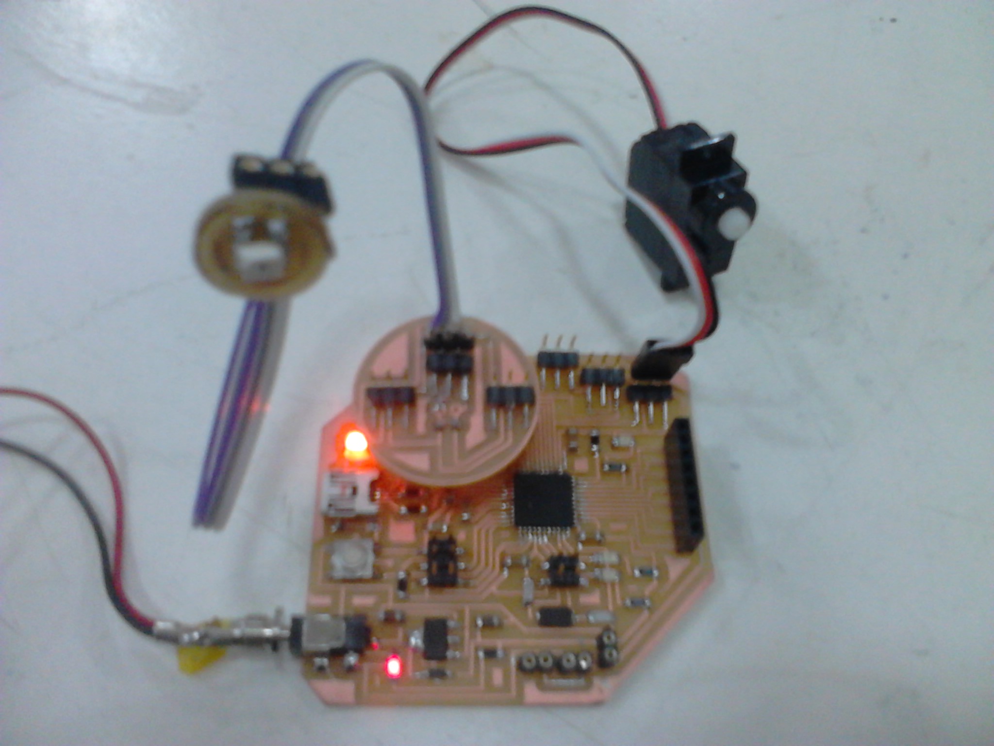
I designed and build an arduino Leonardo, that is based to "Fab Leo" that developed by Jonathan Grinham( Fab Leo). I integrated extra pins for the 3 servo motors, power jack, protection diodes, voltage regulator, power pins for the servos. I have designed a simple board that is conecting to my fabduino Leonardo in Pins A3, A5, A5(Analog pins for each sensor) and in Ground and VCC. with pins in which all the photoresistors(soldered with resistors 10k) are connecting in the pins. The sensors(input devices) are conecting to this board pins
Details about how to design a board you can find here
Leonardo with extra pins for 3 servo motors:
/32U4 processor
/resistors
/capacitors
/2 female Headers 8 positions
/pins headers female
/6pos header male
/4pos header male
/power Jack
/button
/lEDs
/usb connector
/16 MHz Crystal
/protection diode schottky
/voltage regulator
/headers/p>
/battery holder 3AAA
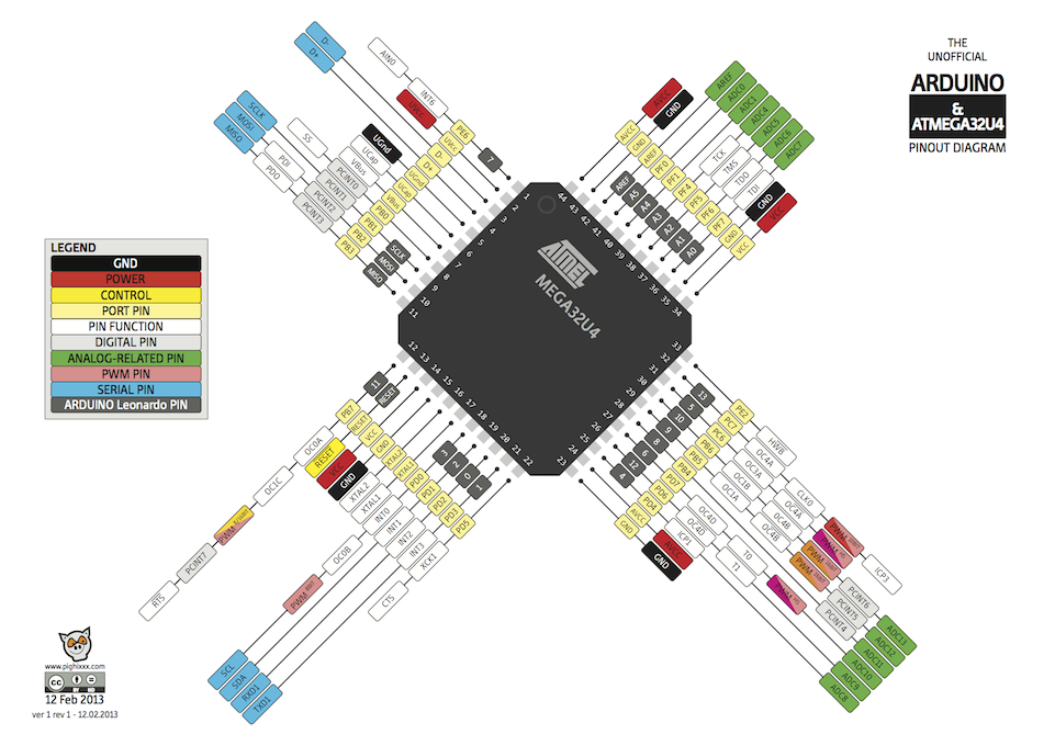
ATMEGA32U4 Pin-Out Diagram
/ Input device
Phoresistors -3
resistors - 3
/pins header male
//Milling | Soldering
Details about the milling and solder process you can find here
Download the files for milling the boards:
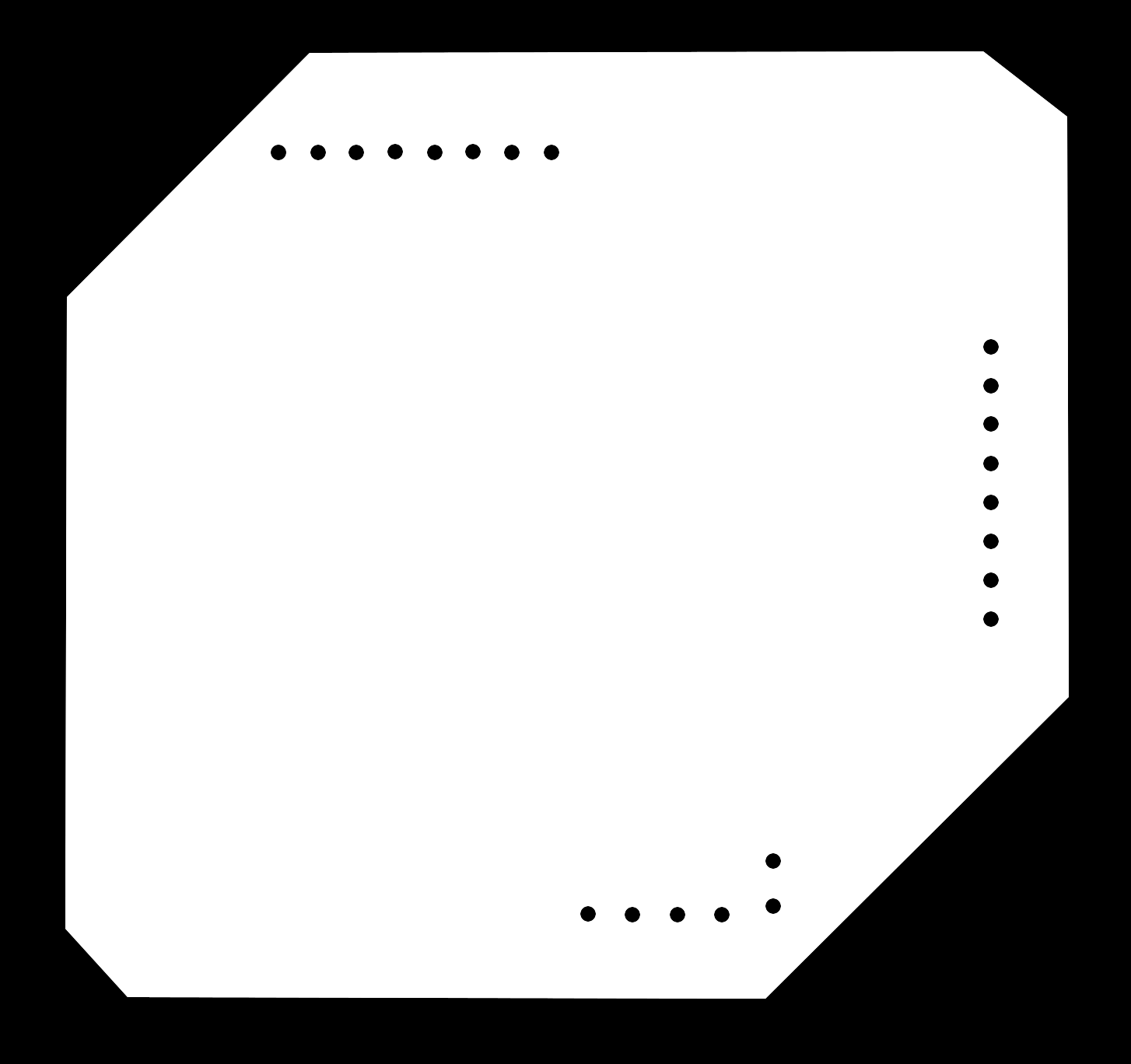
Download the board labeled diagram so that you can see where to place the components on the board
I am happy because I managed to get my new leonardo to work. I had some serial port issues that make my leonardo a bit unstable while I try to programm it through its own Usb. Some times I had to use an isp programmer or a FTDI cable to program it because the arduino was not recognized from my laptop through usb cable.. I guess that the problem is on my laptop(i am runing Windows), because if I try to programming in another computer(mac) it is working properly. I tried to udate the drivers of my laptop and this worked for some time. About the input device it worked properly at the beginning.
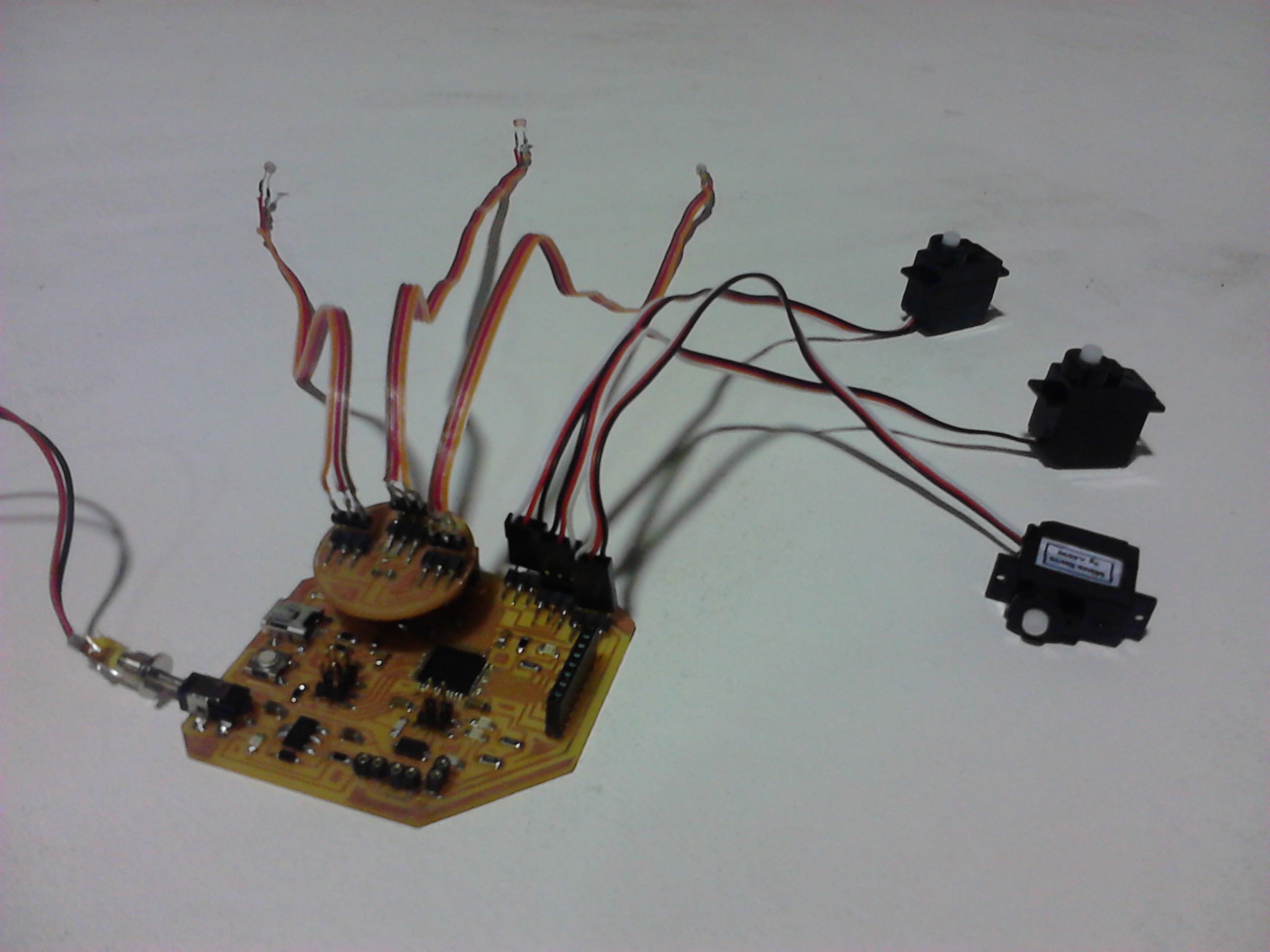
Servos are attached inn pins A0, A1, A2 and Sensors in pins A3, A4, A5. This is the
That code i used to read the value of the potentiometer (value between 0 and 1023) and then scale it to rotate the servo (value between 0 and 180). When i was trying to integrate it in my composite the sensor didn't work anymore. While I was trying to understand what happened, i realized that one connection was broken. Maybe because I pressed it a little. Unfortunately I didn't have time to fix it by the due date.
TIPS:
|It is helpful if you solder the components from inside to the outside, starting with the microcontroller
|There is a little circle on the microcontroler that should be facing to the top left if your board is oriented in the same direction as the labeled board diagram
|Diode has polarity. The "C" or cathode that is marked on the diagram, is marked with a tiny line on the component
///Laser cutting:
/Laser Milticamm 2000
Materials:
/wood veneer
/cotton based fabric
/mdf 3mm for the supports and the base
/The file for laser cutting the supports and the base you can find below. I have one layer for engraving and one layer for cutting. In Our LAB we are using the Enroute Sofware for cutting on the Milticamm 2000 laser cutter. You import the dxf file in the Enroute software. Firstly you should click on button "define layers". Select the layer for engraving.Close the window and select all the lines. Go to Transform>Merge selection. Then click on the button "Engrave" and select strategy> engrave. Close the window. Click on button "define layers". Select the layer for cutting this time and uncheck the layer for engrave . Close the window and select all the lines. Go to TRansform>Merge selection. Then click on the button "Engrave" and select strategy>cut. Close the window. Click on button "define layers" and turn on both of the layers. Close the window and click on "output options". Here we should set the strategy order, engrave should be on the top of the list, and object order, check the inside -out. Lastly check the option small parts first and click on the button "to file". Save the cut file in the dnc folder.
Now we should turn on the machine . Press Shift + home on the control to find the default home. Place the material on the bed of the machine and set the thickness of the material. Press the 0 until the sensor touch the material. Now we have to set the power and the speed for both engraving and cutting. Go to: menu>params_2d for seeting the values.
For wood is
CUT | Speed: 40, Power: 180
ENGRAVE | Speed: 60, Power: 50
For fabric is
CUT | Speed: 90, Power: 80
ENGRAVE | Speed: 100, Power: 5
Selec the file from the dnc folder and send it
TIPS:
|Make sure the material is flat on the bed of the machine
|Move the sensor in the middle of the material to set the surface
|Check if the lens is clean
|Make a test before you run the file to check the settings(go to: menu>cut util. Here you can select default shape and size for the test)
Files

///MECHANICAL DESIGN:
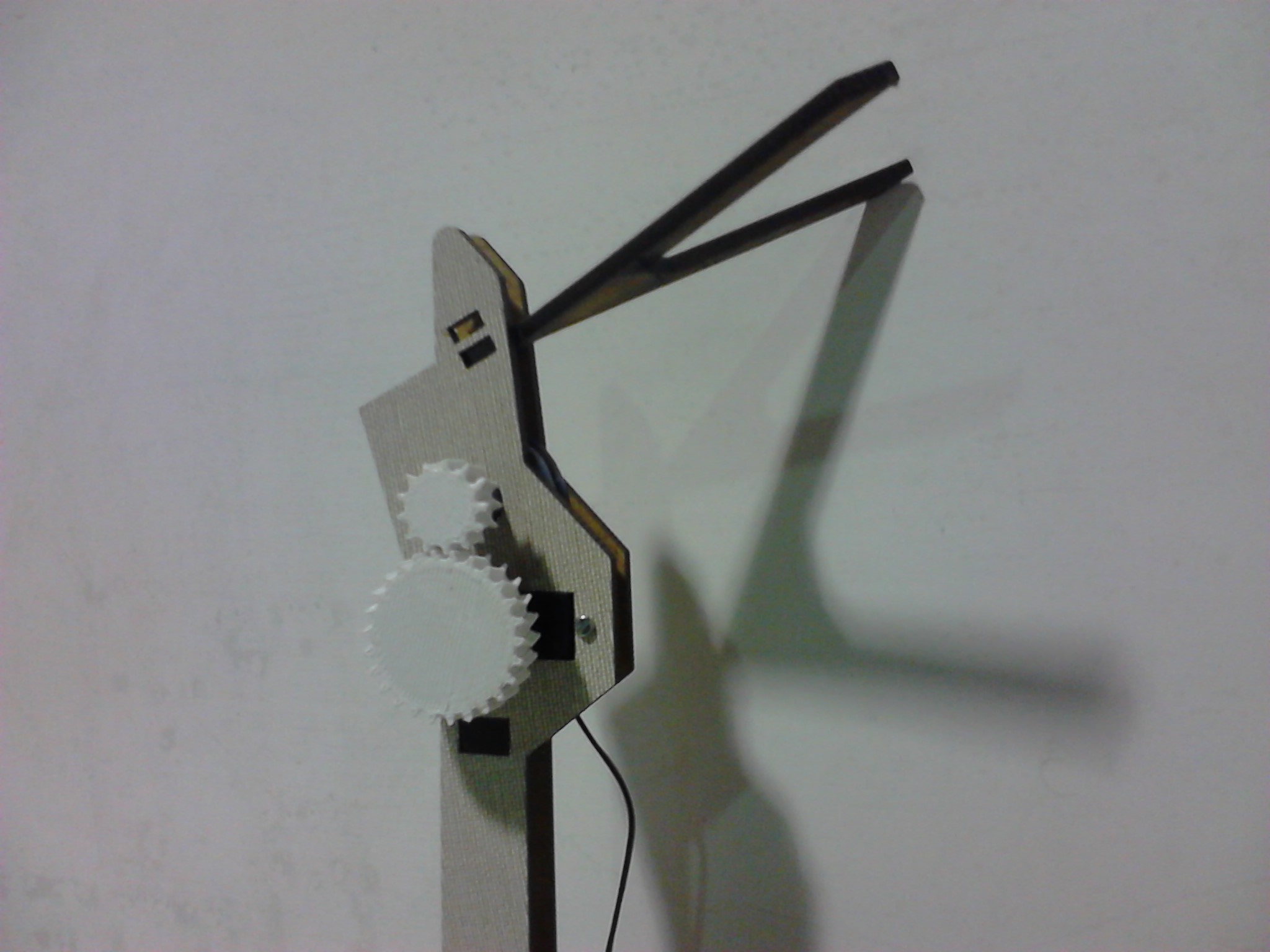
To design the 3D object I used Rhino. I designed two double helical gears, by using the "array polar" command.
Double helical gears, or herringbone gears, overcome the problem of axial thrust presented by "single" helical gears, by having two sets of teeth that are set in a V shape. A double helical gear can be thought of as two mirrored helical gears joined together. This arrangement cancels out the net axial thrust, since each half of the gear thrusts in the opposite direction resulting in a net axial force of zero. However, double helical gears are more difficult to manufacture due to their more complicated shape.
The gears are are rotating by a servo motor. The small gear is connecting with a reel and rotates twice the of the servo angle of rotation(2x180). The fishing line is wrapped around the reel. So, servo motors drive the reels,through the gears, that wind and unwind fishing wire, which opens and closes the origami structure. When light is more intense, the Arduino initiates the servos, which unwind to allow the origami to open. When less intense light is sensed, the servos are made to wind, wrapping the fishing wire and closing the origami.
//Gear
/Double helical gear
/Worm gear
Tips:
/I chose the double helical gear for both aesthetic reasons but also because it is considered stronger than a simple gear. It was, however, quite complicated to design. You have to take into account both the size of the teeth and the spacing between them. Multiple attempts were required to get the spacing between the two gears just right, so that the two gears don’t push each other away.


///3d printing:
/Makerbot_Replicator 2
Material:PLA
3d printer and PLA was used for fabricating: Three reels that are turned by a motor controlled servo mechanism, and wrap or unwrap fishing line, as controlled by the Arduino Leonardo,three reel axles for the reels to spin around, gears that connect the servos to the reels.
For 3d printing the model should be a closed mesh(repair meshes > fill holes). I exported my final 3d model as an .stl file. Files> ExportSelected > STL format. You should Uncheck Export Open Objects on the popup window.
For 3d printing the object I used the makerbot, Replicator 2 and PLA material
and makerware software.
/File > Open and choose your STL file. Click on the button “move to platform” on the popup window.
/Move or rotate your object if it is necessary.
/Click on the “Make” button.
/Click on "Make it now"
/Select The replicator 2
/I selected standard Resolution(infil10%, 0.20mm of layer height)
/Raft and supports unchecked
Materials:
PLA
TIPS:
|Check mesh and Make sure that is a closed and good mesh
|Select lay flat before you print
///Milling the mold for the composite material | Composite material:
3d milling was used for fabricating: a foam mold for assembling “origami” composite made of wood veneer, fabric and epoxy
The steps followed were:
//DESIGN MOLD
//MILLING MOLD
/Fabricate the double mold from high density foam using milling machine.
/Software:
//Partworks 2d and 3d, design software
//Shopbot 3, control software
/Tools:
//ShopBot 3 axis CNC router
//Bits 12mm and 3mm
//Drill
//Screws
Shopbot TUTORIAL
/Material:
//high density foam

// DO THE COMPOSITE MATERIAL
/Place a layer of fabric was cut to shape and placed over peelply sheet.
/Position wood veneer pieces in place (shapes to fit the origami “folds” were cut using a laser cutter) using epoxy cement to keep the two layers together(Mixing ratio 2 parts epoxy, 1 part hardener).
/Place a protective peelply textile
/A wooden spacer (made with laser cutter) used to keep the pieces in position
/Place a breather textile(allows all the air to be absorbed by the compressor)
/Place into a vacuum bag VACUUM BAGGING
/Allow to cure for six hours.
/For the stif part of my origami structure I have used the double mold to give a specific form to it. I wanted to test another technique from that of the vacuum bag. the seps are the following:
/Place a protective peelply textile(used to allow separation)
/Place a layer of fabric was cut to shape and placed over peelply sheet. Place epoxy resin on the entire surface
/Position wood veneer pieces in place (shapes to fit the origami “folds” were cut using a laser cutter) by using epoxy resin to keep the two layers together(Mixing ratio 2 parts epoxy, 1 part hardener).
/Place a protective textile
Keep the two molds together with clamps
/Allow to cure
Tips:
/Be careful in placing the epoxy to ensure that it goes where it is needed and not to get the epoxy where it does not belong.
/It is best that the vacuum bag is in good contact with all pieces of the composite surface. When there are gaps or uneven surfaces, the top part of the bag has a tendency to “bridge” and does not apply even pressure everywhere.
/Also be careful when placing the mold in the vacuum bag to protect the bag and the mold with with peelply. What the epoxy comes into contact with is very difficult to remove and trying to remove it may destroy the bag or the mold or both.

Video Gears
Video Origami
All the Files: