Final project - Design for happiness
One thing all humans have in common is that each of us wants to be happy. However, sometimes we need a stoplight and figure out what makes us happy. The happiness lamp will help you slow down and step back in this fast paced life. It helps you notice your personal needs, and above all, it is a reminder of what makes you truly happy.
What is the happiness lamp exactly?
When researching the topic design for happiness I was trying to figure out how to measure happiness. First of all I started with researching techniques such as an EEG scan or ECG scan but in that sense happiness is something hard to grasp. However when thinking a bit more about it happiness was quite clear to me. Happiness is a persons needs being satisfied.
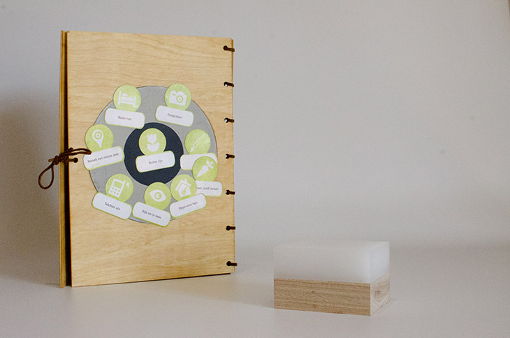
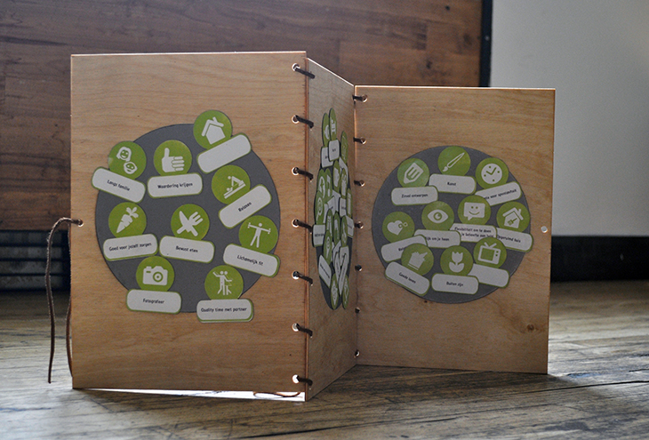
For a project concerning this needs a colleague and I created a booklet. The book is an object where you could sort your personal needs by importance. We noticed that this had a good influence on the persons happiness. It made the user reflect and think about their own happiness and needs. There was only one problem, at a certain point the user forgets about the book its existence. This is how I decided to create the happiness lamp, a lamp that notifies you to think about your personal needs.
Self build lamp:
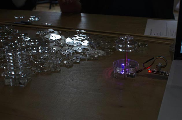
A wired lamp that the user can plug into your computer. The lamp is customisable, the user can build your own shape with the use of geometrical shapes from acrylic. This was the first model created. I wanted to let the user have a really personal unique object that they would get attached to. Because of this I wanted to give the user the option to build their own small lamp as a fun object to play around with. As a result of the size of the lamp I wasn't able to create a wireless connection. Because of this the lamp needs to be wired to a computer.
Bill of materials:
- Acrylic 950mm x 440mm x 4mm €22,-
- 4mm round wood (http://www.houthandelschmidt.nl €1,- per piece)
- 8mm round wood (http://www.houthandelschmidt.nl €1,- per piece)
- 4mm triplex (http://www.houthandelschmidt.nl €18,- 240mm x 122mm x4mm)
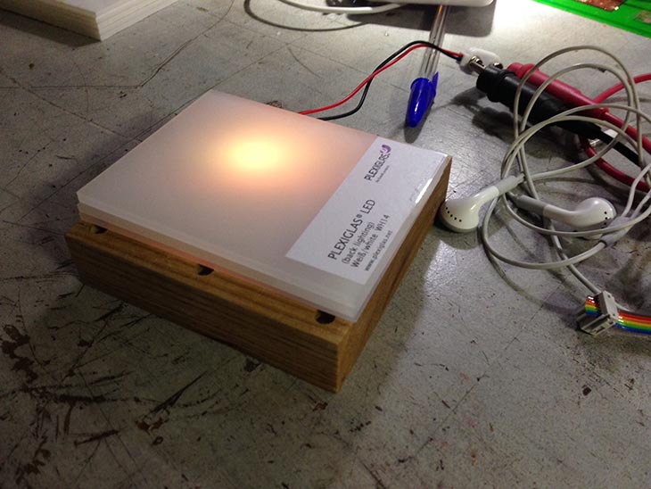
- PLEXIGLAS® LED, block, White WM51 GT 385 x 360 mm €71,40 (but I used a sample)
- Electronics (http://www.farnell.com)
- 2x ATTINY84 MCU, 8BIT, ATTINY, 20MHZ, SOIC-14 €7,68,-
- 2x RES 10.0 OHM 1-4W 1% 1206 SMD €0,16
- 5x CAP CER 0.1UF 250V 10% X7R 1206 €1,35
- 2x 3.3v Regulator €1,56
- 2x NRF24L01+ 2.4GHz Antenna Wireless Transceiver $3.41
- 1x Battery holder €0,57
- 1x 2X03SMD€0,89
- 1x RGB LED €0,48
- 1x Double sided FR1 $0.64
- 1x FTDI Cable €17,95
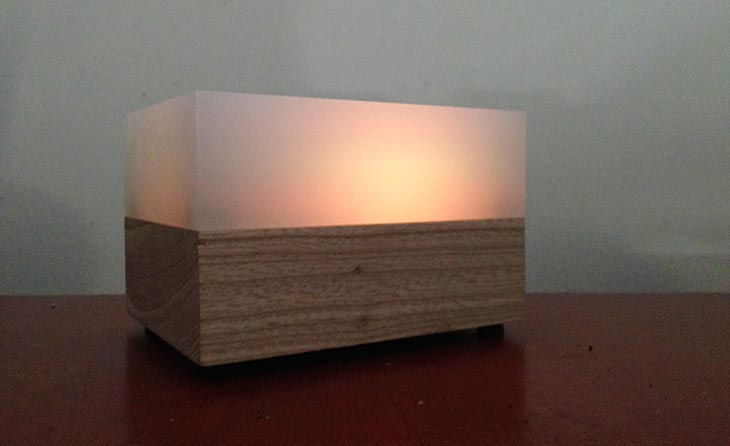
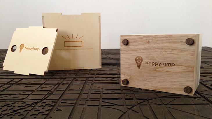
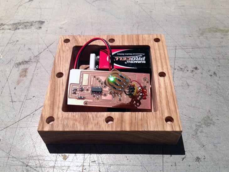
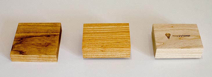
Pre build lamp
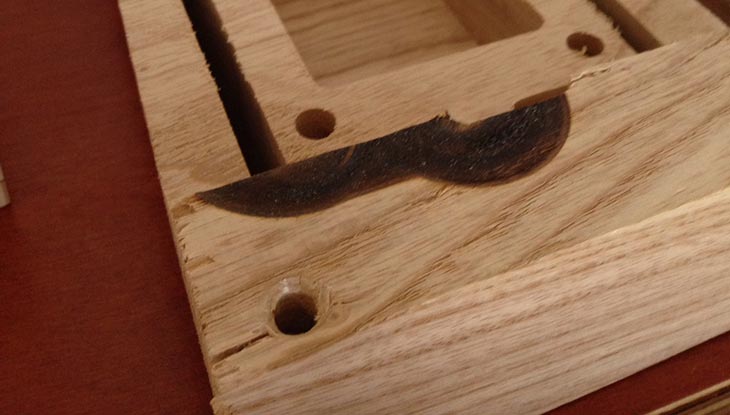
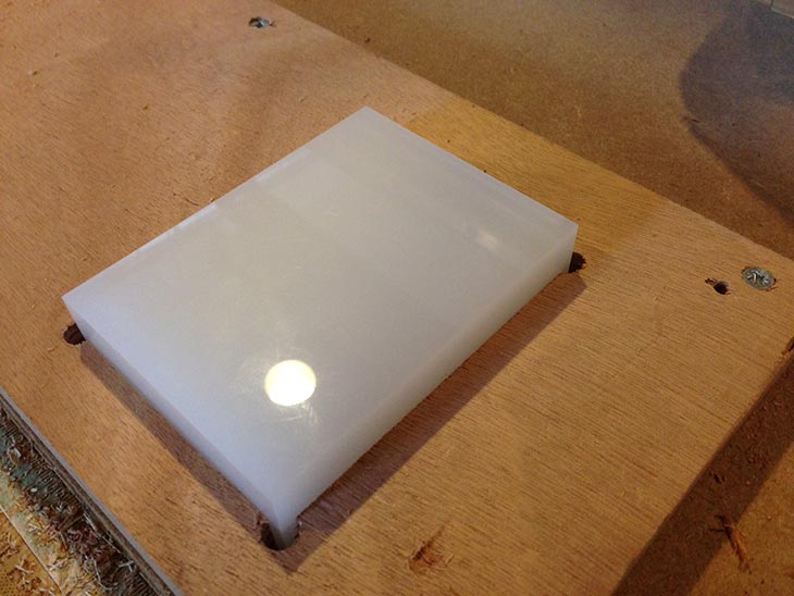
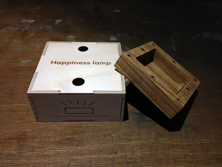
This lamp is already made and does not have a custom shape. The lamp is made out of one big piece of satin acrylic and one piece of ash wood. The ash wood is milled out into a casing for the electronics. The lamp is a standalone object powered by a 9V battery. The lamp receives it's data wirelessly from a computer that has the wireless transmitter connected. Aesthetics where very important for this object as it should be a likeable object that the user want to put on his or her desk.
What parts and systems will be made?
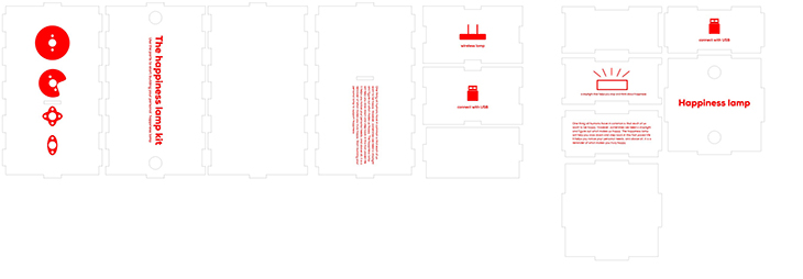
- Packaging
- Circuit boards
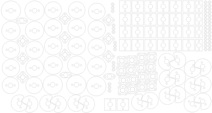
- Lamp construction-kit parts
- Interface to set the lamps colours
What processes will be used?
- Laser cutting
- Electronics design
- Electronics production
- Embedded programming
- Networking
- Interface and application programming
- 2D design
- Milling
- Surface finishing
Check out the Applications and implications over here
Invention, intellectual property, and income here
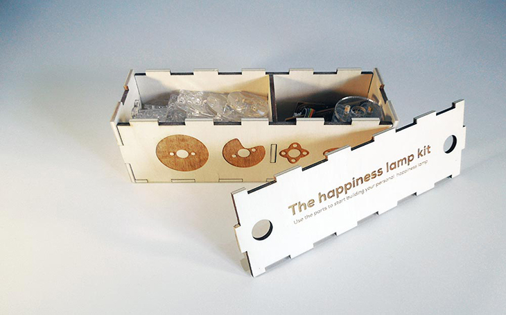
Laser cutting
I created the package and engraved the logo into the casing with the laser cutter.
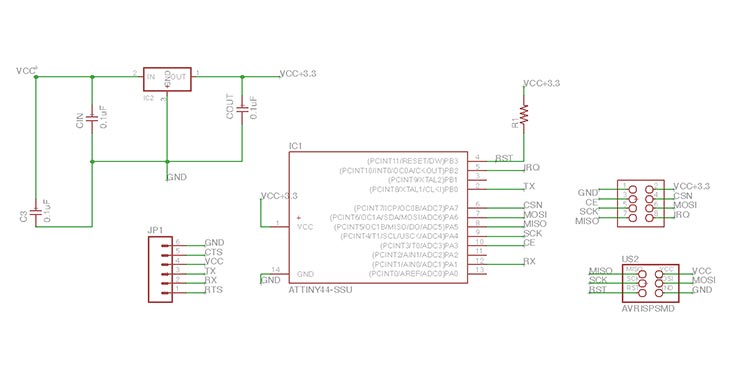
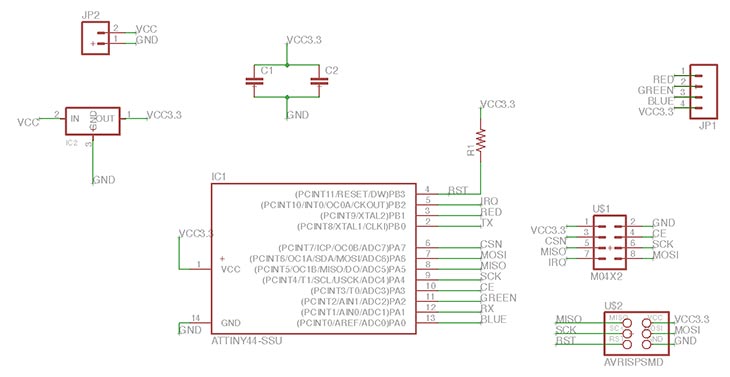
Electronics design
I designed two custom boards for receiving and transmitting data over a wireless connection. For this I used the nRF24L01(+) 2.4GHz Wireless Transceiver.
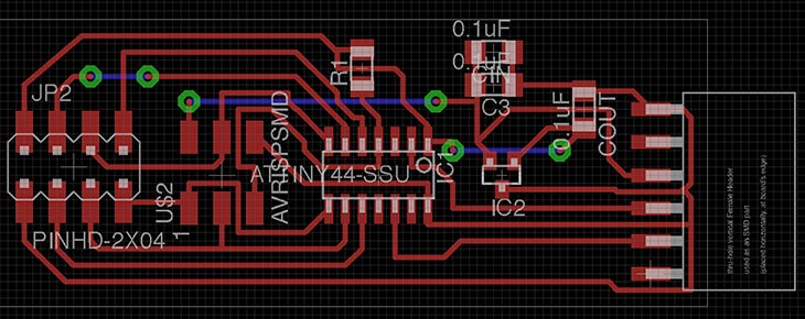
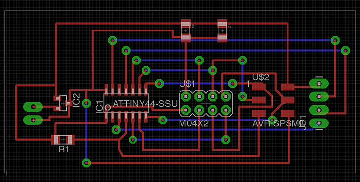
Electronics production
With the use of the Roland Modela I created the two circuit boards. This process is now really familiar to me and everything went well. Maybe I could have used a newer milling bit so the lines would be a bit more precise.
Embedded programming
For the programming I created some software to wirelessly send data from my computer. Also because I did not have enough PWM pins available I needed to implement software PWM to be able to use all the colours of the RGB led.
#include <SPI85.h>
#include <Mirf.h>
#include <MirfHardwareSpi85Driver.h>
#include <nRF24L01.h>

#define CE    7
#define CSN   3

// ATMEL ATTINY84 / ARDUINO
//
//                           +-\/-+
//                     VCC  1|    |14  GND
//  SerialTx   (D  0)  PB0  2|    |13  AREF (D 10)
//             (D  1)  PB1  3|    |12  PA1  (D  9)
//  RESET              PB3  4|    |11  PA2  (D  8)
//  PWM  INT0  (D  2)  PB2  5|    |10  PA3  (D  7)  CE
//  SS/CSN     (D  3)  PA7  6|    |9   PA4  (D  6)  USCK
//  USI-DI     (D  4)  PA6  7|    |8   PA5  (D  5)  USI-DO
//                           +----+


int redVal = 0;
int greenVal = 0;
int blueVal = 0;
int next = 0;

int ledPinRed = 1;
int ledPinGreen = 8;
int ledPinBlue = 10;

int bufferSize = 0;
char buffer[32] = "";
unsigned int counter = 0;
uint8_t nodeID = 0;

void setup(){
  Serial.begin( 9600 );    // for tiny_debug_serial

  Mirf.cePin = CE;
  Mirf.csnPin = CSN;
  Mirf.spi = &MirfHardwareSpi85;
  Mirf.init();

  pinMode(ledPinRed, OUTPUT);
  pinMode(ledPinGreen, OUTPUT);
  pinMode(ledPinBlue, OUTPUT);

  Mirf.setRADDR((byte *)"serv1");
  //Mirf.payload = sizeof(char);
  Mirf.payload = 4;

  Mirf.config();

  Serial.println("Listening...");

  redVal = 0;
  greenVal = 0;
  blueVal = 0;
}

void loop(){
  byte data[Mirf.payload];

  if(!Mirf.isSending() && Mirf.dataReady()){
    Serial.println("Got packet");

     Mirf.getData(data);

    if (data[0] = 255){
     redVal = data[1];
     greenVal = data[2];
     blueVal = data[3];
    }


  Mirf.send(data);
  }
//  redVal = 120;
//  greenVal = 250;
//  blueVal = 10;
  setRed();
  setGreen();
  setBlue();
}


void setRed(){
    if(redVal == 0){
      digitalWrite(ledPinRed,HIGH);
      return;
    }
    else if(redVal == 255){
      digitalWrite(ledPinRed,LOW);
      return;
    }
    // On period
    for (int x=0;x<redVal;x++){
    digitalWrite(ledPinRed,LOW);
    }
    // Off period
    for(int x=0;x<(255-redVal);x++){
    digitalWrite(ledPinRed,HIGH);
    }
}

void setGreen(){
    if(greenVal == 0){
      digitalWrite(ledPinGreen,HIGH);
      return;
    }
    else if(greenVal == 255){
      digitalWrite(ledPinGreen,LOW);
      return;
    }
    // On period
    for (int x=0;x<greenVal;x++){
    digitalWrite(ledPinGreen,LOW);
    }
    // Off period
    for(int x=0;x<(255-greenVal);x++){
    digitalWrite(ledPinGreen,HIGH);
    }
}

void setBlue(){
    if(blueVal == 0){
      digitalWrite(ledPinBlue,HIGH);
      return;
    }
    else if(blueVal == 255){
      digitalWrite(ledPinBlue,LOW);
      return;
    }
    // On period
    for (int x=0;x<blueVal;x++){
    digitalWrite(ledPinBlue,LOW);
    }
    // Off period
    for(int x=0;x<(255-blueVal);x++){
    digitalWrite(ledPinBlue,HIGH);
    }
}
#include <SoftwareSerial.h>
#include <SPI85.h>
#include <Mirf.h>
#include <MirfHardwareSpi85Driver.h>
#include <nRF24L01.h>

SoftwareSerial mySerial(0, 9); // RX, TX

#define MAXBUFF 4
#define CE    7
#define CSN   3

// ATMEL ATTINY84 / ARDUINO
//
//                           +-\/-+
//                     VCC  1|    |14  GND
//  SerialTx   (D  0)  PB0  2|    |13  AREF (D 10)
//             (D  1)  PB1  3|    |12  PA1  (D  9)
//  RESET              PB3  4|    |11  PA2  (D  8)
//  PWM  INT0  (D  2)  PB2  5|    |10  PA3  (D  7)  CE
//  SS/CSN     (D  3)  PA7  6|    |9   PA4  (D  6)  USCK
//  USI-DI     (D  4)  PA6  7|    |8   PA5  (D  5)  USI-DO
//                           +----+

byte buffer[MAXBUFF];
byte bufferSize = 0;

byte bufferRec[MAXBUFF];

void setup()
{
Mirf.cePin = CE;
Mirf.csnPin = CSN;
Mirf.spi = &MirfHardwareSpi85;
Mirf.init();
Mirf.setRADDR((byte *)"clie1");
Mirf.payload = MAXBUFF;
Mirf.config();

mySerial.begin(9600);
}

void loop()
{
  Mirf.setTADDR((byte *)"serv1");
  if (mySerial.available() > 0)
  {
    buffer[bufferSize++] = mySerial.read();
  }

if (bufferSize >= MAXBUFF)
   {
     Mirf.send(buffer);
//     for (int i = 0 ; i < bufferSize;i++)
//     {
//     mySerial.write(buffer[i]);
//     }
     bufferSize = 0;
  }

//if (Mirf.dataReady())
//{
//  Mirf.getData(bufferRec);
//    for (int i = 0 ; i < MAXBUFF ; i++)
//    {
//     mySerial.write(buffer[i]);
//    }
//}
}
Networking
With the use of the nRF24L01(+) 2.4GHz Wireless Transceiver and the mirf library I setup a wireless connection between two board. The lamp and the computer.
Interface and application programming
For the interface I created a simple interface with three sliders in processing. In the future I would like to be able to use the interface designs I made of the whole platform.
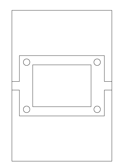
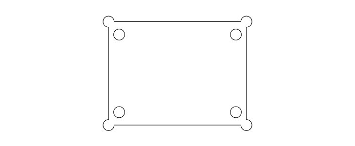
2D design
For the Shopbot I created a 2D design of my 3D model this because I prefer to use the partworks2d software for the Shopbot.
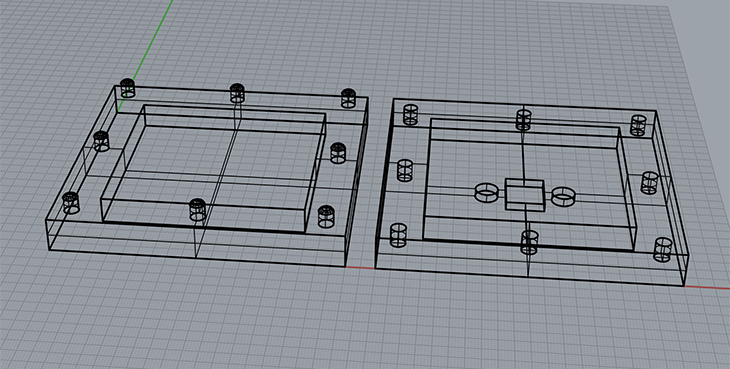
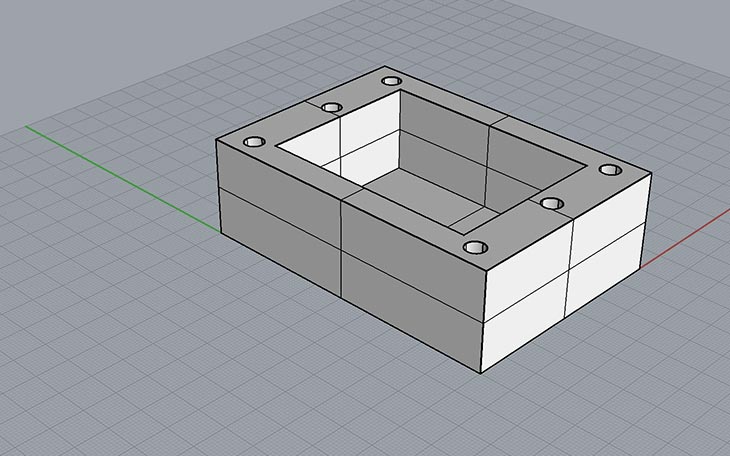
3D design
With rhino I created a 3D model of the casing to get an idea of the electronic casing. I made two models because the first model was to big for the acrylic. This because to buy custom cut acrylic was to expensive.
Milling
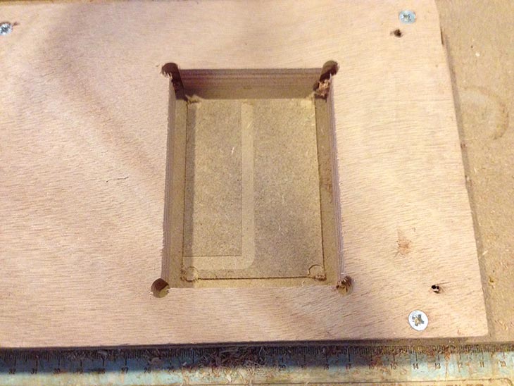
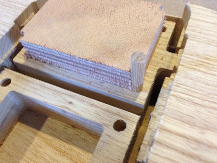
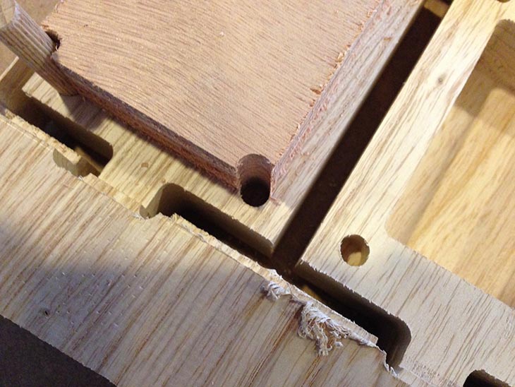
Other images:
Next prototype steps:
- Expand the interface
- USB transmitter (design already made)
- Casing for USB transmitter
- Casing for the FabtinyStar (used for the wired lamp)