Embedded Programming
Task:
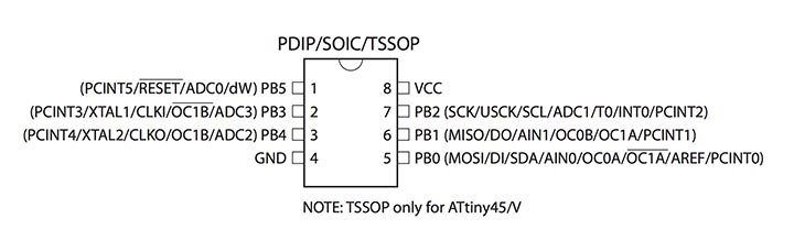
read a microcontroller data sheet, program your board to do something, with as many different programming languages and programming environments as possible
Description:
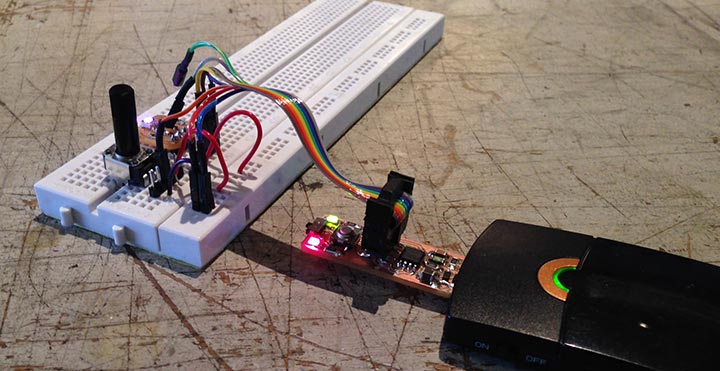
I have been working during this assignment on my final project, my final project makes use of programming and electronics. I programmed the Fabtinystar I made with the use of the Arduino IDE. I added a potentiometer that can give an analog input to one of the LEDS of RGB and this way I can start mixing colours for the happiness lamp.
What did I do:
- Download CrossPack for AVR
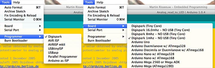
- Install DigisparkArduino
- Connect potentiometer to RGB LED
- Program the electronics using the DigisparkArduino IDE
I download DigisparkArduino through this website and added it to my application folder. I used this IDE to program my FabtinyStar that I made earlier, check it out here. I also setup AVR using this tutorial and CrossPack for AVR. Before I could use the DigisparkArduino to program my FabtinyStar I istalled the micronucleus bootloader on the my board using another FabtinyStar programmer.
Materials:
- Breadboard
- Cable
- Potentiometer
- FabtinyStar
- RGB LED Breakboard
My arduino code:
/* Analog Read to LED
 * ------------------
 *
 * turns on and off a light emitting diode(LED) connected to digital
 * pin 13. The amount of time the LED will be on and off depends on
 * the value obtained by analogRead(). In the easiest case we connect
 * a potentiometer to analog pin 2.
 *
 * Created 1 December 2005
 * copyleft 2005 DojoDave
 * http://arduino.berlios.de
 *
 * Edit by MartinR 2014
 * http://www.martinr.nl
 */

int potPinRed = 1;    // select the input pin for the potentiometer
int ledPinRe = 0;   // select the pin for the LED red=0 pin1 green=1 blue=3
int ledPinGr = 1;
int ledPinBl = 3;
int ledPin = ledPinRe; // what LED the potentiometer gives an analog value
int val = 0;       // variable to store the value coming from the sensor

void setup() {
  pinMode(ledPin, OUTPUT);  // declare the ledPin as an OUTPUT
  pinMode(potPinRed, INPUT);  // declare the ledPin as an OUTPUT
}

void loop() {
  val = analogRead(potPinRed);    // read the value from the sensor
  analogWrite(ledPin, map( val, 0, 1023, 0, 255));  // turn the ledPin on
}
I found this code at the arduino website
Assignment images:
Next steps:
- Design boards more suited for my program
- Attach three potentiometers instead of one.
- Make the redesigned RGB LED board I already made and document it
- Make it work without a breadboard
Conclusion:
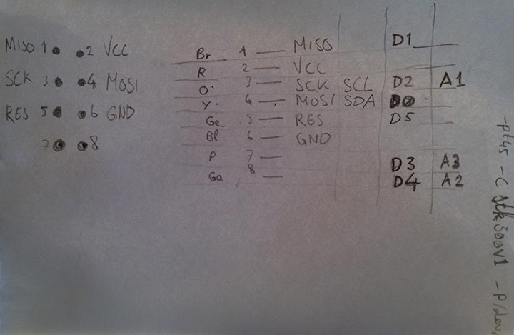
It's really important to understand the datasheet and how to connect everything. I found it handy to make a schematic of the wires and what they are connected to.