|
|
FAB ACADEMY 2014 | MIGUEL PEZO |
|
Electronics Design 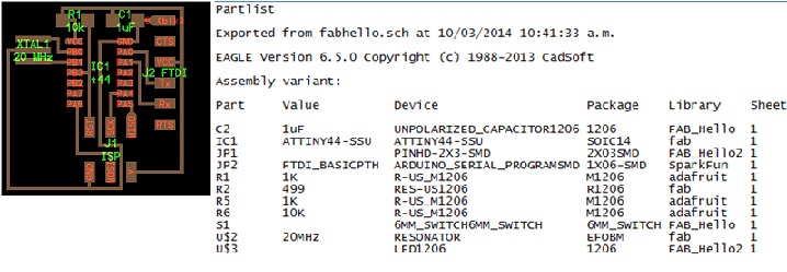
The assignment this week was to modify the hello.FTDI (link) board by adding at least a button and a LED to it. This required re-drawing the base hello.FTDI board in a PCB design software before being able to mill it again with the added components. I used "eagle" and I did it in 3 parts ,Design, Milling and Soldering
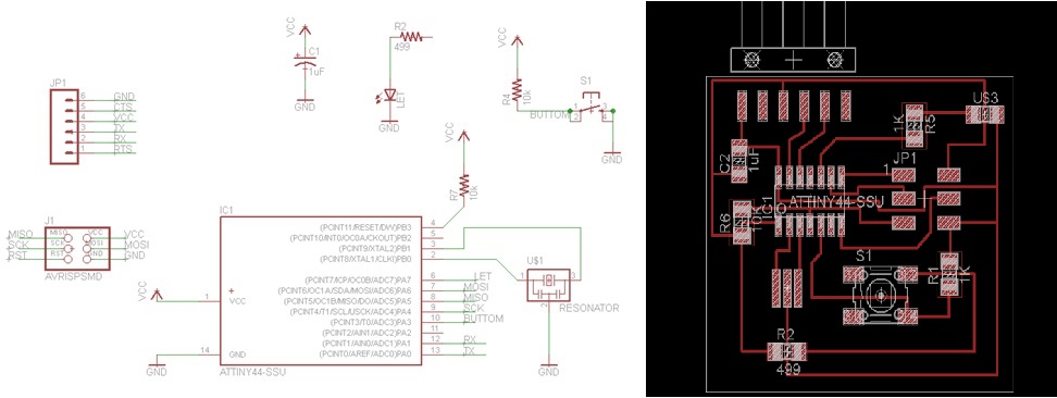
Design
Eagle has libraries that contain information about each component: geometric layout and logical output pins. Components used at Fablabs were not available on the already-installed libraries, so I had to install the Fablab components library first.
Wiring is really a form of art, and takes a long time to master properly. Following the original Hello.FTDI board wiring it was possible to route the board without any extra overlapping wires
I exported images: File->Export. Settings: Monochrome ticked, resolution 500 DPI
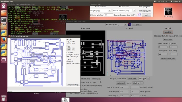
Milling
After creating the PGN file, go to mill card , for this use the following parameters :
Used Roland Modella
Sets " -Z = 0.12" and " offsets = 2" (the offset is the time to pass the mill ) , select option "mill tractor 1/64 ) finally the option " make path "
Sets the X and Y axis in ny case ( 20 , 13 ) will be Observed as the trace and select "make rml "
We click on "Send it "
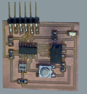
Soldering
The welding process, is very difficult because the components are very small, a first card could not be used because of problems of distances between lines.
The second card was more appropriate and with it the card is full.
|