ASSIGNMENT
Make something big.
WHAT I DID
- I learned how to use ShopBot
- the task of the week: make something big!
SHOPBOT
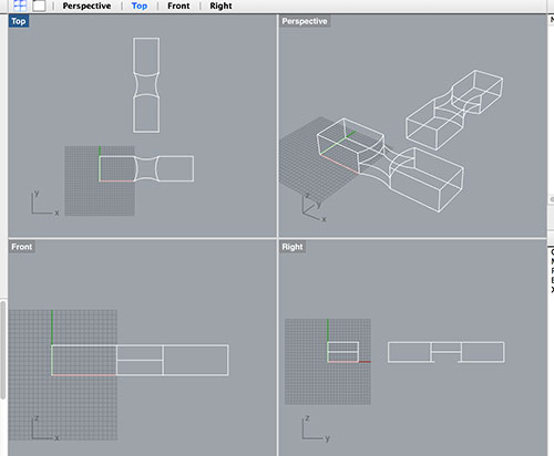
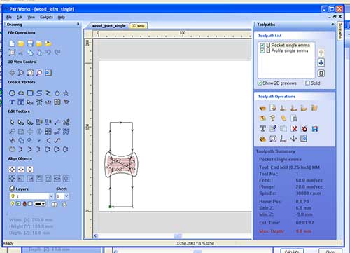
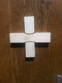
To get familiar with the ShopBot I decided to try a wooden joint. From http://www.flexiblestream.org/project/50-digital-wood-joints I downloaded the 50 digital wood joint and selected one of them:
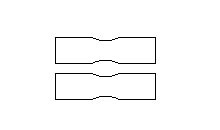
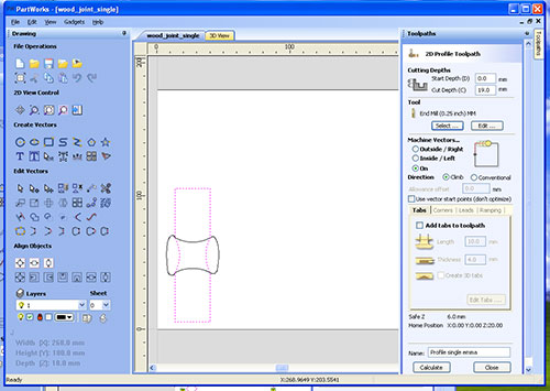
The 2D file simply appears:
but to create the right path for the milling machine I adjusted the file like follows:
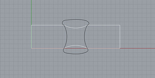
The black path is the pocket path and the white one is the cutting profile.
My how-to-do steps for the big milling machine are:
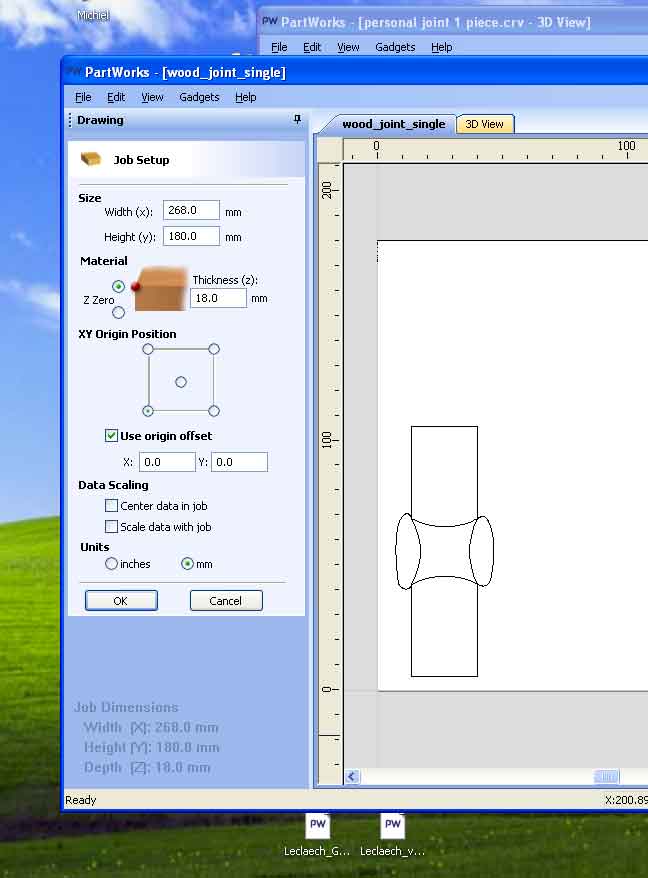
---- I open Pathwork v2 software
---- Set-up panel:
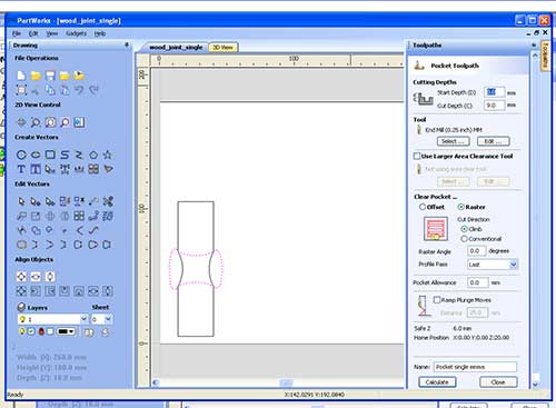
---- I create the toolpath, one for each job (in my case two: profile and pocket)
---- Select: to select the profile bit I'm going to use.
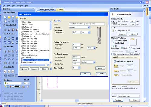
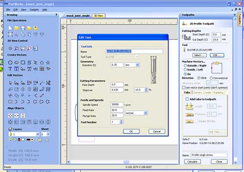
---- Edit: to edit the features of your job releated to the bit.
---- Calculate: to generate the path.
---- Select the toolpath you are going to save and take care to select the right format: .sbp.
---- Open ShopBot
---- Open Keypad
---- I set my origin (XY) and I take a picture of the absolute value of my origin!!!!!
---- I set the Z calibration: take the metal pannel, check the short with the mill bit (if the green light on the window blinky), hold the metal pannel on the working panel and under the bit, press Z button and wait the mill bit will move twice touching the metal panel that you have to keep with both hands on you working board.
---- I move to my origin the bit.
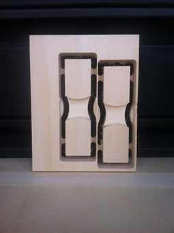
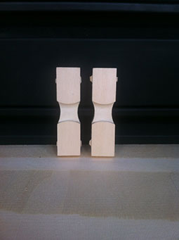
The result of the milling is the following:
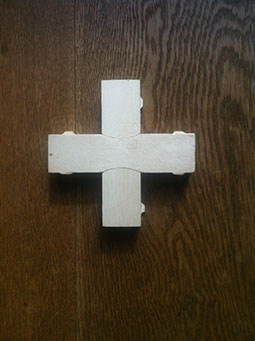
and this is one of the mistake I have done:
In this case when I created the profile path I selected the option: Machine Vector on, the mill bit moved on the path instead outside the path and so I cutted more then I wanted, generating the offset you see in the picture.
Tips
- flutes 1/2 for big and not accurated milling; for precise jobs 3/4 flutes are better.
- if during the milling job the machine stops (it can happen for several reason like elettric drop or comunication problems with the computer) it's important to take note of the line where the job ended. Then you can start the same job with the option: "start from the line" from the File menu. I suggest to move the bit close to the working area and start the job from two lines before the one you wrote down. For istance if the line stopped at line 200, I would start the new job from line 198. It's also important that the XYZ calibration is still the same so always check if the machine kept it.
TEAM PROJECT
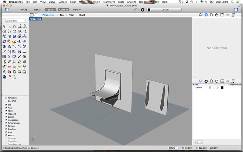
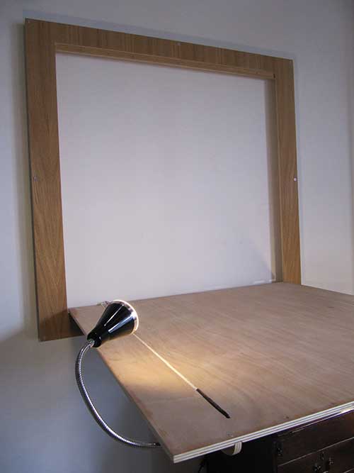
The task of the week was "make something big!". We worked like a team, Martin and I. We wanted to make a photobot table that:
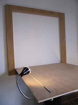
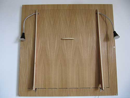
So we agreed to make a foldable tabel with automatic light. At first we wanted implement foldable arms but it was not so easy to make it so we moved to this model:
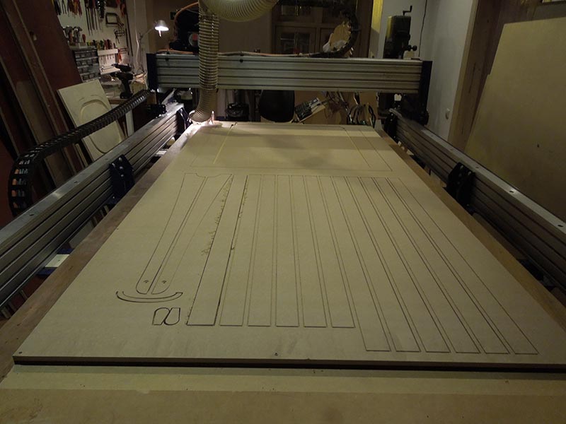
To create a prototype we used a MDF 12mm panel. In about 1.30h we milled the pocket traces (for the arms and the light cable), drilled the holes (so we can hide the light cable) and cutted the profile.
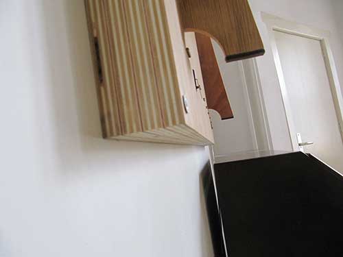
The prototype is still under contrusction and in the meanwhile we are optimizing the design:
- a correct pocket for the switches
- an offset of 0.1mm for the arms pocket (it was necessary to sand the arms to make them fit in)
- a more accurated frame size.
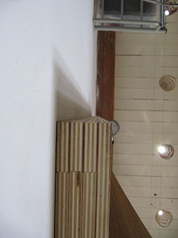
- the MDF is not good for our proposal and once we placed the frame to the wall we could hear and see some cutted of the wood where we have hinges.
Eletronic system
Materials:
- two LED lamps (suppled directlly from 230V)
- 5 meters two wires electric cable.
- two microswitches for high voltage applications.
- two screw connectors.
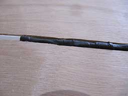
- heat shrink tubing, one long tube..
- two flat red terminals.
Tools:
- Solder station
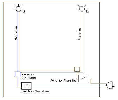
Circuit:
Step-by-steps:
1) Cut the lamp cable from the lamp side and solder the lamp to half of the electrical cable.
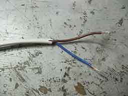
2)Following the length of the image, open and cut the electrical cabless of the two lamps. 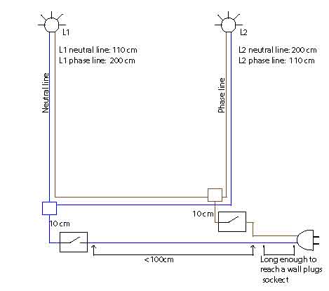
3) Once the arm are attached to the table insert the lamps in their reserved holes on the arms.
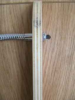
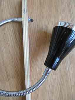
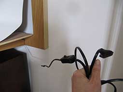
4) Pass the lamp cable from one side to the other of the table.
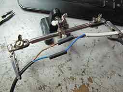
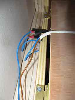
5)Once the table is secured to the frame you can go ahead with the electric system. Join the two brown cables through a screw connector, two wires input / one wire output.
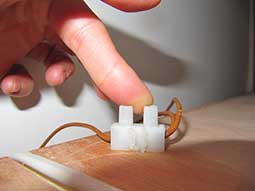
6)With a flat terminator connect the short wire to one side of the microswitch. The other side of the microswitch is the wire that goes to the power plugs.
7)Repeat the steps 3-4-5 with blue wire.
8)Insert the microswitch in the vertical pocket and bend the pads inwards so the table can be properly close.
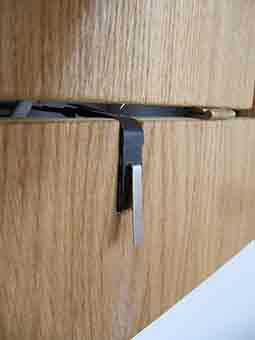
9)Use the hot glue to stuck in the drew connectors in the pocket.
10)Insert all the wires in the long pockets and the electric system is ready.
Errors
1) The table wood direction is upside down respet the frame. Solved in the design
2) The side are so weel straight because we went to a wood shop and we asked to finish the side we a vertical saw machine. To avoid this problem is pay attentio during the glue process. Glued the axis doubly, we glued all the four axis layers at the same time.
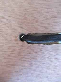
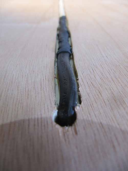
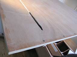
3) We didn't implement in our desing the cable wires in the table. We sloved the problem with a hand millin machine. It solved in the design
Tools
Software: Pathwork.
Machine: Shopbot.