Week8Embedded programming
José J. Lazarte R.

Assignment:
   Read a microcontroller data sheet.
In my case I will use the ATtiny44
Main Features:
8-Bit Microcontroller
Advanced RISC Architecture
- 120 Powerful Instructions and 32 x 8 General Purpose Working Registers.I/O and Packages- Available in 14-Pin SOIC and PDIP
- Twelve Programmable I/O Lines
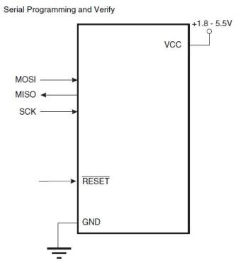
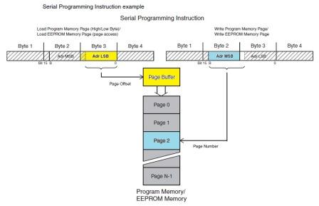
Non-Volatile Program and Data Memories- Program Memory Flash of  2/4/8K Bytes (Endurance: 10,000 Write/Erase Cycles)
 - Programmable EEPROM of 128/256/512 Bytes (Endurance: 100,000 Write/Erase Cycles)
- Internal SRAM of  128/256/512 Bytes (Data Retention: 20 years at 85°C / 100 years at 25°C
- Programming Lock for Self-Programming Flash & EEPROM Data Security)
Special Microcontroller Features- DebugWIRE On-chip Debug System
- In-System Programmable via SPI Port
- Internal and External Interrupt Sources: Pin Change Interrupt on 12 Pins
- Internal Calibrated Oscillator
- On-chip Temperature Sensor
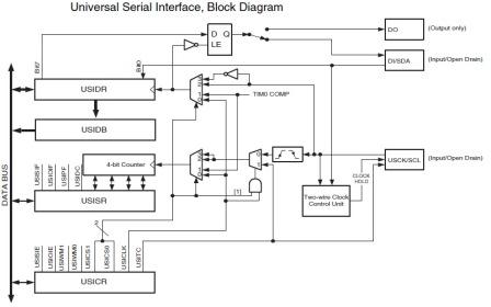
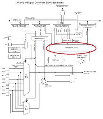
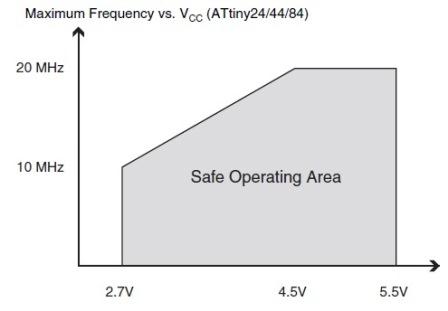
Peripheral Features- One 8-Bit  Timer/Counter with Two PWM Channels
- 10-bit ADC
- Universal Serial Interface
Speed Grade- ATtiny44V
    0 – 4 MHz @ 1.8 – 5.5V

    0 – 10 MHz @ 2.7 – 5.5V
- ATtiny44
    0 – 10 MHz @ 2.7 – 5.5V
    0 – 20 MHz @ 4.5 – 5.5V
Operating Voltage: 1.8 – 5.5V for ATtiny44V
2.7 – 5.5V for ATtiny44
Industrial Temperature Range: -40°C to +85°C
Low Power Consumption
- Active Mode (1 MHz System Clock): 300 μA @ 1.8V
- Power-Down Mode: 0.1 μA @ 1.8V

The AVR architecture has  two main memory spaces, the Data memory and the Program memory space. In addition, the ATtiny44 has features like an EEPROM Memory for data storage. All three memory spaces are linear and regular.
Figure represents the principal clock systems in the AVR and their distribution. All of the clocks does not need to be active at a given time. In order to reduce power consumption, the clocks to modules not being used can be halted by using different sleep modes.

XTAL1 and XTAL2 are input and output, respectively, of an inverting amplifier which can be configured to be used as an On-chip Oscillator, as shown in Figure, Either a quartz crystal or a
ceramic resonator may be used.

The direction of one port pin can be changed without unintentionally changing the direction of any other pin with the SBI and CBI instructions. The same applies when changing drive value (if configured as output) or enabling/disabling of pull-up resistors (if configured as input). Each output buffer has symmetrical drive characteristics with both high sink and source capability. The driver pin is strong enough to drive LED displays directly. All port pins have individually selectable pull-up resistors with a supply-voltage invariant resistance. All I/O pins have protection diodes to both VCC and Ground. The ports are bi-directional I/O ports with optional internal pull-ups. Figure shows a functional description of one I/O-port pin, here generically called Pxn.

The Universal Serial Interface (USI), provides the basic hardware resources needed for serial communication. Combined with a minimum of control software, the USI allows significantly higher transfer rates and uses less code space than solutions based on software only. Interrupts are included to minimize the processor load.
A simplified block diagram of the USI is shown in figure.

The ATtiny44 features a 10-bit successive approximation ADC. The ADC is connected to 8-pin port A for external sources. In addition to external sources internal temperature sensor can be measured by ADC. Analog Multiplexer allows eight single-ended channels or 12 differential channels from Port A.
The programmable gain stage provides ampification steps 0 dB (1x) and 
26 dB (20x) 
for 12 differential ADC channels.
The ADC contains a Sample and Hold circuit which ensures that the input voltage to the ADC is held at a constant level during conversion.
Internal reference voltage of nominally 1.1V is provided On-chip. Alternatively, VCC can be used as reference voltage for single ended channels. There is also an option to use an external voltage reference and turn-off the internal voltage reference.

Serial Programming: Both the Flash and EEPROM memory arrays can be programmed using the serial SPI bus while RESET is pulled to GND. The serial interface consists of pins SCK, MOSI (input) and MISO (output).
The maximum operating frequency of the device depends on VCC. As shown in Figure, the maximum frequency vs. VCC relationship is linear between 1.8V < VCC < 2.7V and between 2.7V < VCC < 4.5V.

Program your board to do something,
With the ATtiny44 microcontroller, we have implemented a board that has an LED and a button. To make the programming process I will use the USB programmer that was implemented in Assignment 4.
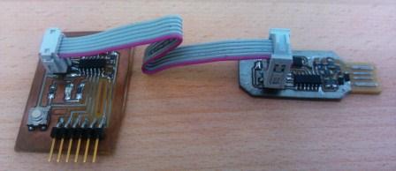
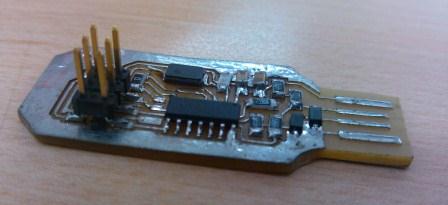
FabISP in-circuit programmer: Assignment 4 Electronics production
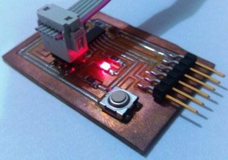
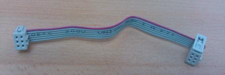
To connect the controller using the ISP (J1) terminal to the board microcontroller, I built a connection cable, (I had to be very careful on identifying the terminals in order to avoid malfunctions).
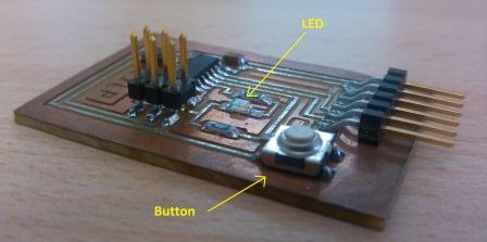
Echo hello-world board,: Assignment 6 Electronics design
Interconnect the two boards, and it is ready to connect to the USB port of the computer

First we prepare the computer with the right software to do the programming procedure, in my case I will use the Arduino platform to program the  microcontroller.
1. Get the arduino program Download and install Arduino Software Version 1.03 or newer.
2. Get ATtiny microcontroller driver  Download the ATtiny Master.zip
3. Unzip the attiny master.zip file.It should contain an “attiny-master” folder that contains an “attiny” folder.
4. Copy the folder "attiny"Copy the “attiny” folder from the unzipped ATtiny master.zip to the “hardware” folder inside the Arduino Folder. That contains the file boards.txt and another folder called variants.
Then prepare the USB port to recognize the controller.
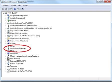
1. Get the Driver usbtinyisp_libusb-win32_1.2.1.0   To use  USBTinyISP with the 64-bit versions of Windows 7 or Vista 
2. Install the DriverThere is still a warning that “Windows can’t verify the publisher of this driver software” but there are no more errors about digital signatures and the new drivers appear to install and work correctly
After installing the driver, to connect the programmer you should be able to appreciate the confirmation of recognition of the hardware, as shown in the following figure.

When the software and hardware are ready in the computer, connect the programer to the USB port and load the Arduino program to perform the following settings.
First we need to set the type of microcontroller used.
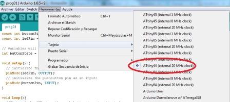
Second we define the com port used by the programmer.
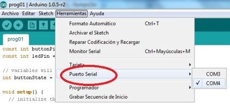
Third, we must select the type of programmer:
"USBtinyISP"
To make the programming process will use a program to interact with the button and the LED.
// set pin numbers:
const int buttonPin = 2;     // the number of the pushbutton pin
const int ledPin =  3;      // the number of the LED pin
// variables will change:
int buttonState = 0;         // variable for reading the pushbutton status
void setup() {
  // initialize the LED pin as an output:
  pinMode(ledPin, OUTPUT);     
  // initialize the pushbutton pin as an input:
  pinMode(buttonPin, INPUT);    
}
void loop(){   
  // read the state of the pushbutton value:
  buttonState = digitalRead(buttonPin);
  // check if the pushbutton is pressed.
  if (buttonState == HIGH) {    
    // turn LED on:   
  digitalWrite(ledPin, HIGH);   // turn the LED on (HIGH is the voltage level)
  delay(5);               // wait for a second
  digitalWrite(ledPin, LOW);    // turn the LED off by making the voltage LOW
  delay(5);               // wait for a second
  }
  else {
  digitalWrite(ledPin, HIGH);   // turn the LED on (HIGH is the voltage level)
  delay(50);               // wait for a second
  digitalWrite(ledPin, LOW);    // turn the LED off by making the voltage LOW
  delay(50);               // wait for a second
  }
}
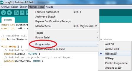
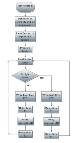
The program structure is shown in the following flowchart.The program in Arduino 
Click over the figure to see the video
.....with as many different programming languages
      and programming environments as possible........
seeking alternatives that allow me to work in other environments and languages​​, I found a way to program that is being used in many environments, their name are MODKIT and ARDUBLOCK.  Both  MODKIT and ARDUBLOCK are very intuitive and easy to use. And the best is that you can interact right through the Arduino platform
Then I show you how to set ARDUBLOCK to work with the ATtiny44 using Arduino.
1. Download ardublock-all.jarDownload link: http://cloud.github.com/downloads/taweili/ardublock/ardublock-all.jar
2. Location of the downloaded fileInclude all.jar ardublock-file in the tools folder of the Arduino IDE ".... / arduino-1.0.1/tools/ArduBlockTool/tool/ardublock-all.jar"
You must create folders:
/ArduBlockTool / tool /
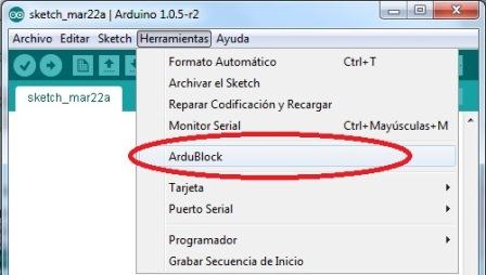
3. After installing and open the Arduino IDE  in the "Tools" menu you can find the link to Ardublock
Using the flow chart shown above, the program is performed in ARDUBLOCK, then translated into Arduino and program the ATtiny44. I can download it directly from the ARDUBLOCK environment too.
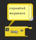
To start programming charge a loop block.
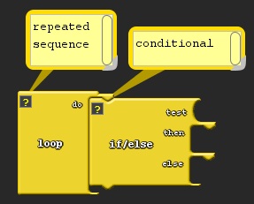
We link to the previous block to the block conditional "IF", which has an active input condition, when the input is true (in   in this case reading the input pin 3), the block performs the action in the part "then", if the result is false the block performs the action in the part "else".
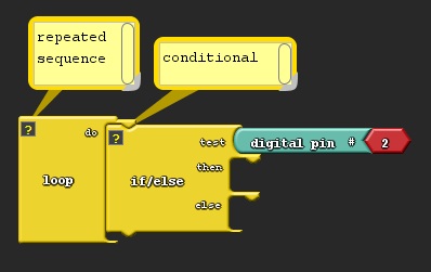
Input 3 gives the initial condition.
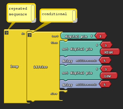
If the condition is true, it performs the power on and power off  of la LED with a time delay of 5 milliseconds.
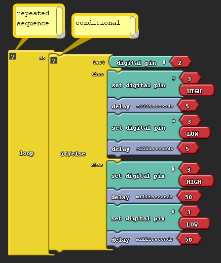
If the condition is false, it performs the power on and power off  of la LED with a time delay of 50 milliseconds.
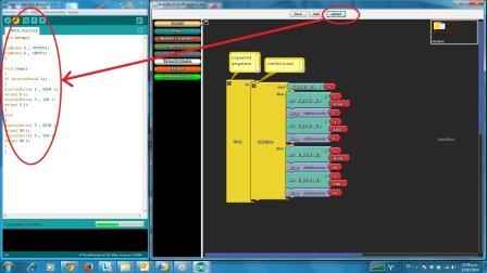
To download the code to the ATtiny44 I used the button "upload" which translates the graph code to the Arduino code.
Click over the figure to see the video
References:
                    http://solorobotica.blogspot.com/2012/08/ardublock-entorno-de-programacion.html
                    http://www.smartdraw.com/downloads/
                    http://blog.modk.it/2012/12/happy-holidays-modkit-micro-open-for-all.html
                    http://ingenieroaburrido.com/convertir-tu-arduino-en-un-programador-isp
                    http://highlowtech.org/?p=1695