

Below is a video of the hand working
(Click this link if embedded video is not working)
I wanted a project that would help me learn about living hinges. I'm already making a robotic hand that uses mechanical linkages for a project my company is working on, but I really wanted to try something different. I haven't seen anyone use living hinges as fingers yet either, so I wanted to see how it could be done.
You can download all the design
files for this project here.
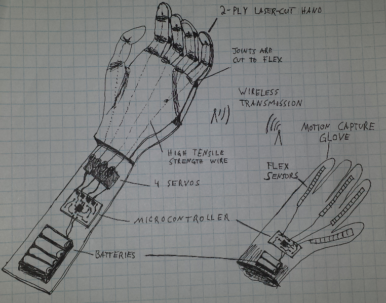
For my final project, I wanted to make a robotic hand that would be able to mimic my movements. I sketched the design up in Sketchup on one of the first weeks of the FabAcademy class. This project will include input devices, output devices, various CAD softwares (Sketchup, inkscape, openSCAD, and EagleCAD). It will involve milling PCBs, laser cutting, 3d printing, soldering and programming.
I then drewthis design ink inkscape and laser cut it in cardboard as a test. I changed the types of living hinge because the Sketchup deign just used straight lines. This did not go according to plan because the living hinge cuts were too close together for the cardboard to efficiently dissipate all the heat. It ended up catching on fire and burning up off of the fingers. Luckily I was able to test with the other fingers. Testing this design proved that a lot more work needed to be done on the living hinges.
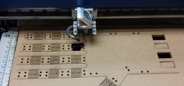
Out of the literal ashes of the first design, the next iteration started in the mechanism week. For the mechanism I designed, I focused on a single finger. I learned about designing a better living hinge and designed a few prototypes to test with. As I mention in my "mechanisms" week page, I cut some examples to play with before redesigning the finger. I found that for a successful 180 bend, I would have to use a thin material (1/16") and I would have to scale up the width of my fingers to allow the straight parts of the living hinge to rotate fully. I also needed to drastically increase the length of my hinge-to-finger length ratio.
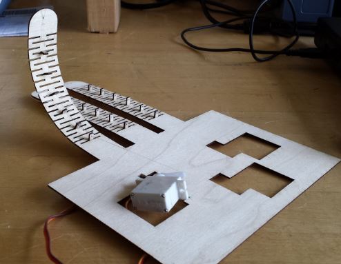
I started with a single finger using a living hinge along its entire length. I tied some really thin wire through the finger in a loop and tested it. I found that I could get the bend I wanted, however, the wire would get in the way of the finger actually closing around an object. To fix this, I cut some excess plastic from one of the reels of electronics components and stuck them into the slots on the living hinge and threaded the wire through them. This allowed the wire to pull tight, but held the wire close to the finger.
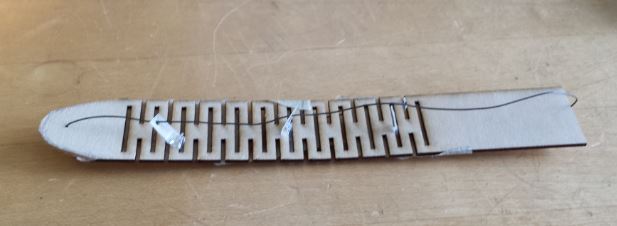
I had assumed I could turn my servos 90 degrees to allow to have a powered pull in both directions of the finger, making it overall stronger when the finger opens as well as closes. Laying the servo on its allowed me to tie one end of the wire to each side of a servo horn. I cut a new iteration of the design to test this concept out. This time I used fishing line and laser cut some spacers for the line to pass through to hold it close to the finger.
The sideways servo idea didn't work well. There's no really good was to securely attach the servo in place. This also takes up MUCH more space than the first design. On the bright side, I tested the servo with the fishing line on the finger and it works exactly as I had planned!
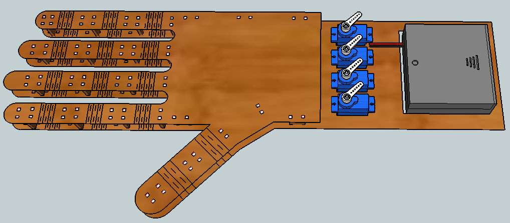
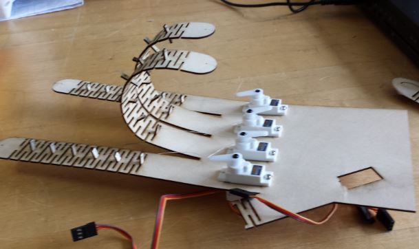
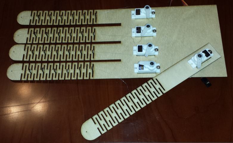
This design went back to my original concept as far as the servo layout was concerned. This allowed me to put all 5 servos in place. I didn't really need the fingers to be powered to open. If I move the servo to release tension on the finger, it springs back to lay flat with the palm. I ran into a pretty big issue though. The thumb was cut at an angle from all the other fingers. When I actuated it, it bent away from the center of the hand. I found this was due to the wood grain on the top and bottom sides of the plywood. When testing, I actually broke the thumb off completely! @_@ On my next test, I will cut the thumb separately, and align it such that the wood grain helps the thumb bend straight. I will then attach it to the palm at the angle I want it to be.
I cut the thumb separately and attached it to the palm. I tied the fingers up as with my previous design. All works well... Now on to the electronics.
Originally, I had wanted to try to do wireless communication of some type to connect a glove with sensors to the hand. This was a lot of extra work that I didn't really have time for. Taking the advice of Neil after sharing one day during class, I went with just using a wired interface instead.
As for the glove, I had already been working on a similar glove project and decided to use my findings from that here. I made my own flex sensors from scratch out of conductive plastic, conductive thread, and tape. The sensors all have slightly different values of resistance, but they are scalable in the code, so I won't have any worries that I will get it working.
Here's how those sensors are made. First I stretch out two pieces of Gaffers tape (masking tape works well too) and lay them face up on a table. It helps to tack down the ends so it doesn't move. Then I use a couple of feet of conductive thread and make a loop in one end. My thread has a really high resistance, so that's why I am looping it. Lay the loops in the middle of each stick side of tape as shown below:
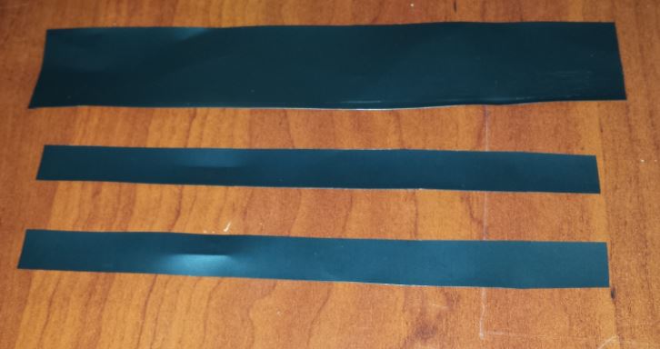
Then cut 3 strips of conductive plastic from a conductive bag. Two of these pieces should be thinner than the remaining one. Cut the two thin pieces about 0.5" shorter than the thicker one.
Put the thin pieces of conductive plastic on top of the thread on the tape making sure to cover the loose end of the thread. at the other end of the thread, move it at a 45 degree bend to the edge of the tape. This will help prevent the two pieces of thread (one from each side of the tape) from shorting int he final sensor.
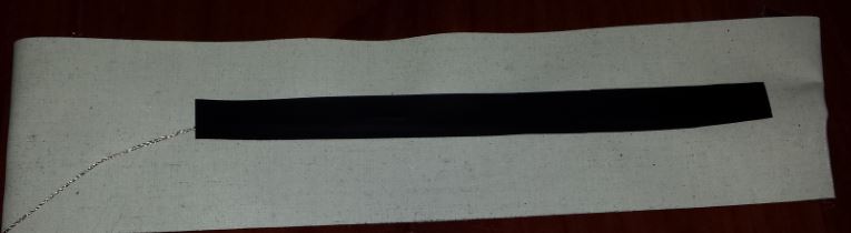
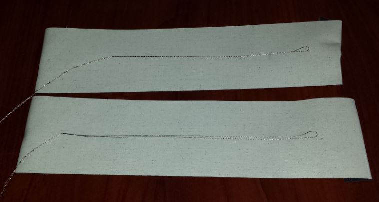
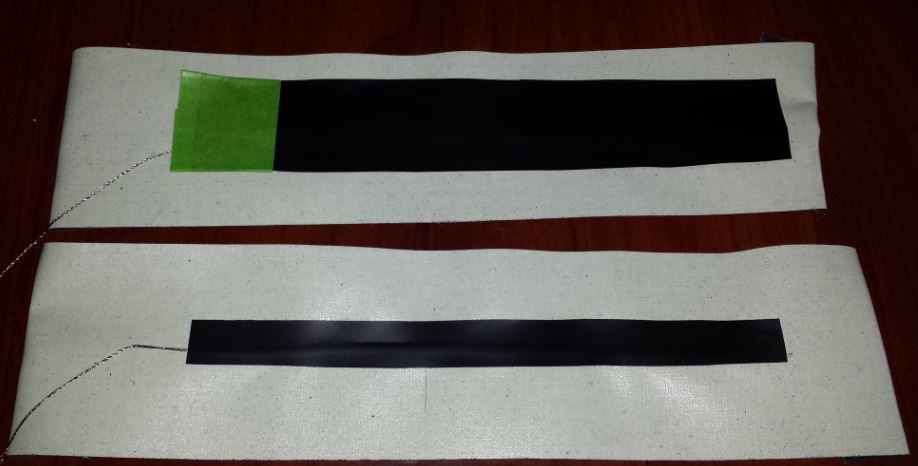
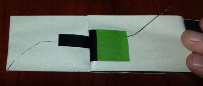
Now wrap masking tape (or other non-conductive tape) around one end of the thicker piece of conductive plastic as shown and lay it on one piece of tape such that it entirely covers the thinner piece of plastic.
Match up the two sides of tape and the flexible sensor is finished.
In my case, the sensor has a resistance of about 1k-ohms when straight and about 300-ohms when bent. These sensors are not very good at detecting minute angles, but they will do well for approximating the finger bends. I experimented with multiple ways of making a glove and all failed. I've never had an aptitude for sewing or anything like that (believe me, I have many failed projects in the past... it is like some people are just not made for doing some things.... I'm no tailor.) Below are some pics from a couple of different methods I saw online for making gloves.... I wasted several hours trying them each several times to no avail.
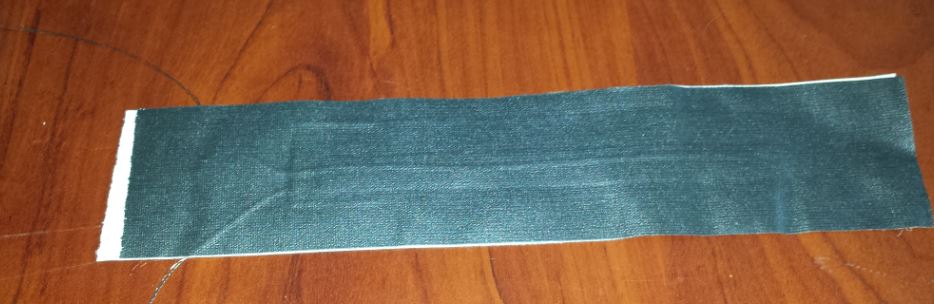
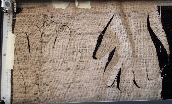
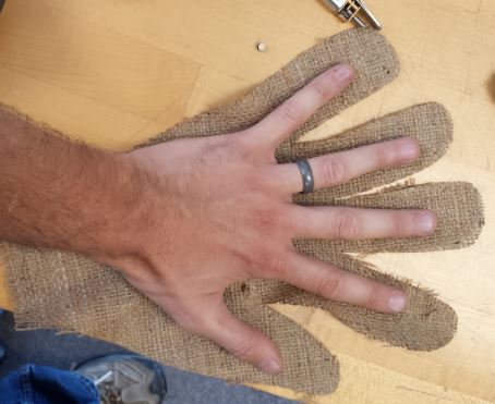
The first was from this site which basically uses a larger outline of a hand cut out in two sheets of fabric, then gluing the two together and turning it inside-out to make a nice glove... I drew mine in Inkscape and laser cut the design in burlap. I did this twice and got it wrong both times. I learned that to cut fabric in the laser cutter, you must increase the frequency quite a bit (to cut through all the threads) and watch for fires. After those two failed attempts, I just traced my hand and cut it out by hand. This also failed. So I moved on to a different method.
The second method of making a glove
pattern was more involved and came
from this instructable. Basically, you wrap your hand with
tape, then cut the tape off and that is your pattern. Again, I did
this, took a picture of the pattern, imported this picture into
inkscape and traced the outline leaving a bit of a margin around
everything to allow for glue and then cut it out on the laser
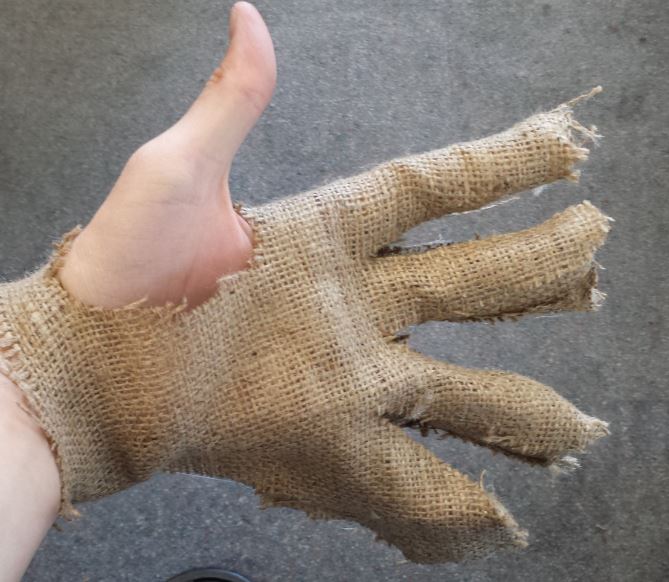
cutter. This method was much closer to a success, but it turned
out to be something tat looks like a horror movie prop. Also, you
get a lot of funny looks when you are wrapping your hand in tape in
the fablab....
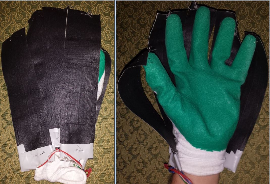
So after wasting a lot of time, I decided it was in my best interest to buy a glove since making one from scratch really isn't the point of my project. I picked up a pair of gloves from a local dollar store. Opportunity costs are important!
I attached the flexible sensors to the store-bought glove by sewing the ends to the glove in such a way as not to bend the sensor when my hand was relaxed. This was tricky because the sensors themselves are wide and overlap quite a bit. This can cause them to physically interfere with one anothers' motion. I had attempted to sew each flex sensor to the glove along its entire length, but this stressed the sensor, reducing the range of possible resistances. The sensors also limited the motion of my fingers in the glove. If I mounted them when my finger was straight, the sensors prevented my fingers from bending. If I mounted them with my finger bent, then when I straightened my finger the flex sensor would crumple in several places. Both situations lead to an incorrect representation of the finger's position. The best way to mount them was found to be to sew them to the glove only on the top and bottom edges of the sensor. This looks like a quite strange baseball glove, but it works very well.
Since I need 5 analog inputs and 5 servo outputs, that limits me to the processors I can use to do this easily. There are 9 I/O pins accessible on an AtTiny44, which would mean I'd have to remove one finger somehow. I considered tying the value of the pinky and ring finger together since in a human hand those fingers don't move completely independently. You can reprogram the fuses on the Attiny44 to use the reset pin as a digital I/O, however then you'd have to program it using the high voltage method on the AVRDragon. After testing all of this out on the Attiny44, using the arduino IDE it was shown that the AtTiny44 did not have enough memory for all of the fingers of the glove and servo mappings. I started experimenting with the AtTinyby using the general purpose I/O board I made in inputs week instead of wasting time making a new custom board in case it didn't work out.
I then redesigned a FabLeo board with extra resistors that I can use to connect to the flex sensors in a voltage divider on the analog inputs. I was able to successfully get all of the code to fit in the memory (of course...).
The code itself is relatively simple. I read in an analog input, map it to servo movements, then send it out the servo pin, respective of which finger it is. I also have the outputs streaming out serially when debugging. I used the Arduino IDE. Mainly because I like the serial programming of the FabLeo board. The servo library is useful, but I modified the servo library, especially for future use of LEO-based boards I will be making. For the AtMega32U4 chip, in the servo libs header file, both instances of "_timer1" must be changed to "_timer3" in the following lines:
#elif defined(__AVR_ATmega32U4__)
#define _useTimer1
typedef enum { _timer1, _Nbr_16timers } timer16_Sequence_t ;
It might well have worked without this change, but I had previously tried using a Pololu AStar which is a Leonardo Clone, and it did not handle the timing of servos correctly at all and I figured changing which timer it used might help.
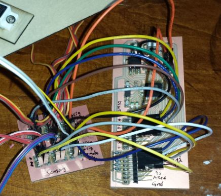
I modified the FabLeo design slightly to include a resistor on each analog input. This way I can solder in a good resistor value as part of a voltage divider for the flex sensors. Since I expect to use this board for other projects in the future, I didn't want to limit myself by putting all of the servo and flex sensor pins on the board. I designed a simple daughterboard to hold this mess of wires.
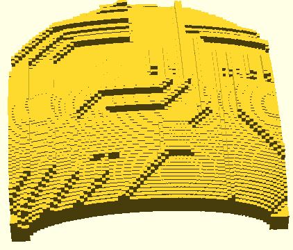
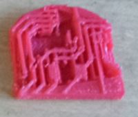
I wanted to add a 3d printing element to this project. I chose to add fingerprints that look like circuitry. To do this, I found a really helpful script someone wrote in OpenSCAD that stretches an image over a dome. I took the schematic of the FabLeo I modified and took a small section of it that looked complicated. Then I used the online tool from Makerbot to convert the PNG to an array, and pasted this array into the openSCAD script. The preview looked very good! but it never fully renders. I tried it on multiple versions of OpenSCAD pn windows and linux to no avail.
The image I used:

I ended up finding a java-based app that converts a PNG heightmap directly to STL format. I used this and got the STL output in literally 6 seconds (as opposed to the several hours I spent debugging the openSCAD problems).
The resulting 3D print is shown below. I had to clean it up a little with a razor knife as the java app produced a completely square design. I believe this is because the maker of that app wanted to ensure that there would be a raft for every design, regardless of what software or machine was used to print it.
I decided that if I had enough time I'd mold silicone fingerprints as well. You can see the progress on the Molding and Casting page as well as.
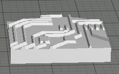
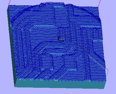
The resulting toolpaths from importing the STL file into Partworks3D can be seen below. I used a 1/32" flat endmill (the same one as I used to mill my PCB outlines):
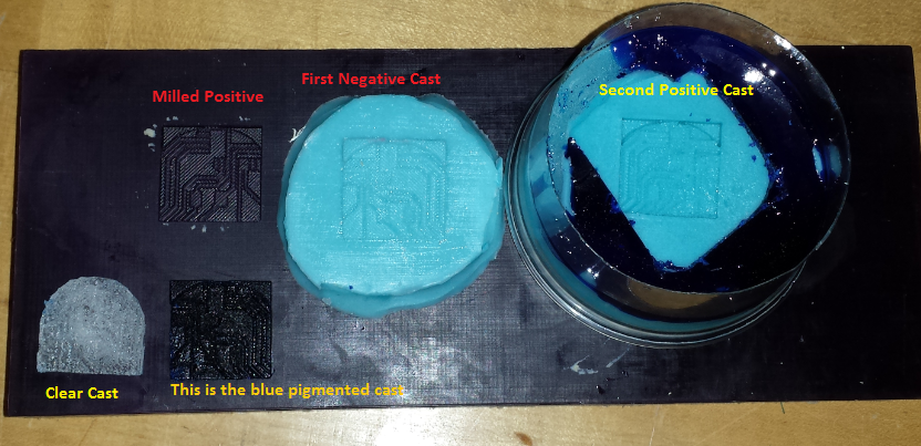
It was at this point the I realized that I carved out the positive of the mold when I wanted the negative. This isn't a big problem as I can just make multiple casts. So I cast a negative out of Mold Star 16 which cures in 30 minutes. Once this one cured, I LOADED it with mold release and then cast a positive silicone mold. This came out pretty well and I realized that I overused the mold release. The mold release caused a loss in detail in the new positive. (The negative is on the left, positive on the right.)

I then decided to play with some of the urethane materials I had in the lab to learn how to work with them some. I started with Smoothcast 365 which is an awesome product! It is practically clear in its natural form, very thin liquid so it fills in all the tiny details of the mold, and hardens in 10 minutes! I didn't notice any large amount of fumes or stink the mixture produced either. It was awesome to work with. I think these two products are "go to" products unless I need something else more specifically. Oh, and I forgot to mention SmoothCast 365 is designed to use pigments as well. I put an incredibly tiny amount of blue pigment in on my second cast of this stuff and I found out just how concentrated the pigment is...
The final hand works well! You can check out the video below, but basically, the living hinge hand mimics my finger positions in near real time. I was able to pick up a small box (filled with wires and various breakout boards) with the hand.
I designed and fabricated a custom board for the project.
I designed and fabricated a living hinge hand that I cut on the laser cutter.
I designed and fabricated flexible sensors that cost only pennies.
I designed and fabricated 3D prints and molded fingerprints to to aid in gripping objects.
I came up with a plan to release the I.P. under GPL2 license.
I came up with a future plan for dissemination of the project as a kit to be used in workshops and summer camps.
Remaining tasks include improvement of the design of course. Following the spiral development pattern, there are always improvements that can be made (specifics are mentioned in the answer to the next question).
The living hinge worked very well for my project. I get a really good range of motion from each finger. The things that don't work so well are my failed attempts to make a glove from scratch, and I wish there was a better way to mount the flex sensors to the glove.
How can I make the flex sensors smaller?
How can I mount the flex sensors better? (Right now the glove doesn't look like a production product.)
Where can I secure better gloves for the project if I were to do this as a kit in a workshop?
I have learned an enormous amount! Of course I've learned how to use each machine, technique, and process in the fab academy curriculum, but more specifically, I've found a very good workflow and toolpath for making product designs quickly and efficiently; sorting out techniques that I feel work well for me in general and those that do not based on the type of project I will be working on. I've also learned to think more globally about my designs. They aren't just projects for me to do, but I need to start thinking more about how they can affect or inspire others. I will certainly keep better track of my projects and post them online for others to see in the hopes that I might help someone else.
I am releasing all the hardware and software under GPL2 license.
Originally, I set out my evaluation criteria as follows.
Below is a video of the hand working
(Click this link if embedded video is not working)
Web template design: davereederdesign.com