

week 8.
This week's assignement was to...
Programm the LED + BUTTON BOARD
Necessary material:
- FTDI cable
- USB-MiniUSB cable
- FabISP programmer
- LED+Button Board
Software:
- ARduino IDE software
- Attiny board files
- FTDi Drivers
Attiny specs
Since that's the microcontroller in the board, one should read its specsheet in order to get an idea on how it works. it's a rather complex theme for a newbie like me, so it will take me some more reading and research to get to know this microprocessor ..... here are the specsheets:
Overview (+-20 pages) - http://www.atmel.com/Images/8183S.pdf
Full specsheets (+-200 pages) - http://www.atmel.com/Images/doc8183.pdf
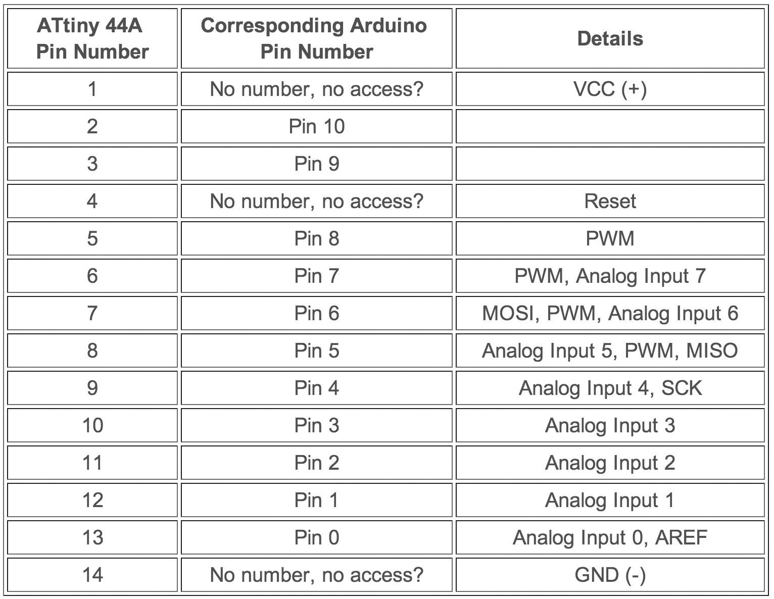
ATtiny 44A vs. Arduino Pin-Out Numbering:
Attiny and arduino have diferrent numbering for its pin-outs, so you have to know the corresponding numbers in order to work with the Arduino IDE.

1. - Installing ATtiny support in Arduino (so the Arduino IDE can talk to the ATtiny44A)
- Download and install the board files (download here: http://academy.cba.mit.edu/content/tutorials/akf/Downloads/attiny.zip)
- Unzip.
- Locate your Arduino sketchbook folder:
- In the Arduino software > "Arduino" menu > preferences
- Navigate to your "sketchbook" folder.
- Create a new sub-folder called "hardware" in the "sketchbook" folder.
- Copy the "attiny" folder extracted from the zip archive to the "hardware" folder.
- Restart the Arduino IDE
- You should see ATtiny entries in the Tools > Board menu.
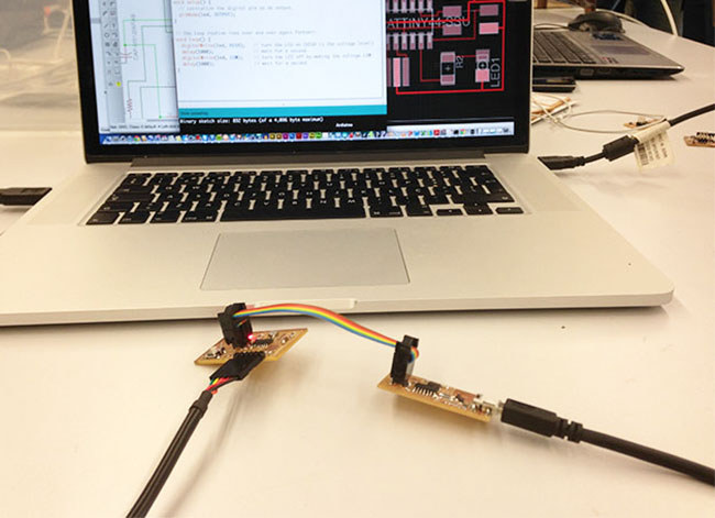
2. - Connect and power the boards
- Both boards must be connected to power. The FabISP gets power through the USB cable and the hello board uses the FTDI cable for the purpose.
- Now connect both boards with the flatband cable made in
week 4
IMPORTANT NOTE: when connecting the FabISP and the Hello Board, remember to match GND (ground) in both ends of the cable
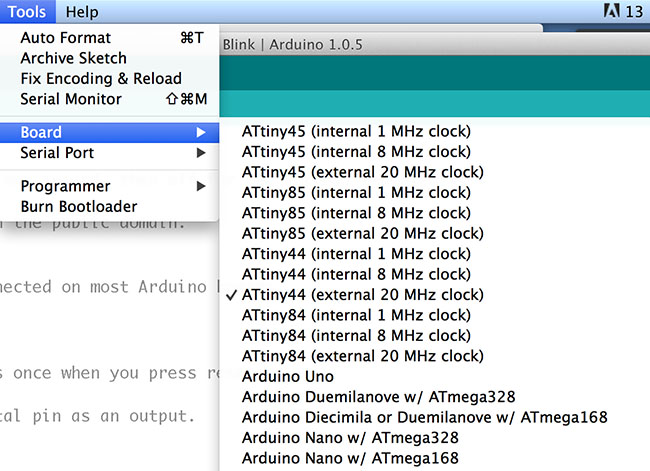
3. - Configuring the ATtiny to run at 20 MHz
- By default, the ATtiny runs at 1 MHz (the setting used by the unmodified "ATtiny44)
- There's an extra step to configure the microcontroller to run at 20 MHz – as we have an external 20 MHZ resonator on the Hello Button + LED board.
- Select the "ATtiny44 (external 20 MHz clock)" from the Boards menu.
4. - Select Programmer
- Select the appropriate item from the Tools > Board menu (leave the serial port set to that of your Arduino board).
- Select the appropriate item from the Tools > Programmer menu > USBtinyISP.
5. - Burn Bootloader
Run the "Burn Bootloader" command from the Tools menu.
(NOTE: Bootloader is a piece of code that runs before any operating system is running.
Bootloader are used to boot other operating systems, usually each operating system has a set of bootloaders specific for it.)
This stage of the process didn't go well, i kept getting error messages, telling me the software couldn´t find the FabISP.
After some trys we discover that my FabISP wasn't working, for a reason yet to be discovered, so i used my fellow faber Delio's FabISP to program my Hello Board.
In the next days i will try to reprogram the FabISP to see if i can put it to work.
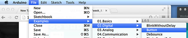
6. - PROGRAM THE BOARD
Now it was time to program the Hello Button + LED board, making use and controlling the button and the led.
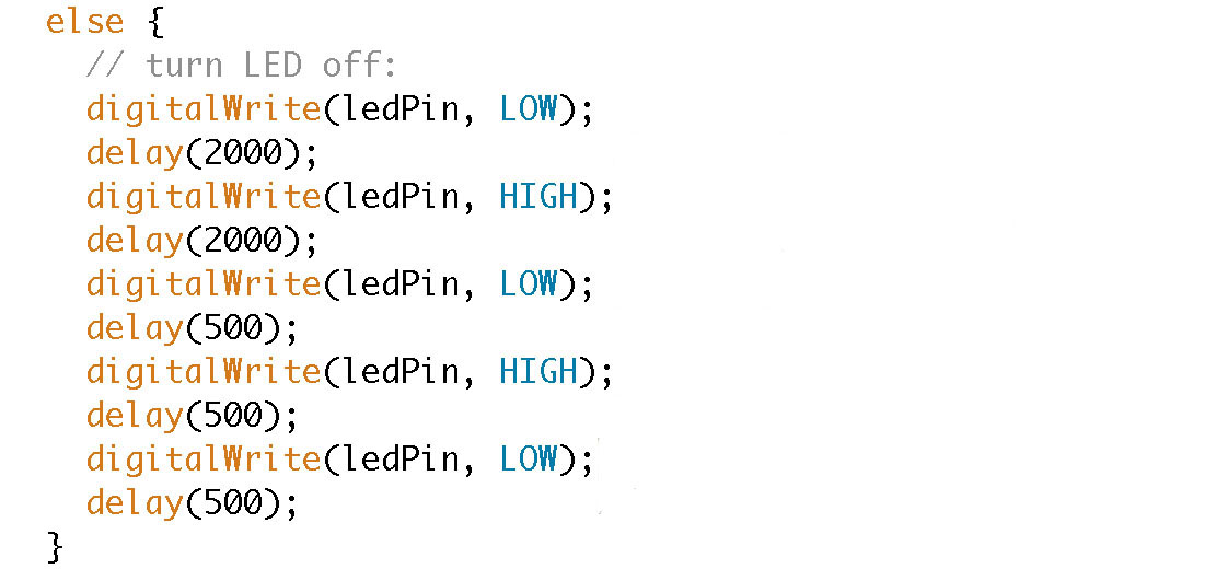
The Arduino IDE comes with some program examples, and i chose BUTTON for changing the code (File > Examples > 02.Digital > Button)
I changed the code to modify the ryhtm of the blinking, by adding instructions and varying on delay times.
7. - Upload the modified code to the Hello Led + Button board
Here is the result and the proof that the board was tammed!!! :)))
You can download the design files here