
Activity Log
3 June
Last day before presenting. Time to fit everything in the box and prepare the actual presentation. I used lots of cable ties to make some order and pass cables through the vase and to the bottom in the box, not very clean but doesn't interfere with the pan tilt movement.
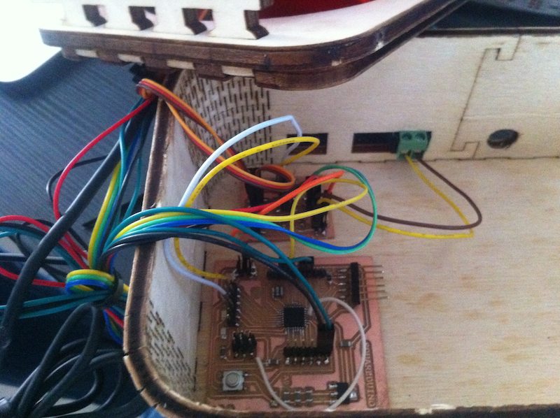
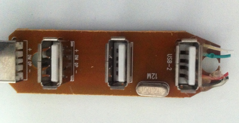
Apart from the Raspberry I also did fit in the box an old USB hub which had some bad connections, and redid it to add support for Wifi dongle.
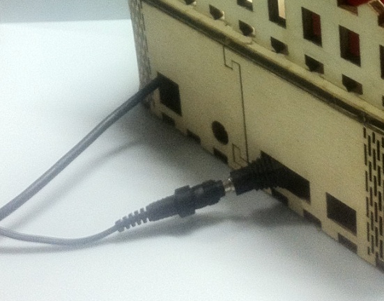
I also planned some holes on the back of the box to run cables for power and ethernet:
Finally I quickly tested the demo script I wrote for the presentation, and made a small video just in case something would brake at the last minute. Everything works, so I'd better stop and wait for tomorrow. It has been a long jurney till here, but I'm very happy of the result.
I'll spend the rest of the day making some vynil stickers to decorate PACO and completing some reports for classes I didn't finish yet.
2 June
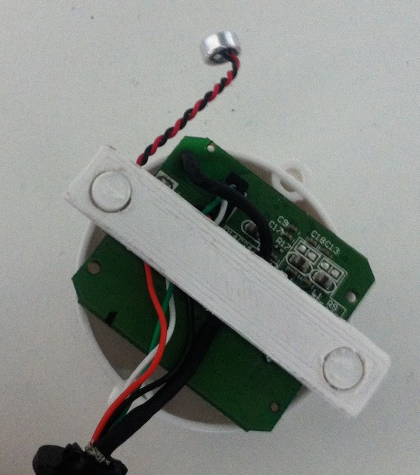
Today is national holiday, everybody is on the beach, but I better keep working as in two days I have to present the project. Yesterday I worked on the software API on the Raspberry, hoping everything will integrate well. The pan-tilt mechanism works and I just neet to put everything in the box and make it look pretty for the presentation.
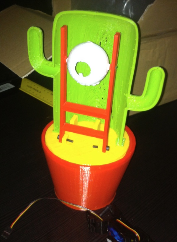
I replaced the wire with the fishing line and the tilt mechanism is finished:
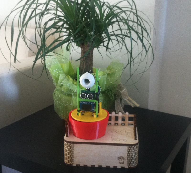
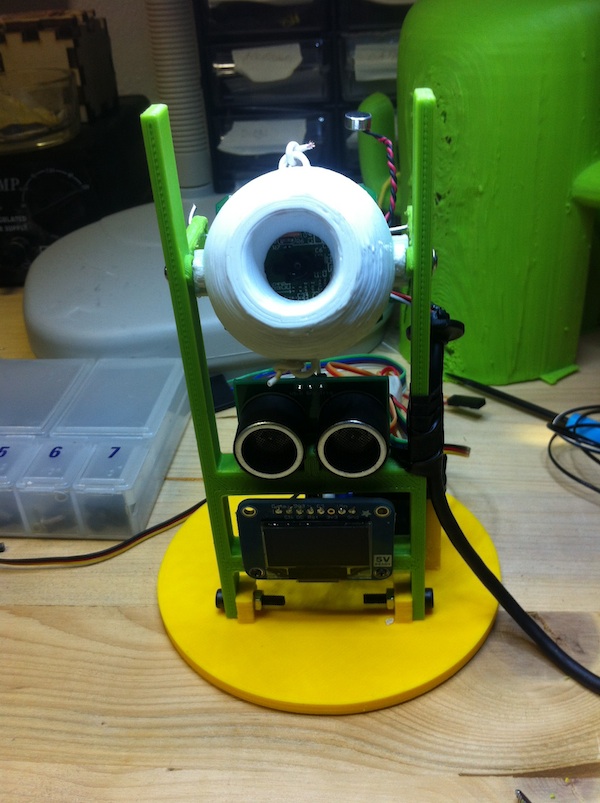
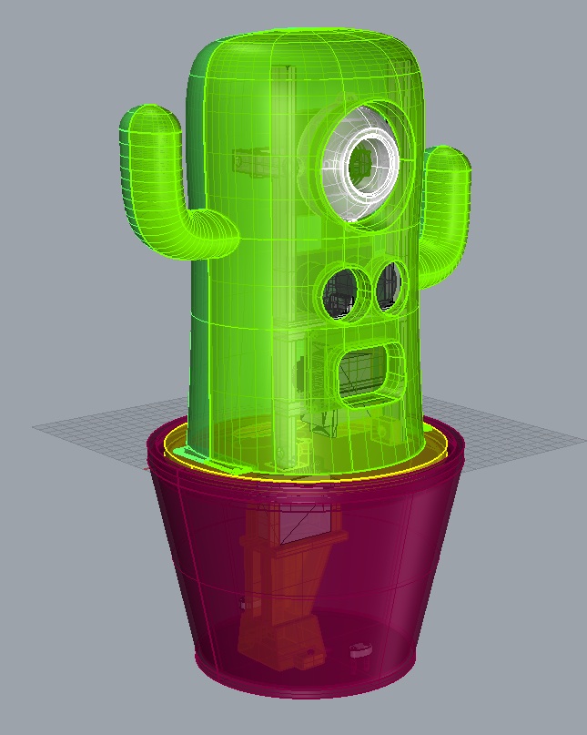
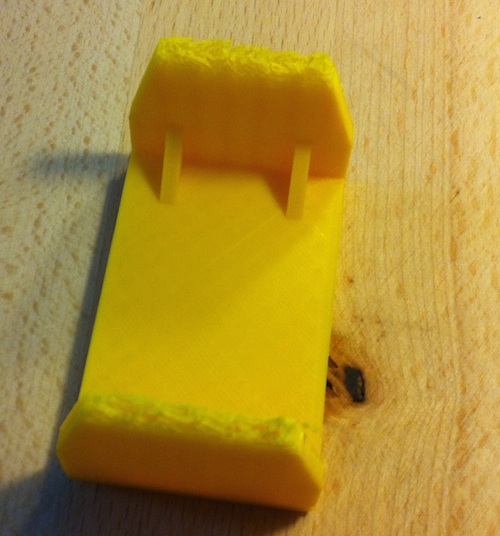
Putting PACO in the finished box for the first time made me confident I'm almost there:
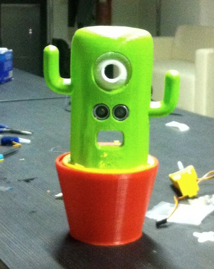
Something you can notice is that the ultrasonic sensor is mounted in the back rather that in the front. I later needed to move it forward as it was not popping out the case enough and was not working.
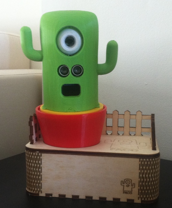
The project looks almost finished, but till it's not moving, talking, smiling etc, it's not! At least I could take a picture for the project slide I need to upload.
30 May 2014
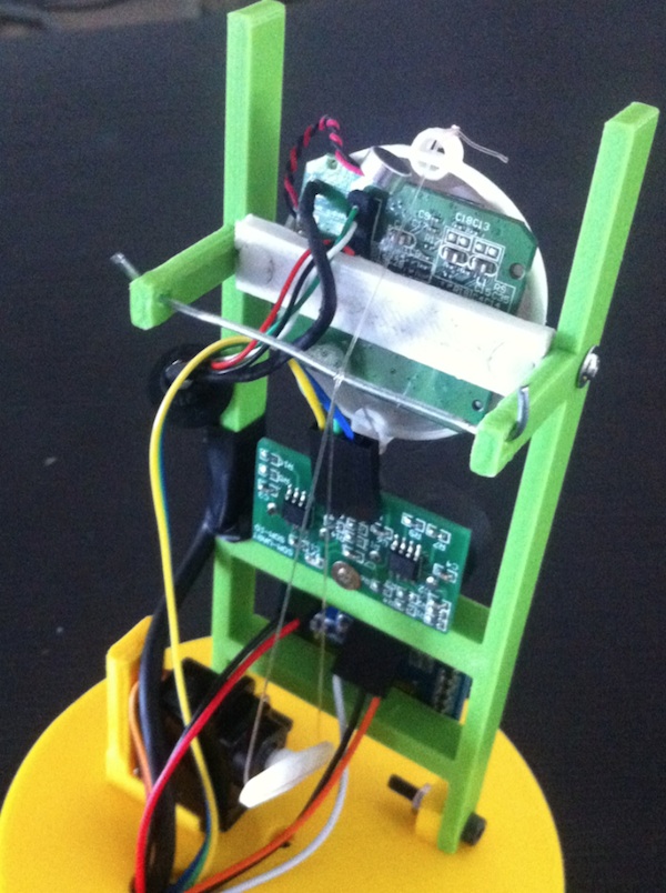
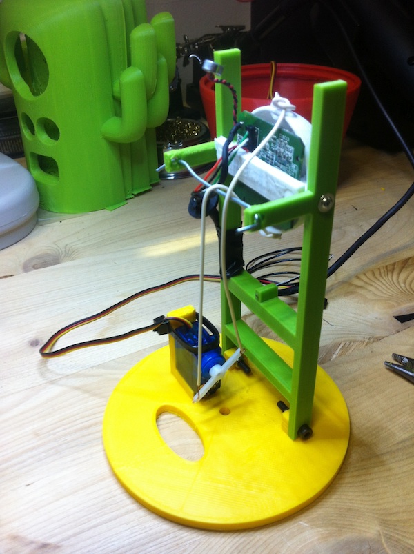
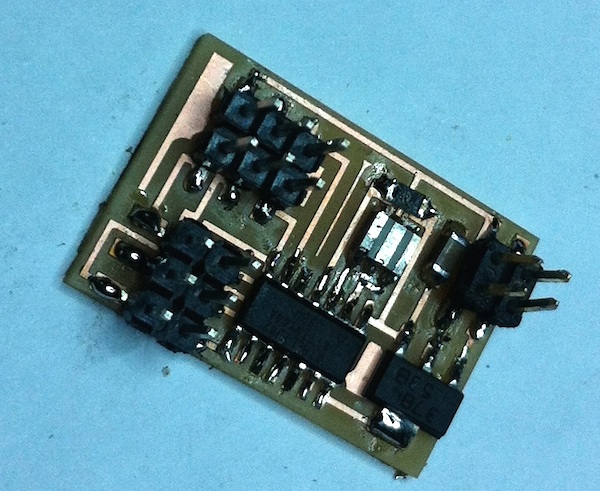
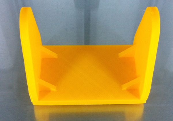
Time for adding the electronics and start testing everything together:
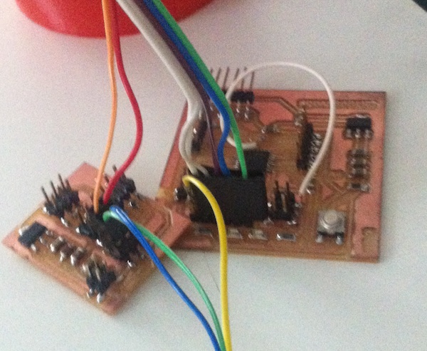
I'm making small pin connectors and trying to respect some kind of color coding to distinguish power from signals in sensors. In general I'm using the standard red-black for power and ground, other colors for signals. But I don't have enough red-black cable so I'm taking pictures and double checking connections to make sure not to burn anything.

I also started working on the wooden lasercut box for holding the Raspberry and the boards. It looks cool, but there's much work to do before finishing. I had problems with cutting it as I discovered plywood panels from the same brand, size and make, have different density and some would not cut properly with the same settings. I'll be increasing power to 50% (speed 100%) on the 90W laser to have it cut properly from now on.
29 May 2014
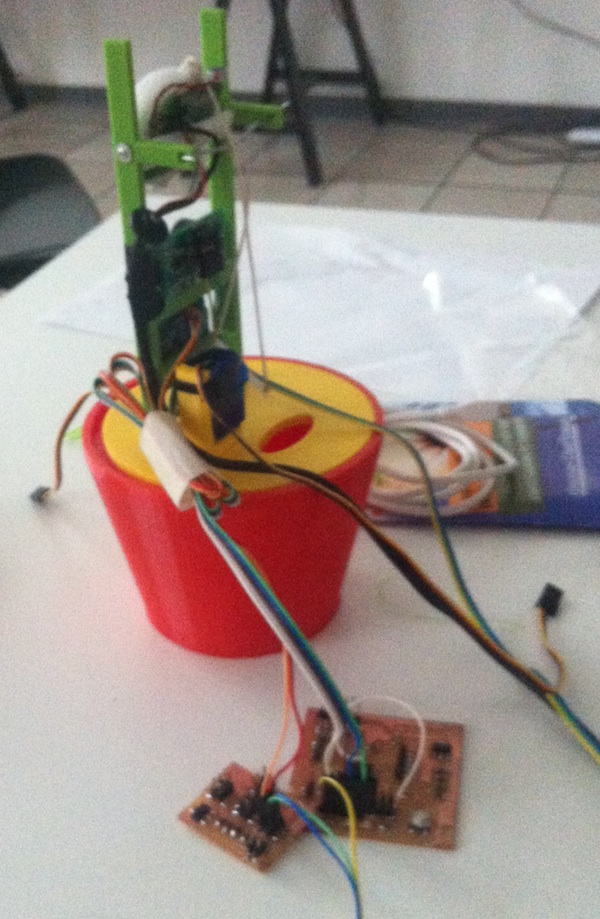
I printed the second version of the eyeball, and started integrating it with the USB camera. The size was right, the small notches on the PCB fit the pegs I added to the design and the press-fit bar holding it works great. I used my lighter to melt and press a bit the plastic joints for a better fit.
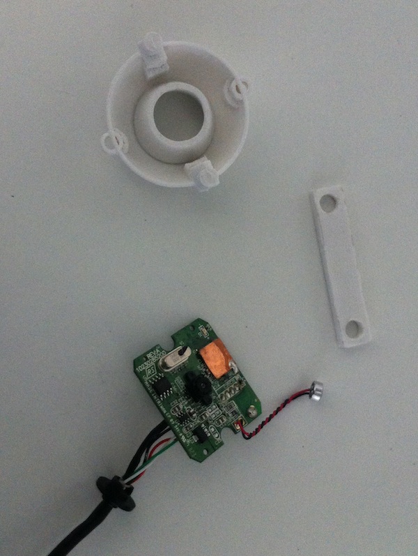
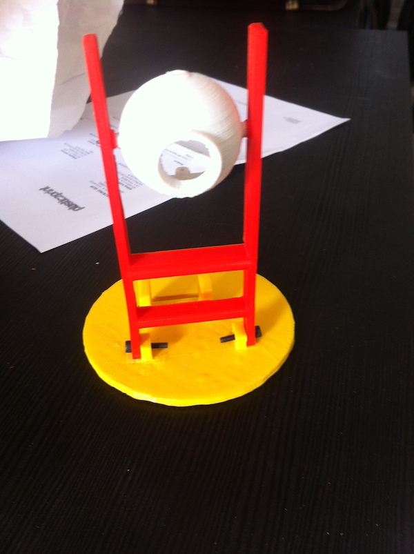
I could also finally make a first version of the tilt mechanism, using some solid wire which will replaced later by a fishing line, and add the screen to the assembly.
Please notice the pile of Cactuses in the background. The lab will be full of them everywhere by the time I'm finished with the first prototype.
28 May 2014
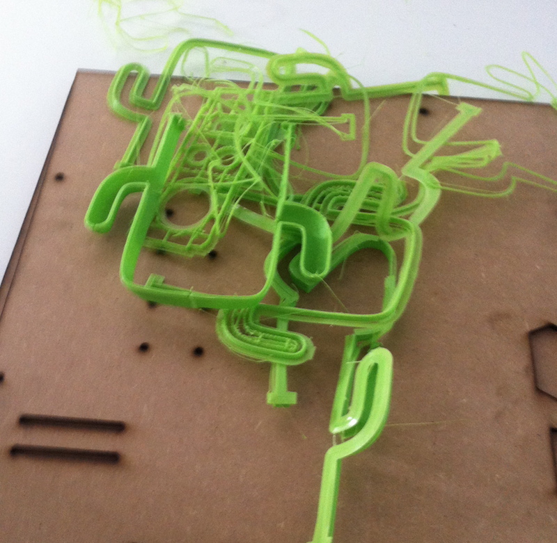
Today I started to test assembly of the printed parts. Even if not the final design these test allow me to figure out dimensions and work on the pan-tilt mechanism, and see if the actual electronics fit into the case.
Also I think my 3D printer is starting to feel some stress of all night long prints, and it's trying to tell me so in some obscure language:
27 May 2014
Less than a week to go!
Thanks to the cemetery tests I managed to print two pair of cactus cases, where the front part of the cactus came out pretty well, while one of the backs printed without support materials was pretty messy. For reference I show here the bad version, you'll see the right one in the final project.
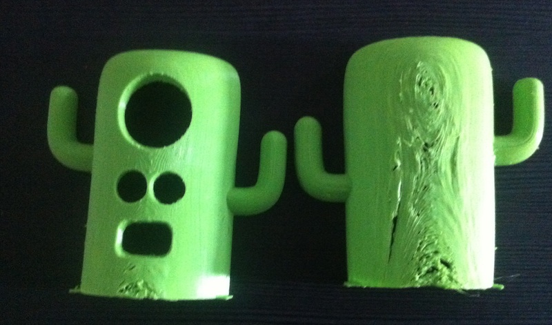
Printing both halves with support material, laying on the printer bed was finally the best setup I found. I plan to join the two halves with tiny screws on the bottom plate and using some middle support between them.
Only problem, removing support material was not pleasant at all, and scissors and knife were foundamental for doing it:
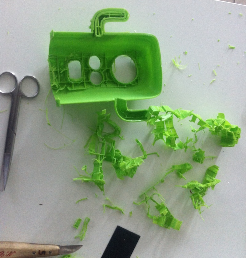
Lesson learnt: use support material only if strictly required.
Second lesson: get a dual extruder printer and water soluble support material.
Third lesson: do it in composite next time!
26 May 2014
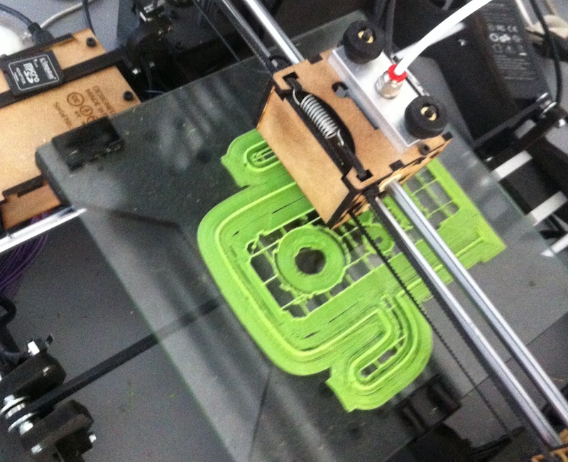
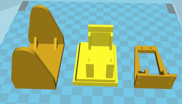
Time is running very short, and most of the project has still to be developed. I spent the last two days working on making a first 3D printed version of the project case. This is probably the most difficult part to be printed, both for its size and because its hollow inside so it needs support material.
I approached this task using nights for sending prints and working on fixing both the print settings and the models during the days. The case model couldn't be printed vertically, as it was taller than printer height, plus a solid case would make very difficult to add internal electronics to it, especially on the cactus "arms" if I ever manage to get there!
Printing the case resulted in what we nicknamed the cactus cemetery, holding prints not sticking well for some reason, aborted for other reasons or simply made for testing print settings.
I hate to say it but the cemetery did grow much much bigger at some point, but I'm too ashamed to show the picture!
24 May 2014
The 3D modeling work took me almost a full week. The positive side is I now handle pretty well Rhino, which I must say even in beta (the Mac version is in beta and free for now), proven to be very solid and powerful.
I started modeling the eyeball, redid it a couple of times, then moved to the pan and tilt mechanism, the holder for the sensors, OLED screen and finally the case. Before that I had to model all the electronics too, so I could be sure about their fitting inside the quite crowded case.
The case itself was quite difficult. When I first modeled it in the concept phase I must admin I had no clue about what was going inside. I didn't think about space for the ultrasonic sensors, which require to be entirely uncovered to work properly.
I learnt this in few iterations, where I truly played guesswork trying to make a case mesh that would let them show up only the necessary amount. As you'll see in the final design they finally are positioned to extend completely out of the case.
Result is that my project now has nostrils too.
15 May 2014
Google is evil! I had found a great solution for speech recognition using their speech API, yet they switched it off before I could show my project to the world. Even if this was totally unfair from their part. I share here the miracle snippet that was giving to the world access to a great service:
arecord -D plughw:1,0 -f cd -t wav -d 3 -r 16000 | \
flac - -f --best --sample-rate 16000 -o out.flac; \
wget -O - -o /dev/null --post-file out.flac --header="Content-Type: audio/x-flac; rate=16000" \
http://www.google.com/speech-api/v1/recognize?lang=en | sed -e 's/[{}]/''/g'| \
awk -v k="text" '{n=split($0,a,","); for (i=1; i<=n; i++) print a[i]; exit }' | \
awk -F: 'NR==3 { print $3; exit }'
This snippet records a 3 seconds audio file via ALSA from the microphone embedded in the USB Webcam, encodes it in FLAC format, posts it to the Google speech API then parses the results in a text string. Isn't this great? This is the reason I consider *nix one of the best inventions of humanity. Cannot say the same for Google by the way.
12 May 2014
If you are reading this log you might wonder why I spent so much time on the camera! The problem is that it is one of the most prominent part of my design and that most of the modeling work I need to do depends on it.
Since I changed my idea I had to redesign the eyeball, but now that this is fixed I can concentrate on the looks of my final project and started modeling it in Rhino.
I built first an example of the tilt mechanism and started to get in trouble with the 3D printing work:
11 May 2014
Time is running very fast and I'm still struggling with the camera. I think I will follow Neil's advice and move on with a spiral development dropping the Raspberry camera for something that already works and is proven to be easy to integrate.
I decided will use a UVC-compatible camera for PACO. The video acquisition will be done using mjpeg-streamer which allows to capture video in realtime from the camera and also provides the nice feature of exporting it in several format, as animated gifs, as VLC streams and so on.
The software itself is quite CPU intensive, giving around 30% load at 5 fps on the Raspberry, but this is really due to Raspberry PI limited power, as all the picture encoding must be done in software. Scaling up to a more powerful board the same solution will give full framerate and I think this is the wisest choice for now.
Having the UVC camera also gives the possibility to use the microphone for speech recognition without needing a separate board attached to the Raspberry, and finally also allows to take pictures using the uvccapture tool.
Sometimes it's difficult to pick the most evident choice: the 25 Euros Raspberry camera looked shiny and powerful, but a 9 Euros USB webcam still remains much more practical and suited for the project.
29 April 2014
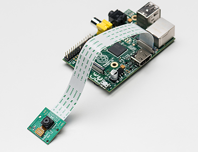
I finally worked a bit on the Raspberry camera. It has good specs, an Omnivision 5647 processor with great specs, capable of 5Mp stills and 1080p at 30fps video.
Unforturnately, the good news ends here. First problem is the cable, it needs a flat ribbon cable to be connected to the Raspberry and up to now I couldn't find any longer than the provided one with the camera (~20cm). This makes it really difficult to use it in my project, as the whole Raspberry would have to fit inside the cactus main body, that would mean a huge cactus!
Other issue is the power consumption. The camera uses up to 250mA, which implies the Raspberry cannot be powered by a common USB charger, but needs one with at least 1A or more to work properly.
Finally, while there's an official v4l2 driver for the camera, it's quite a pain to make it work. Just loading the module would result in the following message from v4l2-ctl:
v4l2-ctl: error while loading shared libraries: libv4l2.so.0: cannot open shared object file: No such file or directoryI had to resort to an obscure trick to load the appropriate module on the Raspbian distribution, invoke the raspistill before loading the module:
raspistill -o picture.jpg sudo modprobe bcm2835-v4l2 v4l2-ctl --overlay=1
All of these make me think maybe the camera is not the right solution for PACO. It would tie the project to the Raspberry, which while very cheap is quite limited in processing power and makes development quite a pain.
25 April 2014
I spent most of the past weeks working on my side-project, the opening of FabLab Cascina! I'm still keeping up with classes but didn't work much on the final project.
The relevant news is I had the opportunity to get a Raspberry Camera and plan to start doing tests with it for the PACO's vision system.
Moving to the new lab has also the advantage that I will have access all the time to many tools so hopefully this will speed up development.
Another good progress is on the controller board, for the output devices week I made my own Arduino clone and plan to use it for controlling at least the motors and ultrasonic sensors.
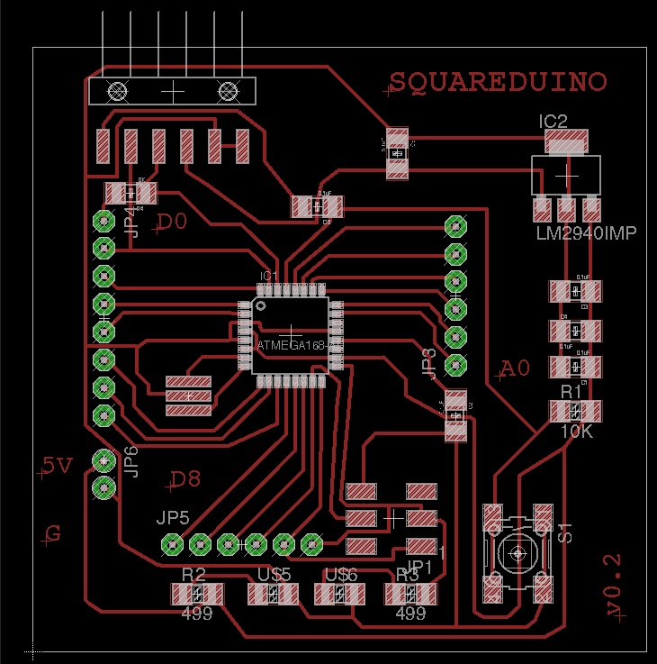
I called it Squareduino and hopefully this form factor will be a good fit into the PACO case.
Finally during the Input devices week I made a capacitive touch board, I'm not sure I like the idea of fixed touch areas in the cactus body, but it could come handy for the project.
21 March 2014
Progress on the project has slowed down, as I encountered a significant bottleneck on the serial camera throughput.
I tested the camera on an Arduino Leonardo using the code provided by Sparkfun.
The result was quite poor in terms of frames per second, as I could take a picture in just 6 seconds! This result is not really useful for my project goals, as I was planning to offer the possibility to use the companion video for computer vision, web conferencing and other mundane tasks.
The final conclusion is that while keeping the original architecture for my project, I will turn to more powerful hardware as the main controller board. I'm currently looking for alternatives such as the Raspberry PI or Arduino YUN to achieve this goal.
Also, I think that switching to such kind of board will significantly reduce the cost of the overall solution, as a very cheap USB camera would be now usable. I'll write more as I weight the different possibilities.
4 March 2014
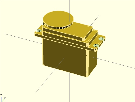
I completed the Servo control board and programmed it with the two Channel software PWM. I could finally move one and try it with actual servo motors to see if it worked.
In order to have a working rig for actually moving the camera, I started from an existing set of models downloaded by Thingiverse which I planned to print using the Ultimaker 2.
Additionally, to test if the models were suitable for my HS-311 servo, I designed a model in OpenSCAD to match my motor specs. The model source is also available on github.
The actual 3D printing of these models was not straightforward. Due to some lower quality PLA material, the initial versions of the printed object where not suitable for use. The filament was not sticking well and also skipping significantly while extruded. The print itself required several hours so I was very disappointed by the result:
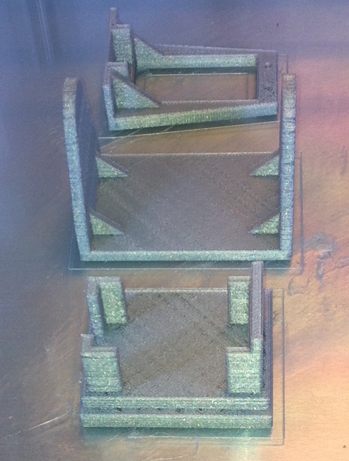
In order to achieve a better result, I tried printing again one of the parts with a different filament and raising the temperature to 230 degrees. This time the printed part looked far more solid, but unfortunately the printer stopped extruding at some point, resulting in the following:
Finally I was able to produce the parts, achieving a better quality by slowing much the printing process to around 50% speed, and by rising temperature to 235 degrees. Most of the parts came out good enough for use, except one of the two bits holding the camera. In order not to monopolize the lab's printer I decided to put some tape to make parts stronger without printing them again.
The assembled pan-tilt movement still needs few tweaks for being ready to be used for my project, but the initial result looks promising:
25 Feb 2014
I'm still working on completing the Servo control board, for which I had some trouble in finding the right components and soldering the connector pins.
I did anyway experiment with several designs for the pan-tilt movement, which I plan to build using the 3D printer during the upcoming week.
For the camera module I dediced to use a Linksprite Serial Jpeg Camera. This module will allow to grab picture frames directly encoded in JPEG format at several resolutions. I will be able to transfer such frames to a temporary storage and then get them accessible to the main PC control unit of the digital companion.
I investigated other possibilities, such as using directly a Toshiba Camera module such as the TCM8240MD, but as far as I understood this module can't be controlled by any 8bit AVR controller, and even encoding JPEG frames would require an ARM processor or a dedicated DSP unity.
18 Feb 2014
I've identified most of the components I will be using for the first version of the project. During the upcoming week I will start creating the movement mechanism for the digital companion eye, using two servo motors and an ATTiny44 processor. As agreed with my instructor milling and stuffing the control board will be part of my next week assignment, and I plan to have this component of the project completed by next week.
10 Feb 2014
Started researching components needed for the electronic part of the project. I decided to start assembling a first version of the project using ready-made electronic components, and do a basic software interface to control them via serial link. I will be then replacing each module with a self-fabricated one.
30 Jan 2014
Defined the basic project concept and made initial 3d models for the case.
Setup the project milestones and Trello in order to track progress.
11 Feb 2014
Created logo and defined name for the project: "PACO". Created a more detailed 3D model for the project case.
