
Networking
This week goal is to establish a network between two or more different microcontrollers. For the assignment I decided to test the NRF24L01+ ISM modules for connecting my Arduino clone board built during the last week with a Raspberry PI. I also used a serial link for getting input from the Tiny Midi board built during the Input devices week to the Arduino clone.
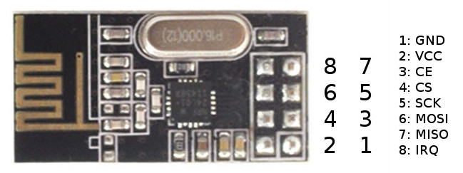
The NRF24L01+ module
This module provides a very low power radio solution capable of up to 2Mpbs data rates in the 2.4Ghz band and very low power consumption. Using an SPI interface plus two dedicate pins, it allows to link up to 6 nodes at a time in one among 127 channels. It also offers automatic error correction, dynamic payload size and a wealth of of other features.
The IC itself comes in a very small package. Most of the people using this rely directly on pre-built module breakout boards, that can be currently found as cheap as 3 Euros for a single piece. When buying ths module you should consider to get the "plus" version of it, as it allows to operate to lower baudrates 250Kbps and lower error rates. The previous version is instead locked to 2Mpbs, and this is the rate that should be used to make newer and older modules interoperable.
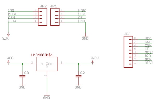
The NRF24L01+ has a range of 1.8v - 3.7v for power, while the logic is 5v tolerant. My Arduino clone board doesn't provide any 3.3v power outputs, so one of the first things I had to do is to design a power regulator circuit around it.
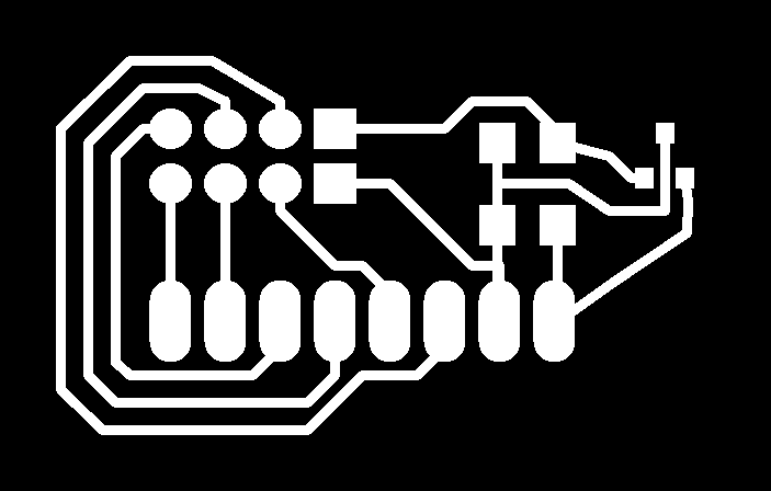
The goal was to make both a regulator circuit and to break out the NRF24L01+ pins allowing to use a breadboard for connections or male pin headers.
I came up with following schematic and board layout:
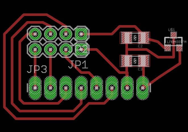
I directly soldered the modules to the board as I didn't have the right connectors. Eventually I will also create some stickers to name out the different pins.
How does it work?
The operation of the NRF24L01+ module is based on the concept of named pipes. When communicating the nodes using the module define a shared set of pipe addresses, then use two or more for exchanging data.
In a two-nodes configuration this works like the following:
Node1                                  Node2

Writing Pipe [0xF0F0F0F0E1LL] -------> Reading Pipe [0xF0F0F0F0E1LL]
Reading Pipe [0xF0F0F0F0E1DD] -------> Writing Pipe [0xF0F0F0F0E1DD]
In a multiple node configuration things work a bit differently. There is a main node listening to all writing pipes for the other nodes, and answering on each node reading pipe, while the remaining just deal with their own reading/writing pipes. In this case the main node doesn't own any pipes, but uses the ones defined for the remaining nodes.
The datasheet describes this in more detail.
Using NRF24L01+ on the ATTiny
The main reason because I didn't test this is that I was afraid that the radio library plus some input gathering code wouldn't fit the ATTiny44 memory footprint. I plan to get some ATTiny84 or 85 to test the module with them.
Even if I didn't use it with the ATTiny several people reported this could work using the ATTiny84/85 USI interface. Furthermore some solutions to make this work using just three pins are available, using a circuit like the following:
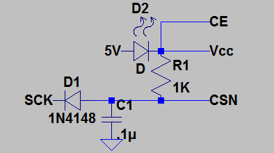
The trick is to connect the CE pin directly to high (so the IC is always enabled) and to use the SCK clock to enable the CSN pin, which must be pulled high then low before every transmission. When the SCK pin goes high for several ms, the capacitor charges and the CSN is pulled high, then discharge with the diode when SCK goes low. During the transmission SCK will go high for shorter periods and won't be able to charge the capacitor, keeping CSN low.
Anothe smart solution proposed is to use a red LED instead of a regulator, as it will use between 1.8-2.4V out of the 5V available, leaving enough power for the radio. All of this is described in this post.
For the software part, there's a specific library for ATTiny85 that can be used in this github repository.
Using NRF24L01+ on the ATMega328p
Having hardware SPI makes using the module much easier. The required connections are the following:
NRF -> ATMega328p

MISO -> 12 (PORTB4, pin 16)
MOSI -> 11 (PORTB3, pin 15)
SCK -> 13 (PORTB5, pin 17)
CE -> 9 (PORTB1, pin 13)
CSN -> 10 (PORTB2, pin 14)
The CE and CSN pins are configurable. There are two main libraries that can be used for controlling it: the MIRF library and the RF24 library.
There are several differences between the two, the MIRF library is much simpler and less configurable, while the RF24 provides methods for configuring most of the features described in the datasheet. While the former is available for the ATTiny too, the latter has been ported to other platforms such as the Teensy and the Raspberry PI.
For this reason I decided to use the RF24 library for my test project.
Using NRF24L01+ on the Raspberry PI
As I wanted to communicate with the Raspberry PI, which I'm also going to use as part of my final project, I researched support for the Raspberry.
On the hardware side the connection is done using the Raspberry GPIO ports, with the following connections:
NRF -> RPI

MISO -> GPIO9 (pin 21)
MOSI -> GPIO10 (pin 19)
SCK -> GPIO11 (pin 23)
CE -> GPIO8 (pin 24)
CSN -> GPIO25 (pin 22)
On the software side the port of the RF24 library for the Raspberry allows to use almost the same code used for the ATMega. Full instructions can be found here.
The only pin that must be configured using the library is the CSN, specified in the constructor of the radio object:
// spi device, spi speed, ce gpio pin
RF24 radio("/dev/spidev0.0",8000000,25);
Serial communication
In order to read data from the TinyMidi board and send it to the radio connected on the ATMega328P board, I used a simple serial communication. Since the ATMega board already was using the hardware serial port, I used the SoftwareSerial library to connect to ATTiny serial communication pins.
This library allows to use any pair of free pins on the ATMega like they were an hardware serial port. The only limitation is that the pin used for RX should support change interrupt. In my case I used PORTB0 (D8) for the RX channel.
Putting it all together
In my test project the ATTiny sends newline terminated strings corresponding to key down - key up events on the keyboard, corresponding to a pad number followed by the equal sign and a 0 or 1 if the pad was pressed or released.
This data is read from the Software serial on the ATMega and sent on the air using the NRF240L1+ module as a pair two uint_8 integers to the Raspberry PI, which then converts them using a mapping to keystrokes, suitable for example for controlling a media player or a videogame.
Sending keystrokes to the RaspberryPI is done using the pikeyd project, which maps the configured Raspberry GPIO pins to actual keypresses.
