
Output Devices
This week assignment is about adding an output device to a board we have designed. For this week I decided to design and build my own Arduino-clone and also make a separate board for controlling pwm output devices. I then used the two for controlling a micro-servo powered robotic arm and play with SMA.
Building my Arduino clone
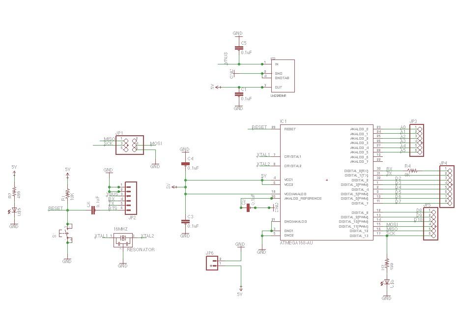
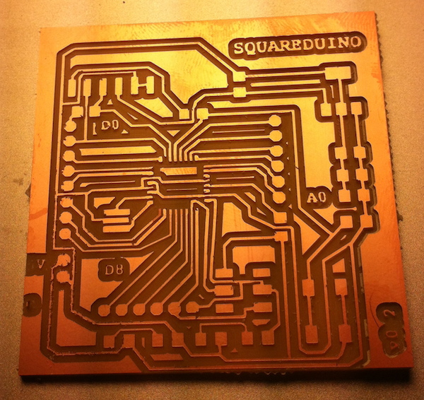
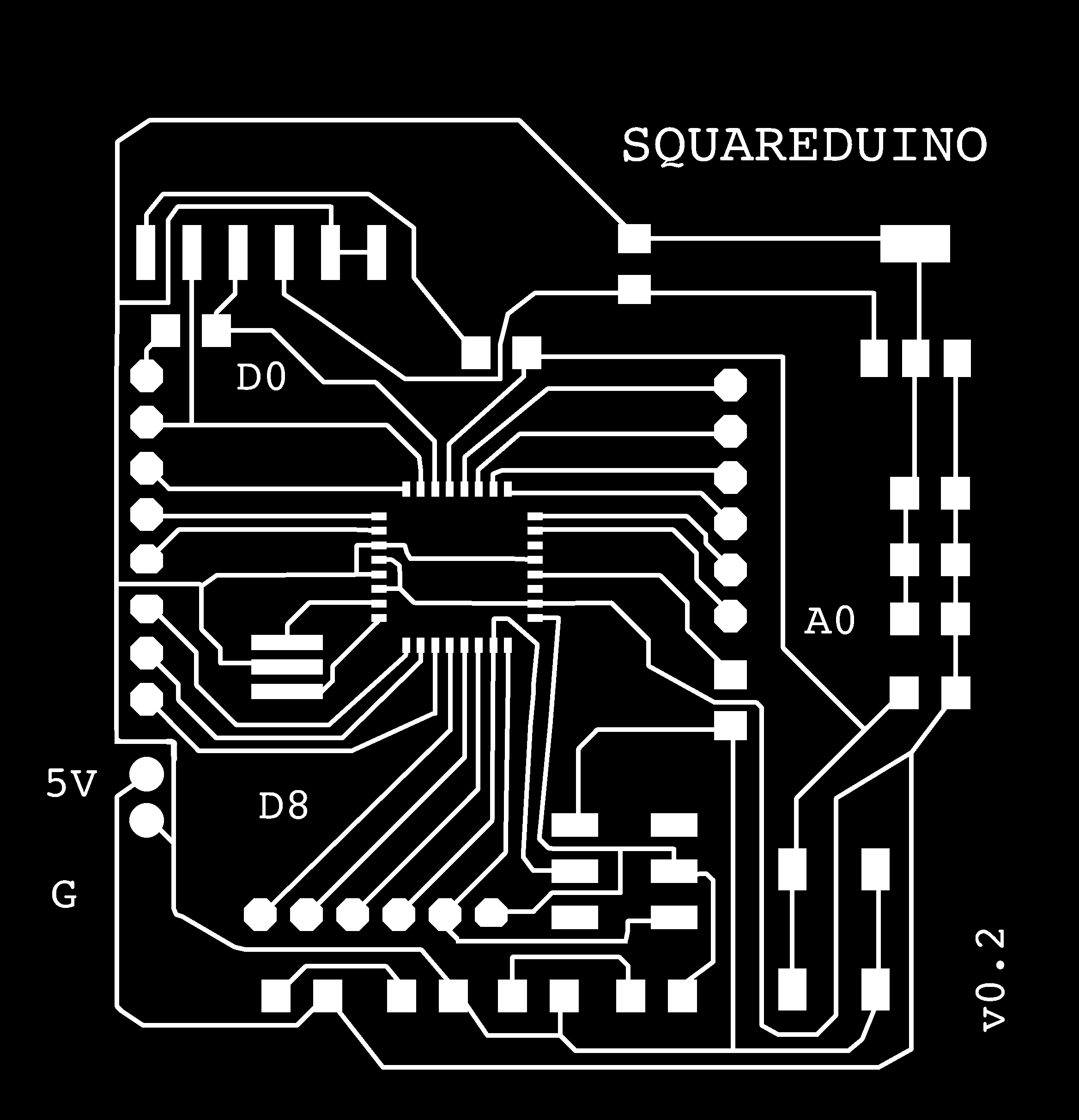
My goal was to create a small form factor Arduino using the ATMega328P and exposing as many pins as possible, and also being able to use it directly in the Arduino IDE. At first I wanted to replicate the Arduino pins layout, but realized it would either make the board too big for reusing it as the heart of my final project and also would give me a hard time having to create a single layer layout for components.
My design is loosely based on the Arduino Pro schematics, with some differences due to the lack of a switch for picking the battery supply.
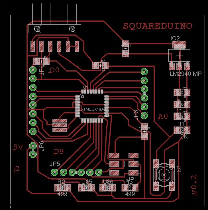
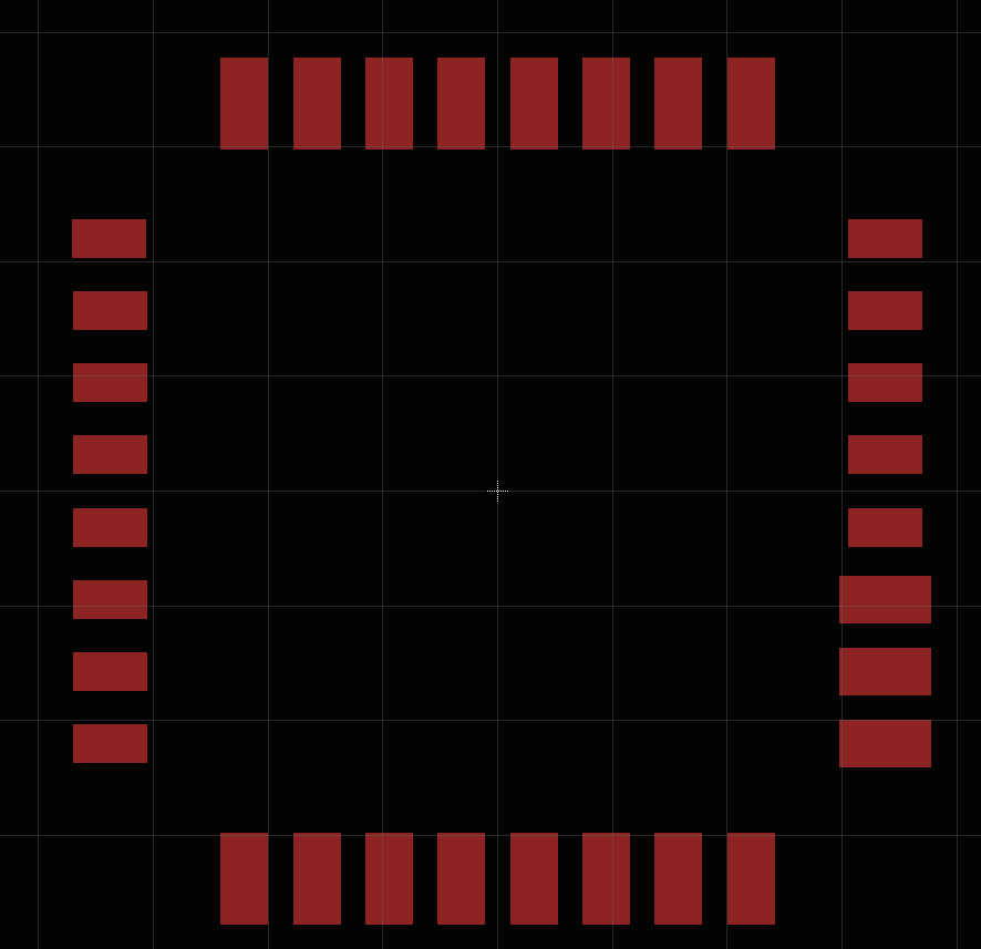
As I quickly realized trying to make it, the first version of the design had a significant flaw: the ATMega328P has a TQFP32 form factor, meaning the MCU pads are really close one to another, and they couldn't be milled in the size specified by the Eagle library using the available 1/64'' inch bit.
Following my instructor advice, I had two choices: find another better designed library or make my own part for this form factor. Honestly I couldn't find another library containing pads with a different spacing, so I went for the make my own part route.
Actually the process wasn't really difficult. I just had to resize each pad in the TQFP32 "package" to be much smaller. This can be done selecting the size of the pin from a dropdown box, so the process was quick.
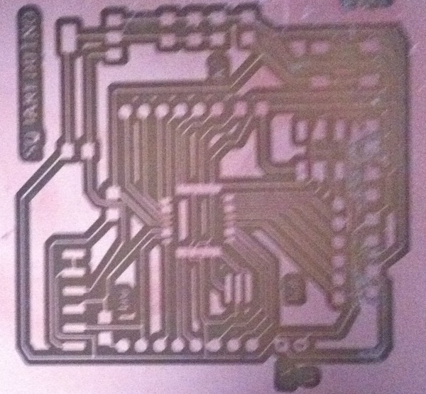
Finally my board was ready to be milled with the 1/64'' bit, and the process took almost 45 minutes at 4mm/s speed. Stuffing the board was also less painful then I expected. I first tried to solder the ATMega328 by putting solder all over all pins then removing it with the soldering braid. This didn't work really well, as it was fairly difficult to remove all the solder joining the pads and still having them make contact with the pins. At the end I resoldered each pin individually.
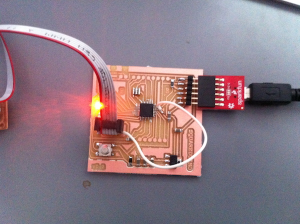
As I planned to normally program my board using a bootloader, via the FTDI cable, and also to make the design process a bit easier, I intentionally omitted to join the RESET pin in the ICSP header to the RESET bus. For uploading the bootloader I just soldered a wire from the RESET pin to the RESET bus.
While stuffing the board I also realized I didn't have a 16Mhz resonator, and considering I had a 5V IC Reg on the board I realized I could use the 20Mhz one which is anyway supported by the ATMega, not knowing this would bring some consequences discussed later.
Programming the board
In order to be able to use a 20Mhz resonator, I quickly discovered I needed to compile my own bootloader and customize the Arduino IDE, which only supports 8Mhz and 16Mhz boards, and get prepared for some trouble, i.e. Sparkfun stopped selling 20Mhz boards for this reason.
I knew that tweaking with the Arduino IDE could be a bit tricky, so I decided to use the 1.0.5 version, the latest one supporting only AVR architecture. In fact newer versions (1.5.x) support multiple architectures and made the customization process much harder.
Luckily the Optiboot bootloader, the one Arduino Uno uses, can be compiled for 20Mhz support.
Building a custom Optiboot can be done by going into the bootloaders/optiboot folder inside the Arduino distribution, and adding the following to the Makefile:
#
atmega328_20MHz: TARGET = atmega328__20MHz
atmega328_20MHz: MCU_TARGET = atmega328p
atmega328_20MHz: CFLAGS += '-DLED_START_FLASHES=3' '-DBAUD_RATE=115200'
atmega328_20MHz: AVR_FREQ = 20000000L
atmega328_20MHz: LDSECTIONS = -Wl,--section-start=.text=0x7e00 -Wl,--section-start=.version=0x7ffe
atmega328_20MHz: $(PROGRAM)_atmega328__20MHz.hex
atmega328_20MHz: $(PROGRAM)_atmega328__20MHz.lst
atmega328_20MHz_isp: atmega328_20MHz
atmega328_20MHz_isp: TARGET = atmega328__20MHz
atmega328_20MHz_isp: MCU_TARGET = atmega328p
atmega328_20MHz_isp: HFUSE = DC
atmega328_20MHz_isp: LFUSE = FF
# 2.7V brownout
atmega328_20MHz_isp: EFUSE = 05
atmega328_20MHz_isp: isp
Then compiling the bootloader using the provided omake script, like the following:
omake atmega328_20MHzI could then have used avrdude to upload it, but as already mentioned I wanted this to be compatible with the Arduino IDE. So it was necessary to edit the boards.txt, located in the hardware/arduino folder adding an entry for the new board.
atmega328_20.name=Arduino w/ ATmega328 @ 20Mhz

atmega328_20.upload.protocol=arduino
atmega328_20.upload.maximum_size=32256
atmega328_20.upload.speed=115200

atmega328_20.bootloader.low_fuses=0xFF
atmega328_20.bootloader.high_fuses=0xDC
atmega328_20.bootloader.extended_fuses=0x05
atmega328_20.bootloader.path=optiboot
atmega328_20.bootloader.file=optiboot_atmega328__20MHz.hex
atmega328_20.bootloader.unlock_bits=0x3F
atmega328_20.bootloader.lock_bits=0x0F

atmega328_20.build.mcu=atmega328p
atmega328_20.build.f_cpu=20000000L
atmega328_20.build.core=arduino
atmega328_20.build.variant=standard
With all this done I could easily program the bootloader on the board using the Arduino IDE.
Uploading a sketch, unfortunately, did not work. At first I tried to change several times the serial upload speed, with no success. As far as I understood this is due to the fact that a different clock speed alters the serial baudrate in the bootloader. I could have fixed this using an "alternative" baudrate like 500000, but my operating system, OSX has fixed baudrates to choose from and couldn't make it work.
Finally I managed to upload sketches using the ISP, by holding the "shift" key while pressing the upload button in the Arduino IDE. This is far from optimal, but works pretty well at least till I will get a 16Mhz resonator.
Adding Output Devices
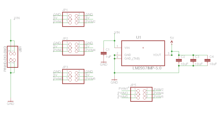
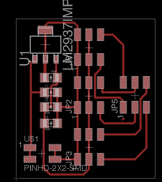
The ATMega328p PWM output wouldn't be able to power many servo motors or other power-hungry devices. So I decided to make a small daughter board with a built-in 5V regulator, the right pinout for servo motors, and power pins for hooking up an external 12v 1.5A wall power supply.
The board has six pins for pwm, six three-pins connections for motors and connector for power supply and ground coming from the main board.
My design was very simple, yet I quickly found some problems. The first version of the board lacked a capacitor at the regulator input, and had a single 10uF capacitor for the output, and was not working as expected. The reason I discovered this was that measuring the regulator output with the multimeter resulted in more than 10v when powered with the 12v supply.
Getting back to the datasheet, I redesigned the board adding a 1uF capacitor on the regulator input and three 10uF capacitors in parallel for the output. Actually the datasheet suggested a .47uF capacitor on input and at least a 22uF on the output, so I tried to put larger components to be on the safe side.
Desktop Robotic Arm
Finally I was able to test my designs with some real outputs. I always dreamed to have a small robotic arm sitting on my desk, and never thought I could build one in such a small time with the help of self-made electronics and a 3D printer.
I didn't design the robotic arm from scratch, but started from an OpenSCAD design found on Thingiverse. I printed all the parts using the lab 3D printed, and added one larger HS servo for the base and three HS-55 micro servo motors I had available. These are quite cheap (6 eur in bulk package) and very tiny. Actually they are also very delicate and easy to break if not handled with care, probably because of the tiny gears inside them.
The design includes a small rack-and-pinion mechanism for picking objects, but I didn't have enough motors.
The software sketch I designed for controlling them was very easy to write. This is because I used the Arduino Servo library, which wraps all the PWM duty cycle routines into a super-easy package.
The sketch basically sets a start position for the servos, and reads commands on the serial port which control each motor in 5 degrees increments, smoothing the movement in 100ms 1-degree moves. The following string:
A0,B1,C1,D1for example, will move the base servo on the left 5 degrees, and the others down 5 degrees. I also added a pause command (P0), that allows to move the same servo in opposite directions in a single line, and a reset (R0) command that puts all the servos back into position.
You can of course control the board with a serial terminal, but I also wrote a small Python script allowing to have "choreographies" in separate text files and reproduce them in a loop, adding automatically some delay for each line.
This is the result of such a coreography:
Playing with SMA
During the lesson and reading the student list I was intrigued by how easy using SMA materials looked. I was planning to work on those from long time and had the chance to get some Flexinol wire to test.
The wire I used is 0.1mm (.004'') thick. As the tutorials suggested I followed the rules to calculate how much wire I could use for 5V output.
Looking at the datasheet, the recommended current for this wire is 180mA, with a resistance of 150 Ohms per meter.
This gives the following:
5V / 0.18 Amps = 27.7 Ohm

27.7 Ohm / 1.5 (Ohm/cm) = 18cm
So I cut 18cm of wire, crimped the sides with some jewelry crimps I usually keep for soldering pin-header connector to wires, and soldered both ends to some bits of FR-1 boards.
I was planning to make some more creative application for the SMA, but started with a plain sheet of paper:
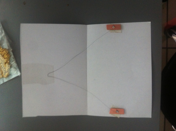
I first tried using 100% duty cycle directly on a PWM pin, with little if no movement. I then moved using the power provided by my daugher board instead. I didn't design any additional board for it, but directly powered the wire touching the pin with the crocodile connector.
The first test showed a significant movement, only problem is that when the wire is not powered, and cooling down it needs some weight to get back to the original position, showing a bit different behaviour than the one in the videos. The pull force of 150g stated in the datasheet is obviously related to the full wire, so I still need to figure out an optimal setup for it.
Conclusion
I spent a significant amount of time on the Arduino board, and little time was left for making several output devices as I wanted. I will need to make several others for my final project, so I will investigate deeper for example the audio amplifier design and led matrices over the next few weeks.
Files
Robotic Arm: Arduino Sketch, Python Script, Coreography
