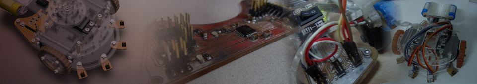
Introduction
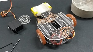
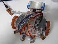
The idea of these robot is to create a modular diferential robot, the motion will made by a hacked servomotor (click here for my tutorial) because de driver control of the speed and the direccion of turn is inside the servo.
For more information about this project see: Aplication, Implications & Dissemination PlanPART 1: Mechanical
Mechanical Design
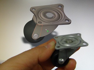
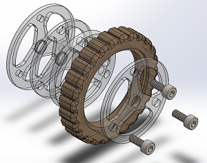
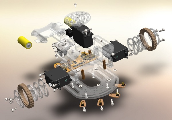
All the parts are modeled 3D in CAD, included the electronic boards, bolts, servomotors, caster wheel, batteries, etc. The image and the video show the exploded view of the assembly. The CAD files can be download here.
Mechanical Materials
Fabrication
Basically I used three CNC machines, the laser cutter (Epilog-Legend 36EXT), the mini milling (Roland Modela MDX-20), 3D-printer (MakerBot-Replicator).
Structure
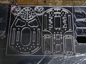
All the structure, are made with 6mm acrylic cutted with laser. Download cutting files here.
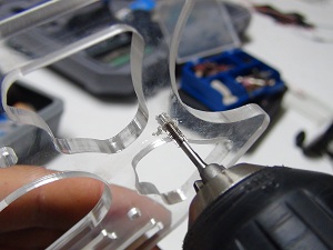
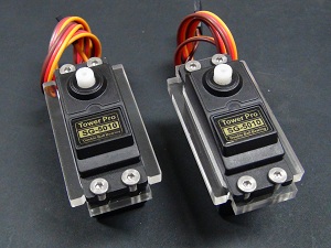
To fix for example the servomotors, I threat the acrylic structure with a M3 tap (helped with the electric screw driver).
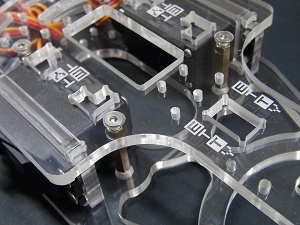
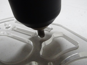
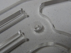
Also I needed to countersink the holes of the bolts that fix the Bronze columns (connecting the top plate with the bottom plate of the structure).
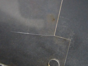 Bad Corner
|
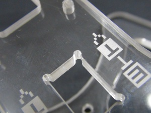 Good Corners
|
Wheels
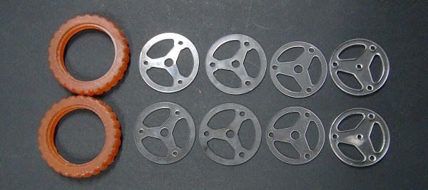
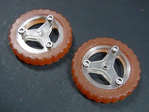
The wheels has two parts, the rim (cutting files) and the tire (mold file). The urethane rubber have excellent grip, so tire was made with molding and casting process using this kind of rubber.
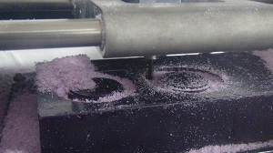 |
Milling the machinable wax to make the mold for the tires. For this job has used: |
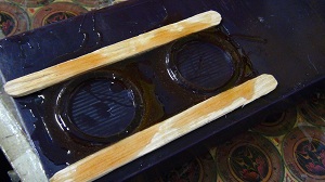
Acrylic ring placed to create the flange seat geometry on the tire side. | |
Urethane resin casted direct in the machinable wax mold. |
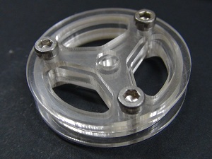
The rim was cut with laser and then assembled with three M3 bolts (each tire).Why so many layers (actually 4 layers), because the externals are the flanges of the rim, the internals are the beat seat, the nearest (two layers) to the servo has the splined hole to fix the servo axis.
Part 2: Electronics
Electronic Design
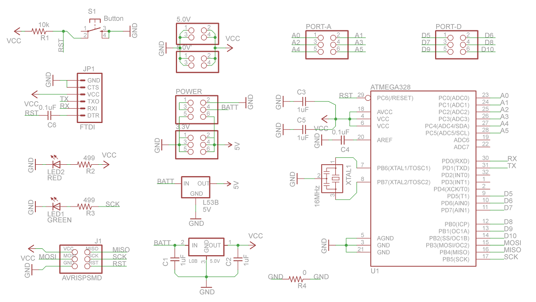
The board is an Arduino UNO modified to fit the robot structure (Eagle files). So I used a ATmega328P and a 16MHz resonator. This allow to burn the bootloader like a normal Arduino UNO. Also included an independent power supply (5V-1A) for the servo motors and other for the microcontroller.
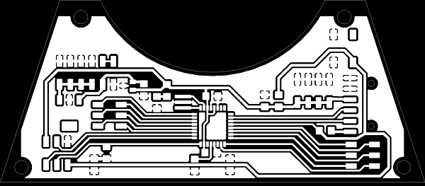 Board for milling |
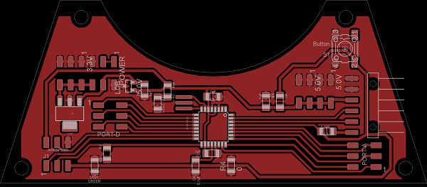
Component places |
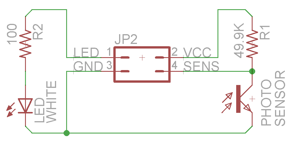
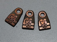
Aditionally are four(4) sensor boards (Eagle files) that function like shields for the principal board. The conector is THD because the board has the sensor in the opposite side of the connector. |
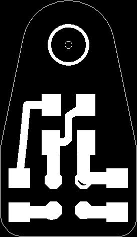 Board file for milling |
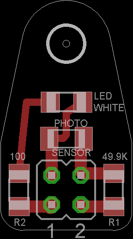
Components |
Electronic Materials
|
|
|
Circuits Manufacture
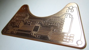 |
The milled board was sanded with steel braided sponge to polish the copper surface. |
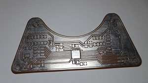 |
Then was tinned to protect the copper layer from the oxidation and prepare for the soldering process. |
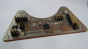 |
Finally all the components was soldered to the board. |
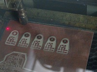
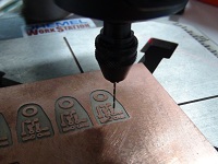
The small boards for sensors, was milled, then cutted with laser, and finally drilled to made the holes for the THD Pin-header.
Battery Holder
The Li-Ion battery that I used has 16340 form factor, the dimension didn't fit any common battery holder in the local market, or the Fab Inventory. The solution was create my own battery holder (3D printing file).
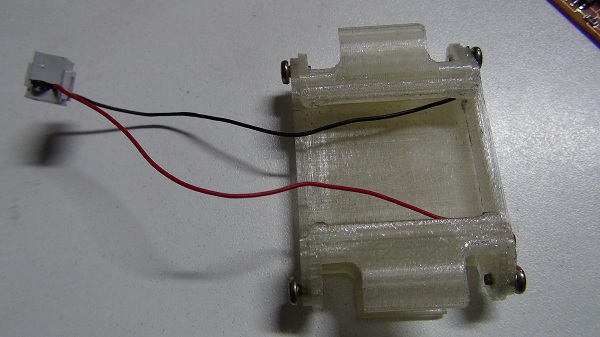 All the structure was 3D printed. The screws are for make electric contact. The cables are internal routing to made a battery pack with 7.4V (3.7V+3.7V). Also the fixation is with mechanical block using the screws of the caster wheel.
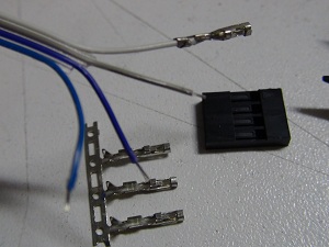
Connectors & Cables
To connect the sensors boards (shields) to the control board (Arduino UNO) I prepared cables and connectors using flat wires, female pinhead connector.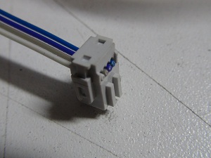
Part 3: Programing & Testing
Burning the Boot Loader
Before this step, disconect the battery power supply, all the sensors and servomotors.To burn the boot loader connect the programmer to the AVRISP port, also connect 5V supply voltaje (in my case the FTDI cable).
Setting the arduino:
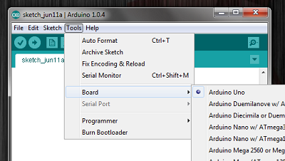 |
Choose the board type. For an ATmega328P (with a XTAL or resonator of 16MHz) correspond to an Arduino UNO board. |
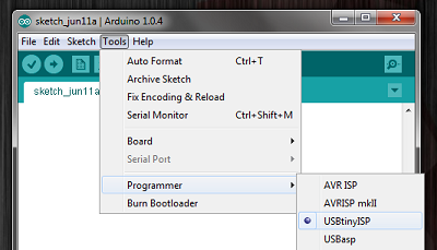 |
Then choose the programmer. (In my case FAB ISP) |
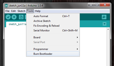 |
Finally record the bootloader and disconnect the programer. For the next steps we only need the FTDI cable. |
Programming
The line tracker program guides the robot over a black line on a white surface.
For calibration, the program first takes values of the sensors. Then start the movement secuence; going straight if all the sensors are over the black line, turning left if the right sensor detects white surface or turning right ir the left sensor detects white surface.
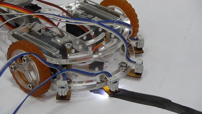
Testing one sensor lecture to get the setpoint.
The program is as show below:
#include <Servo.h>

Servo servo1;
Servo servo2;

int lights1=9;
int lights2=10;
int lights3=11;
int lights4=12;

int FT1, FT2, FT3, FT4;
int leftOffset1=0,leftOffset2=0,rightOffset1=0,rightOffset2=0;
int servport1=5,servport2=6;
int neutralspeedservo=90; // Servo motors speed zero
int startSpeed1=neutralspeedservo+20;
int startSpeed2=neutralspeedservo-20;
int rotate=50; // Aditional speed for turning
int threshhold=300; //SETPOINT

int left=startSpeed1, right=startSpeed2;

/* CALIBRATION FUNCTION FOR LIGHT SENSORS */
void calibrate(){
  for(int x=0; x<10; x++){
    // Turn On the LEDs from the sensor board
    digitalWrite(lights1,HIGH);
    digitalWrite(lights2,HIGH);
    digitalWrite(lights3,HIGH);
    digitalWrite(lights4,HIGH);
    delay(100);
    // Sensors lecture
    FT1=analogRead(0);
    FT2=analogRead(1);
    FT3=analogRead(2);
    FT4=analogRead(3);
    //Offset calibration (Acumulative)
    leftOffset1=leftOffset1+FT1;
    leftOffset2=leftOffset2+FT2;
    rightOffset1=rightOffset1+FT3;
    rightOffset2=rightOffset2+FT4;
    delay(100);
    // Turn Off the LEDs
    digitalWrite(lights1,LOW);
    digitalWrite(lights2,LOW);
    digitalWrite(lights3,LOW);
    digitalWrite(lights4,LOW);
    delay(100);
  }
  // Offset calibration (Avereage calculation)
  leftOffset1=(leftOffset1)/10;
  leftOffset2=(leftOffset2)/10;
  rightOffset1=(rightOffset1)/10;
  rightOffset2=(rightOffset2)/10;
  //Offset diferential values
  leftOffset1=abs(leftOffset2-leftOffset1);
  rightOffset2=abs(rightOffset1-rightOffset2);
}

/* PRINCIPAL PROGRAM */
void setup(){
  // Set the LEDs port to Output
  pinMode(lights1,OUTPUT);
  pinMode(lights2,OUTPUT);
  pinMode(lights3,OUTPUT);
  pinMode(lights4,OUTPUT);
  Serial.begin(9600);
  // Motors port setting
  servo1.attach(servport1);
  servo2.attach(servport2);

  calibrate();  // Start calibration secuense
  delay(3000);  // To recognice the end of the calibration secuence
  // Turn on the LEDs
  digitalWrite(lights1,HIGH);
  digitalWrite(lights2,HIGH);
  digitalWrite(lights3,HIGH);
  digitalWrite(lights4,HIGH);
  delay(100);
  // Starting the movement
  servo1.write(left);
  servo2.write(right);
}

//PRINCIPAL LOOP
void loop(){
  // Speed if robot goes straight on the line
  left=startSpeed1;
  right=startSpeed2;

  FT1=analogRead(0)+leftOffset1;
  FT4=analogRead(3)+rightOffset2;

  if(FT1<(threshhold)){
    // Speeds if the robot gone out the line from sensor FT1 side
    left = startSpeed1 + rotate;
    right = neutralspeedservo;

  }
  if (FT4<(threshhold)){
    // Speed if the robot gone out the line from sensor FT4 side
    left = neutralspeedservo;
    right = startSpeed2 - rotate;
  }
  // Show in serial monitor the speed values
  Serial.print(left);
  Serial.print(" ");
  Serial.println(right);
  // Motor movement
  servo1.write(left);
  servo2.write(right);
}
The program in action is show on the video.