Fab Lab Barcelona SuperNode /Fab Lab Sevilla /Jose Perez de Lama
Weeks 16-19++ / final project
Retablillo de las Maravillas v1.0
Developed july>>august 2013
4./ Interactivity & electronics
4.1/ Switches / characters
4.2/ Screen / interface
4.3/ Motor controller
4.4/ I/O controller & interface
[4./ electronics]
[4.1/ switches / characters]
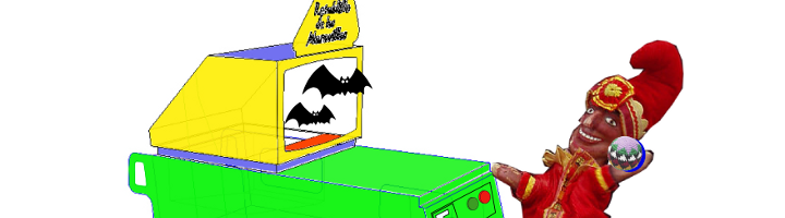
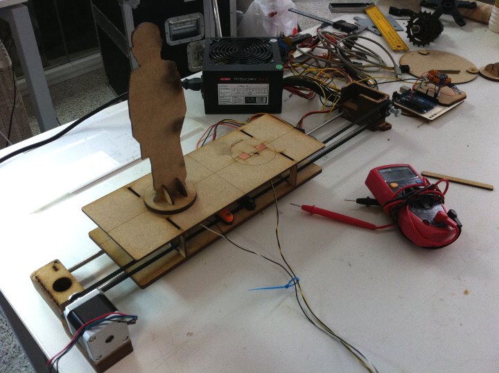
The characters on top of the moving platform function, as interfaces, actually as on-off switches. While standing in its position on the platform that keep a switch on. Once they are knocked off the switch is off. The characters are built once again with 3mm laser cut MDF, and made of a circular platform, connectors and a silhoutte. On top of the silhouette and color printed collage is glued to make the figures attractive and, if so desired, recognizable.
This is achieved setting two electrodes on the surface of the moving platform that are connected by a continuous conductive surface when the figures are on top of them. The material solution of it was using flexible self-adhesive copper film for both ends of the switch, taking care to have it as perfectly flashed on the surface as possible. On the lower side of the platform a cable is soldered to each of the electrodes connecting to the I/O board.
A secondary problem was to keep the characters reasonably in place while the platform is moving left to right and back. This is achieved using small neodimio magnets that are embedded in the precisely cut MDF pieces. It was important to finely regulate the distance between magnets not to make the figures impossible to knock off with the light balls to be used in the game. Once determined the distance, the magnets were fixed in its place with some drops of Loctite glue.
The figues still move a bit, and in a future version, two pairs of magnets could be used for each of the figures to achieve a more stable configuration.
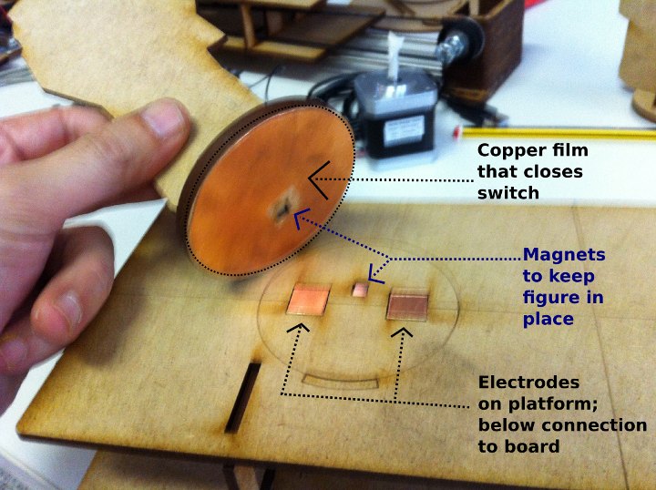


The electrodes are made enveloping MDF pieces with the right dimensions in flexible copper film, so that the contact can be made on the top of the platform and cables can be soldered in the lower part. The neodimio magnets that we had in the lab from other projects need to be adjusted to find the right strength for the figures, so that they stay in place when the platform moves but that they can be knocked down with a softball. Some testing were made with the platform in movement to make sure the electrical connection was stable. Once the position of the electrodes and the magnets were fixed i used some Loctite glue to keep them in the exact place.
[4.2/ screen interface]
As advanced before, after considering various alternatives such using an LCD screen or a Python+Tkinter interface on a computer screen, a quite low tech and efficient design was finally chosen for the interface.
It consists on a white translucent acrylic, etched and equipped with various colored LEDs, as well as two functional switches [actually an on-off switch and a push button]. Two other push buttons are placed in the interface, but ended up having no function, and just looking cool :) _ The LEDs inserted in the translucent acrylic glow in a attractive and quite visible fashion.
The system works as follows: The on-off switch connects and disconnects the system. The first time it is turned on two parallel routines [motor and timer+score] get triggered lasting for approximately 30 seconds. For the next iteration the player can press the push button that triggers the routines every time it is pressed. To turn the system off, the player presses the on-off switch.
The whole system is powered by a 12V battery, giving it an autonomy of several hours.
[4.3/ motor controller]
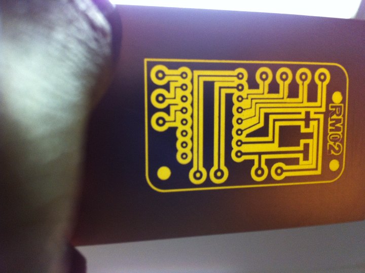
The stepper motor is controlled by an Arduino Uno and an ad hoc designed and fabricated simple board that houses a Pololu / Allegro A4988 mini board, - "A4988 Stepper Motor Driver Carrier" [http://www.pololu.com/catalog/product/1182] -, a 100uF capacitor and a set of connectors for 12V and 5V power + the four bipolar motor cables + the three connections to an Arduino Uno.
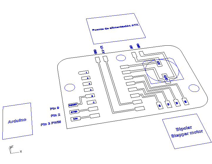
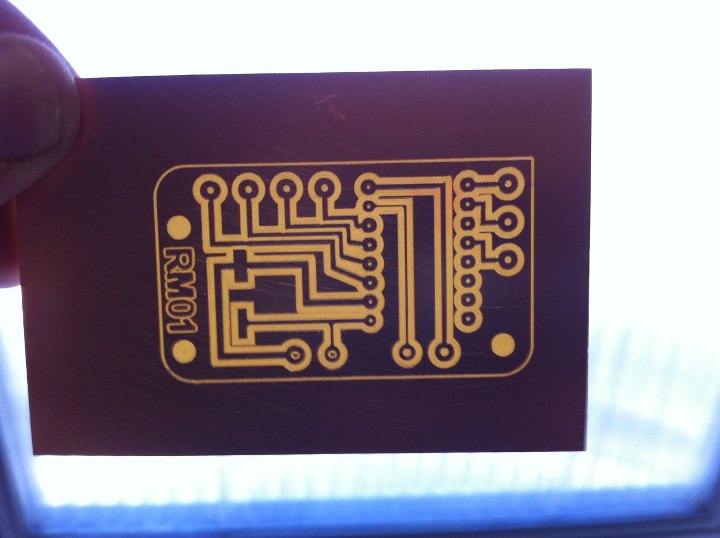
A schematic design was made with Inkscape, and then turned into the actual circuit design and milling files for the iModela with Rhinoceros; the file exported to the iModela, eventually was an ".ai", an Adobe Illustrator file, that can be generated from Rhino [see images and links to files below].
The board was milled with the iModela, using a 4mm [1/64"] end mill - eventually! - that we were able to use thanks to a special adaptor/connector supplied by Roland Spain at the Fab Lab Iberia founding meeting in Barcelona. Compared to the 45º mills we had been using all through the academy the results using the 4mm end mill were extremely good. The board combines smd [capacitor] with through hole components [connectors].
The intelligence, as mentioned, is run by an Arduino Uno. We tried to make it with our own fabricated Arduino, but after trying four times in the lab with hello Arduino and Fab Kit 2.0 we didn't manage to make it work yet.
A laser cut and etched 3mm MDF platform supports and gives stability to both boards. Both of boards are powered by the 12V battery - connecting to the Arduino through its own connector that i soldered too. The Arduino powered with 12V, regulates its own voltage, and provides the second board with 5V, through the 5V (and GND) pins. This allows for a single power source for all the system,- it is used to power a second Arduino in charge of the I/O system, too.
The system has been designed following the instructions in the Pololu web page and data sheet, as well as Igna94Igna's, a local young colleague, online instructions [and code].

Above the connection diagram provided by Pololu for the Allegro A4988 motor controller "step-stick".
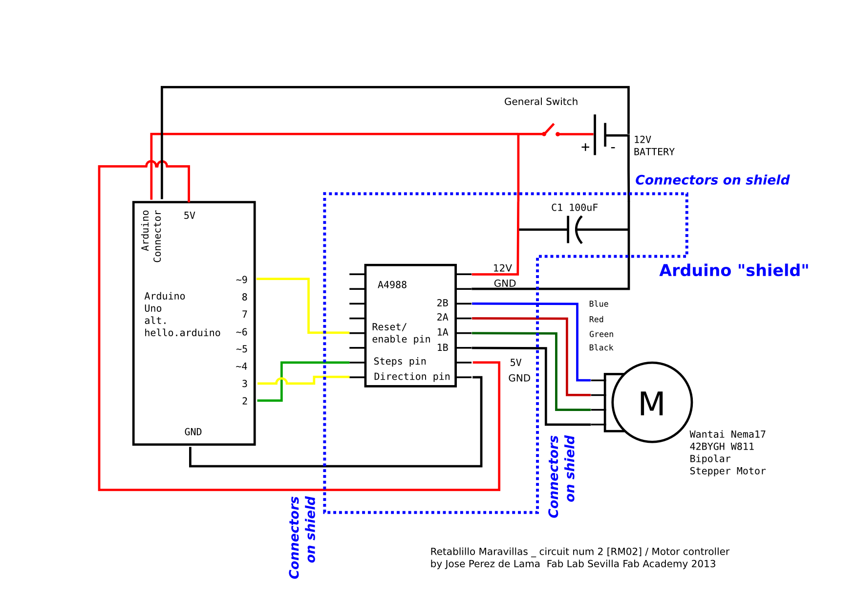
And this one is my adaptation of the Pololu / Allegro diagram [http://www.pololu.com/catalog/product/1182] to be used in my configuration with Arduino and a Nema17 Wantai bipolar stepper motor supplied by reprapworld.com [http://reprap.org/wiki/NEMA_17_Stepper_motor] - that i had used before for the Reprap Prusa i2 that we made in former classes during the Academy. A larger version of the above image can be seen using "view image" in Mozilla / Chromium. The additional connections and the recommended 100uF capacitor, plus the A4988 are set in a "shield" as seen in the following drawings and images.
Rhinoceros image captures for the motor controller PCB design and milling file:

Download Rhinoceros file >> download link | alt download link [without .3dm extension]
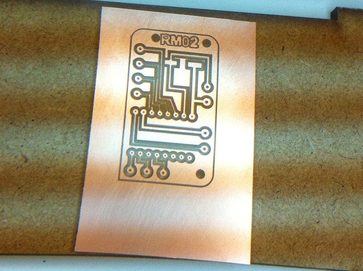
Milling was a slow process. Eventually i was able to mill with a 1/64" end mill - instead of the 45º that we had been using up to now - thanks to a special connector provided by Roland Iberia, and some mills sent to us by Nuria from Fab Lab Leon - thanks! -. The first board milled with the end mill came out perfect... But... I hadn't realize that because i was using through hole technique for some of the components, i should had milled it upside down... Before, in the first board i had made minor mistakes, while in the third board some tracks didn't come out well; so i ended up milling at least four boards until i got a truly great one... Here are some pics of the process:
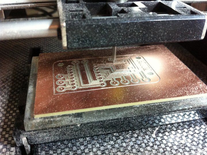
Above: milling the second board with the 1/64" end mill; perfect milling that i did unfortunately "upside-down".

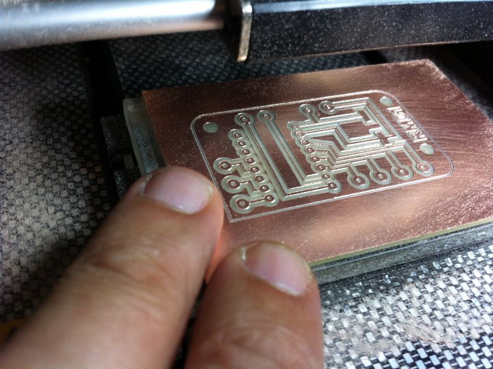
Above: First and second boards; board planarity and milling record; third board, symmetrical to the two first ones, but with some lost tracks. The holes were afterwords drill in three different sizes with a Dremel drill fixed to a drilling stand to get them exactly vertical.
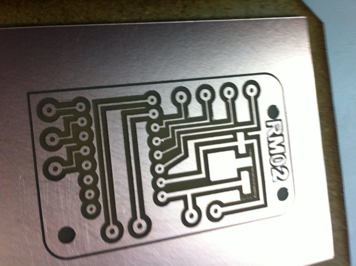
Above: This eventually, was a great milling. Some copper lines can be seen over the capacitor that i cleaned with en x-acto knife.

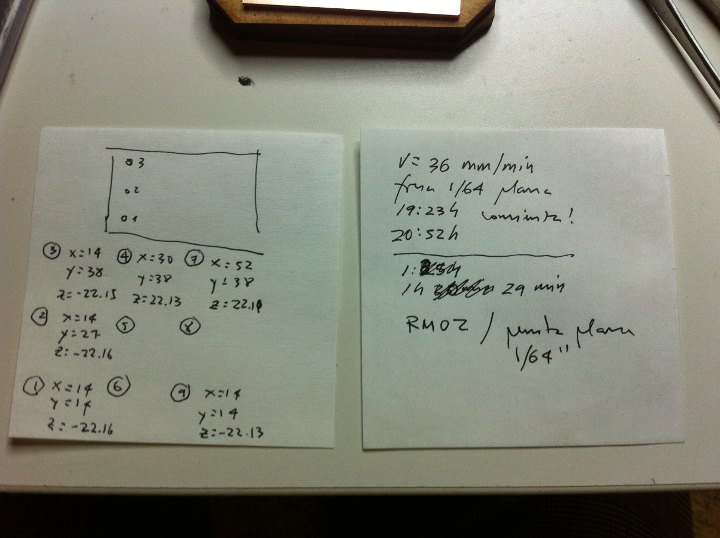
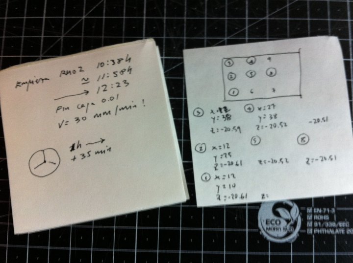
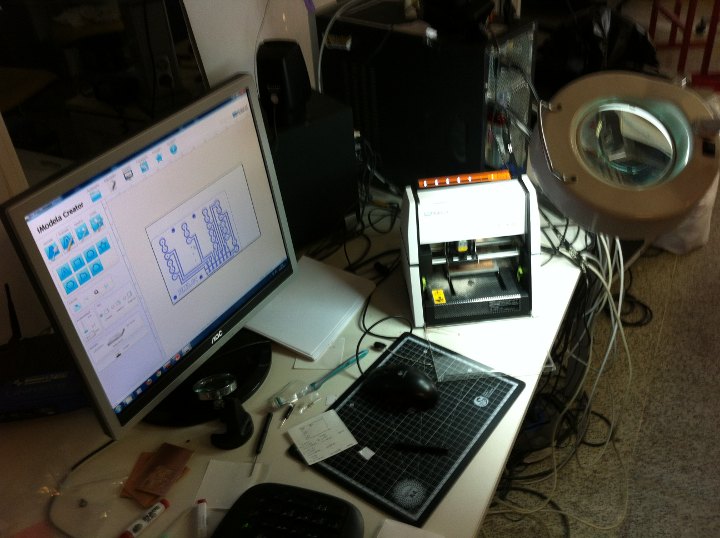
The milling set-up, with iCreator and iController software and iModela milling machine... and magnifying glass. Planarity calibration and time control notes. Milling was performed at a very conservative 36 mm/min speed; it took about 1h and 30 min.
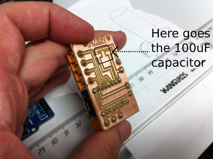
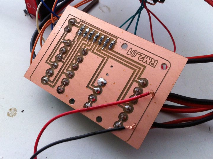
Front and back sides of the board. On the left, the smd 100 uF capacitor is still to be soldered. On the back side the female connectors provide a socket for the A4988 Pololu stick, while the orange connectors, clockwise receive 12V and 5V power, the three Arduino pin connections, and the four bipolar stepper motor connections. In a next development the board could be designed as an actual arduino shield.

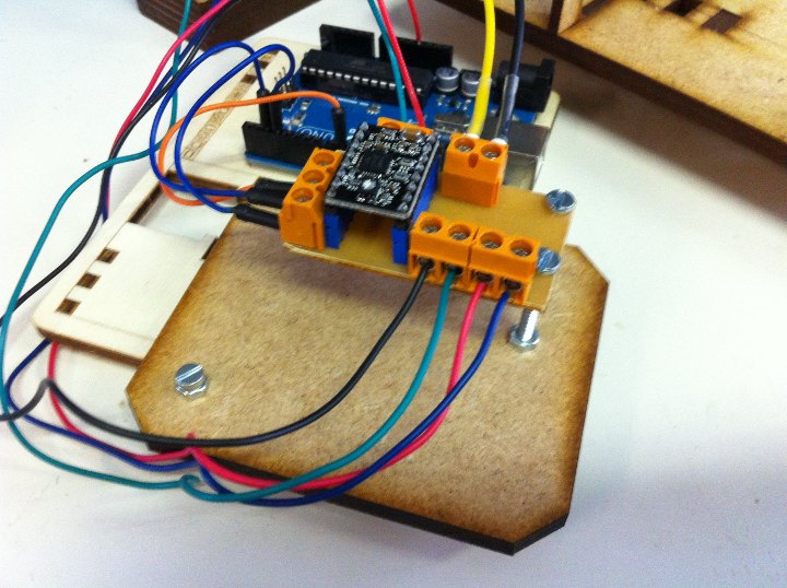

Above: The motor controller board connected to the Arduino Uno. I set it up on a provisional base with some nuts and bolts to allow for some space for the tall 100 uF capacitor. Below, testing the board with the actual mechanism and first program version. Follows link to a video with the first successful test: https://vimeo.com/72100330
After this i milled a board to fabricate the hello.arduino pcb. The results were rather poor, but even if it does look disastrous, testing the tracks with a multimeter it did give ok continuity for all the tracks. The pads for the microcontroller leads are, however too tiny, and i was a bit discouraged... The new 1/64" end mill had lasted us for fours or maybe five boards, which makes for 5 euros per board... So, being pressed with time i decided t moved on to designing the second of the boards that i still needed to make...
[4.4/ I/O controller boards]
A second pair of boards control the game start and end [game over] as well as the scoring display.
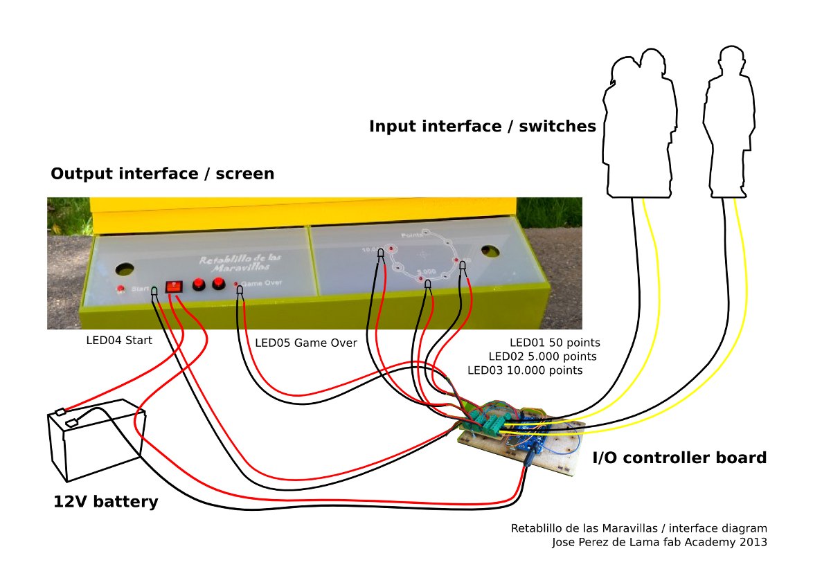
A second Arduino Uno runs this together with a secondary board designed and fabricated for the project. This second board, receives the signals coming from the switches made up by two characters on the moving platform [on/off signals whether they are standing on their place of have been knocked off], making three different LEDs blink, LED's that are associated in the screen to the different scores. Two other LED's controlled by the board and associated to a timer, performed by software loaded in the Arduino, are blinked at the start and at the end of the programmed game duration interval.
The board again combines SMD components, resistors associated to the switches and LEDs, with through hole components for the connectors.
Again a 3mm MDF laser cut and etched platform supports and gives stability to both boards.
This pack is again powered by the 12V battery through a [second] Arduino Uno connector.
The boards are placed in a compartment in the front part of the chassis, close to the motor and right below the screen. The battery is housed in a second compartment right below the one housing the electronics boards.
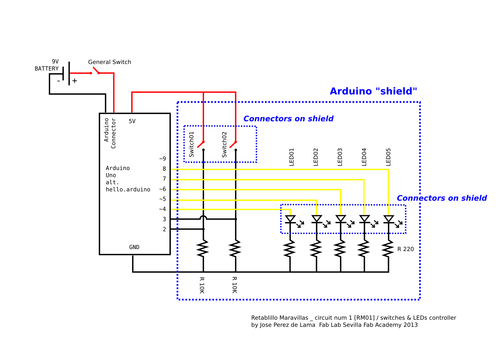
Electronics diagram, with arduino, auxilar-shield board and connectors to peripherical elements: Figures-switches, LEDs and 12V battery power supply.
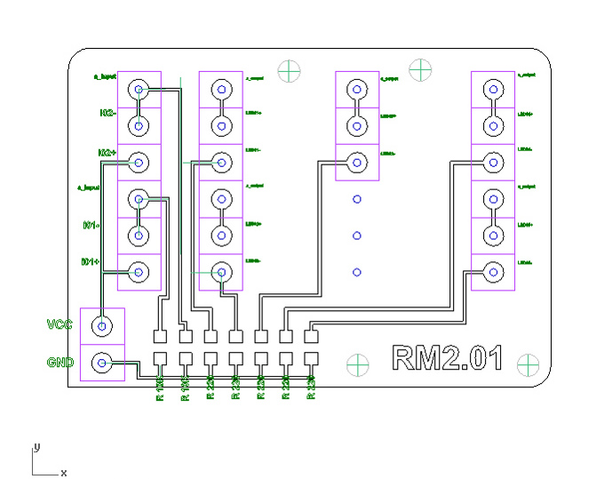
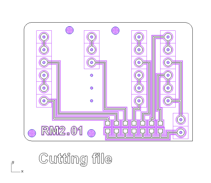

Three images above: circuit design with Rhinoceros; top image components, pads, tracks and holes; lower images; two tests for milling paths, with two and four offsets, after study of the 1/64" mill behavior. The actual separation between the first offest and the desired perimeter of the track i fixed in 0.36 mm. Rhinoceros was used instead of Fab Modules because of the ease of fine tuning manually these distances.
Download the Rhinoceros file >> 3dm file | alt download without extension
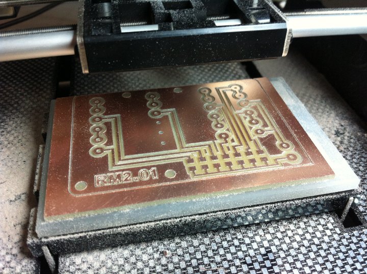
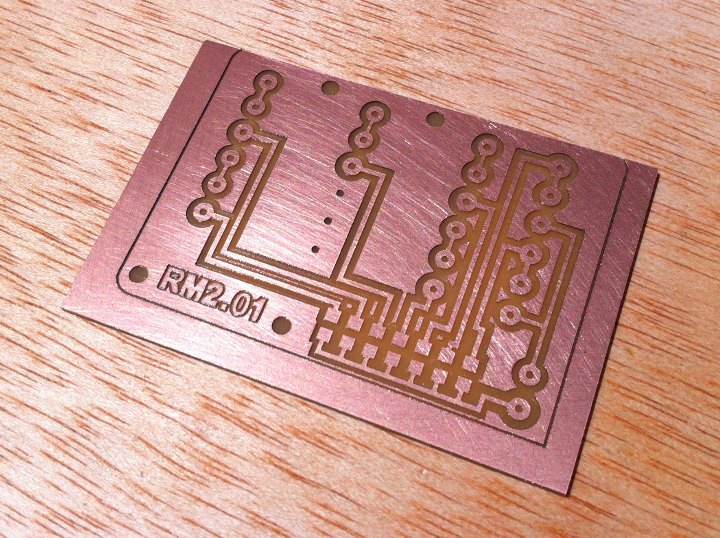
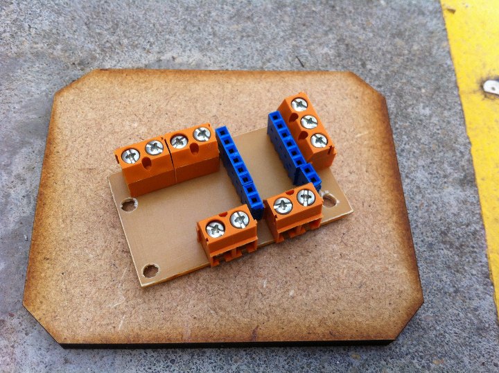
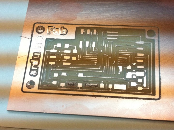
With a new 1/64" end mill i milled the second board, which came out quite perfect. The board is rather big, but here a relevant consideration was to have space to be able to make the cable connections with a certain ease. The board was eventually milled with three offsets.
When it came to soldering i realized i didn't have the 220 Ohm resistors that i had designed the board with. What i did, with the advise and help of Aureliano Gómez, was to solder to 499 Ohm resistors in parallel - that is on top of the other - as can be seen, more or less, on the 5 resistors to the right. We checked them with the multimeter and they gave perfect 249 Ohms resistance each. The connectors are soldered to the other side with through-hole technique. The holes were made with a Dremel, for the connectors and for the M3 nuts and bolts to fix the PCB to a board together with the arduino.
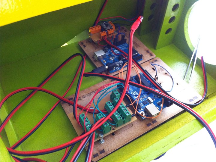

Installing the two/four boards in the compartment within the Retablillo. As can be seen the boards are bolted to two MDF boards laser-cut-and-etched, and equipped with little legs. The board in front was originally thought to incorporate a 9V battery, but then i realized i could supply 12V to all the boards and let the arduinos convert and supply 5V [LED circuits] and 3.3V [Pololu logic] when needed. In the second image there can be seen the two arduinos connected with their special connectors and to the common 12V power supply, that gives power too, directly to the Pololu 12V connection, in the far end. The black-end-red cables coming out from the first set of boards go to the LEDs and to the figure-switches. The arduino USB connectors were used to fine tune the programs, but are not used once the programs are set. The motor board is right below the actual motor making connections easy.
///
* "El Retablo de las Maravillas" is the title of a short story, “entremés”, by Spanish classic author Miguel de Cervantes, where he depicts a lighthearted while ironic story around a theatrical representation: http://miguelde.cervantes.com/pdf/El%20Retablo%20de%20las%20Maravillas.pdf
///
Unless otherwise stated, information in this page is downloadable under a Creative Commons Attribution-Share A Like license; attribution: Jose Perez de Lama / Fab Lab Sevilla / Fab Academy 2013. Work is based in the documentation provided by Neil Gershenfeld / Fab Academy 2013; and Anna Kaziunas, AS220 Fab Academy 2013; among other sources.

final project home / structure / mechanics / electronics / programming / all files
return home /perezdelama.jose