Fab Lab Barcelona SuperNode /Fab Lab Sevilla /Jose Perez de Lama
hello.arduino.168 example and tutorial / Part.05
[developed april/may 2014]
8./ Fabkit fabrication notes (files, BOM, ISP cables & connection)
Fabkit/Fabduino is a second version of the Fab Academy hello.arduino. General instructions to make it can be found here: http://fab.cba.mit.edu/content/projects/fabkit/
Here is an anotated version of the Fabkit layout image that can be found in the Fab Academy page, including the components values, ISP pins on the board and on the AVRISP sides. The main difference between Fabkit and hello.arduino is that Fabkit enables all but two pins of the ATmega 168 micro as input and output pins. You can easily see, that it includes two more capacitors than hello.arduino, that the value of the resistor associated to the LED is different, and that it doesn't include a jumper (resistor 0 Ohms). The two new capacitors are associated to the AtTmega pins 4 and 6 and the resonator's Gnd connector. I imagine this configuration smoothes voltage changes between these elements [?]. As in the hello.arduino board you have the option to make with and without the external 8MHz resonator. (BOM)
The process to make the Fabkit board is analogous to that of the hello.arduino board.
The original files this time are in Eagle format and you can download them from the tutorial URL: board and schematic. There are also png traces available, including one of them to mill holes for the connector pads.
This is a general Fabkit diagram remade after the Fab Academy site and some tips by Nuria Robles at Fab Lab Leon:

Again, i decided to generate my own traces and milling files, following the procedure and "design rules" presented above. I had milled some time ago a board with the available file and i felt i would prefer some more space inbetween the tracks, so i ended up enlarging the board a bit. Here is a Rhinoceros screenshot of my modfied board and links to the Rhinoceros and .ai files. You may appreciate that there is only a single line inbetween the microcontroller pads.
fabkit_rhinoceros | fabkit_ai

I decided also not to cut holes and use connectors similar to those used for the FTDI port, and find or make some female headers and attach them to cables that on their other end fit into the ISP "target interface".
The board was milled again in "two rounds" coming out quite well. (*) It looks a bit strange because there was a previous round of milling before the first that didn't cut at all but only marked the surface of the board, and i decided to re-use the same board but wasn't able to set the same 0,0,0 reference point...


This is my soldering set: magnifying lamp, solderting iron and stand, solder, vise and third hand, tweezers and flux.

And this the stuffed and debugged board. The right side got a bit burnt out cutting the board, but fortunately it didn't affect the tracks. Again i had to resolder 4/5 connections.
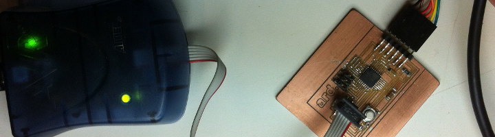
Now comes the part that had stopped us in the lab to finish this board for some time, that has to do with the ISP connection. The diagram showed above give the directions on how to make this connections (help by Nuria Robles at Fab Lab León on this was very welcome). First thing i had to do was fabrucating some connection cables as shown in the next image. I couldn't find the right connectors so i "bricolaged" them cutting some longer female connectors that we had in the lab and some soldering.

Then following the diagrams i made the precise connection between the AVRISP targer interface and the fabkit pins. I just used one more pin in the board and cable for the GND connection, to go for a simple solution.


Once everything is connected, the procedure is exactly the same as before (Arduino IDE...). And, indeed, it did work right away!!! To end the process i uploaded the blink sketch and here is a little video of the results: https://vimeo.com/94460845
Links
Part 01
0./ About this tutorial
1./ Description :: hello.arduino.168/328P
2./ Fab Academy reference files list and location
3./ Tutorials, info sources and URLs
Part 02
4./ Workflow & toolchain
Part 03
5./ System and software requirements & installation
6./ BOM (Bill of Materials) equipment and tools
Part 04
7./ Detailed fabrication process description
7.1/ Board preparation and milling
7.2/ Components soldering and debugging
7.3/ Bootloading firmware and uploading your first Arduino sketch (program)
Part 05
8./ Fabkit fabrication notes (files, ISP cables & connection)
jose_perezdelama @ Fab Academy 2013 final project
jose_perezdelama @ Fab Academy 2013 home page
Credits & license
This work is a derivative of documentation collected in the Fab Academy classes and tutorial pages authored by Neil Gershenfeld, Anna Kaziunas/AS220 and Fab Academy collaborators and students as mentioned in the corresponding linked pages for each of the sections.
Unless otherwise stated, information in these pages is downloadable under a Creative Commons Attribution-Share A Like license; attribution for the tutorial reorganization: Jose Perez de Lama / Fab Lab Sevilla / Fab Academy 2013(14).