Category Archives: Uncategorized

week16-applications and implications-shmulik bilgoray and douglas adams

Week 16 – Applications and Implications – Shmulik Bilgoray – Douglas Anderson

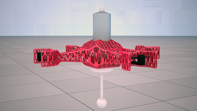
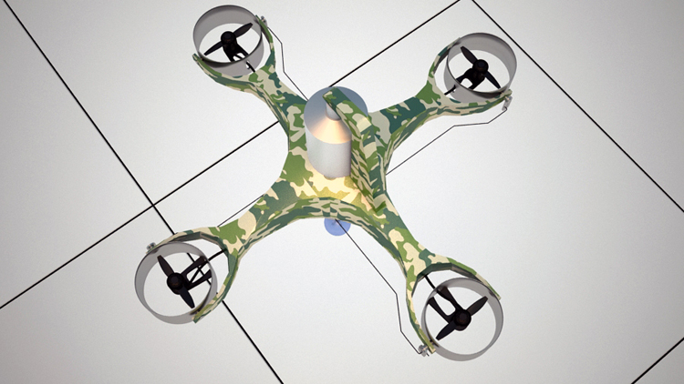
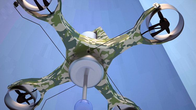
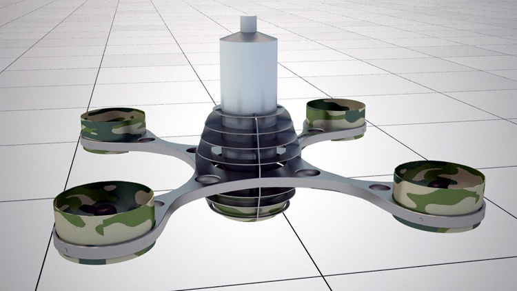
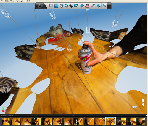
The project we are proposing is a flying hexocopter with a spray can and trigger mechanism mounted so that it can paint ˜graffiti art” on high walls. The final and ultimate goal is for this copter to fly automated on pre-defined draw-paths.

A preliminary goal for the project, particularly on the time-frame of the FabAcademy is to design, construct and test the spray and trigger mechanism. This includes the physical trigger mechanism with its motors, the control/driver chips (could be the hello bridge) and an input device. The input device may range from something as simple as a button or button on a radio transmitter (similar to a controller for the hexacopter) or to such things as proximity sensors, light sensors etc.

A further sub-goal is to construct the shop-bought Y6 hexacopter, mount the spray mechanism and conduct test flights.

Potentially, but not necessarily within the time frame, we may also be able to program flight paths initially with GPS waypoint plotting and then further develop a fine-resolution system for positioning and feedback adjustment.

Whos done what beforehand?

-Similar projects in existence:

While there have been projects developed dealing with automated graffiti art and numerous projects that deal with automated flying machines, no evidence has been found of projects that combine the two fields as is intended here. The success of this project has many implications for further projects that may utilise the technology for other purposes. Documented graffiti art projects include the Tag Bot

-Experience of group members

Group member Shmulik has had some experience with constructing and operating flying vehicles. Aside from this, this project is being approached with only the skills gained from the FabAcademy 2013 course.

What materials and components will be required?/Where will it come from?/How much will it cost?

What parts and systems will be made?

The Trigger Mechanism

The trigger mechanism will be made and will include a number of sub-systems:
The Mechanical trigger mechanism includes an aluminium structure, levers, pulleys and steel cable. The motors with be 12V DC motor with gear head ratio 100:1. The motors will be mounted onto the trigger support arm and will need to be driven by H-bridge boards (to be made). The H-bridge board/s may require additional control in the form of a Fabduino or similar that will interpret the input signal (sensor, button etc.) and transfer the output signal to the driver boards. We may choose to employ a signal transmitter and receiver board/s to remotely transfer this trigger input for the initial testing. This would allow a greater understanding of the final arrangement to be made.

Constructing the hexacopter

The shop-bought hexacopter will arrive in kit form and will need to be assembled. This process will allow assessment as to which parts may ultimately be replaced by custom-made parts
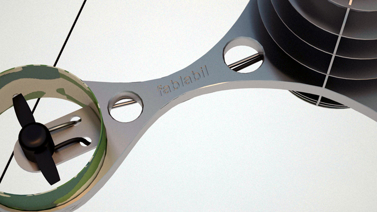
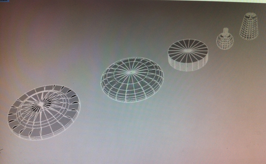
Propellor Guards

Propeller guards will be needed for flying in close proximity to walls or other objects and will be constructed during the following weeks.

Navigation System

A navigation system will ultimately be made for the flight path and spray trigger. This will be developed and potential methods explored over the coming weeks. This will undoubtedly include sensors and emitters providing input for a feedback responsive system, that will be capable of navigating with a precision sufficient to write legibly over reasonably small areas.

What processes will be used?

Numerous processes will be used during the construction and testing of the hexacopter. These may include but are not limited to the following:

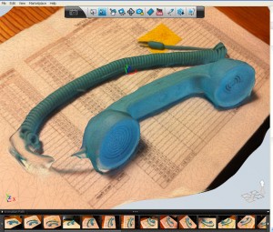
Computer Aided Design
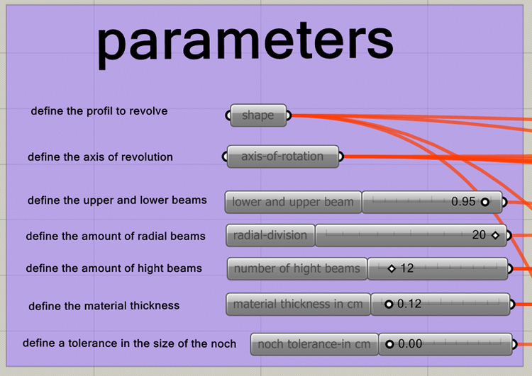
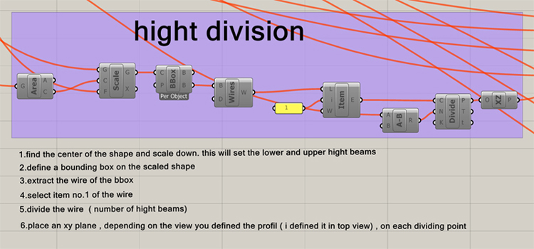
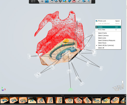
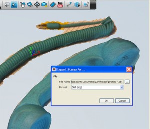
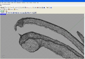
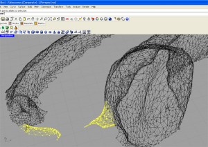
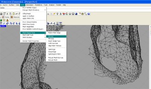
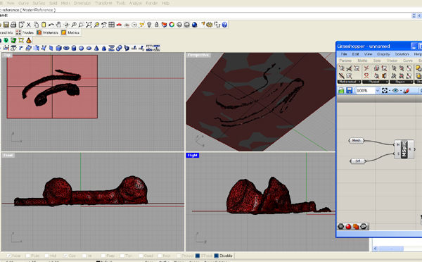
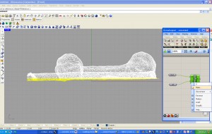
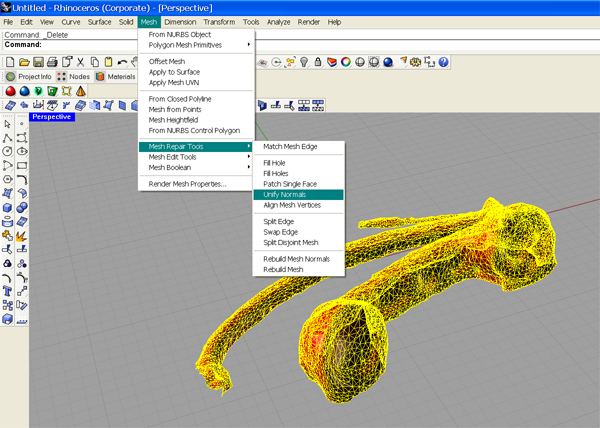
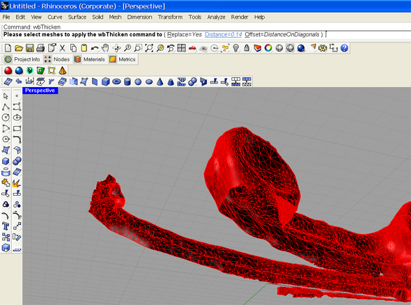
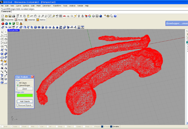
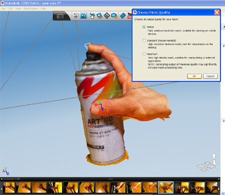
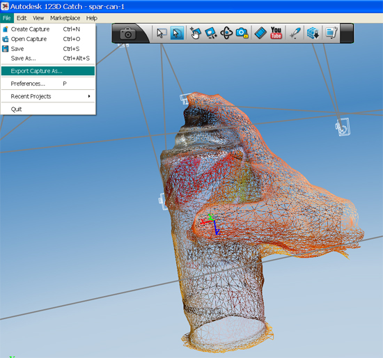
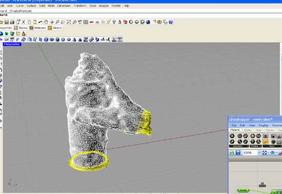
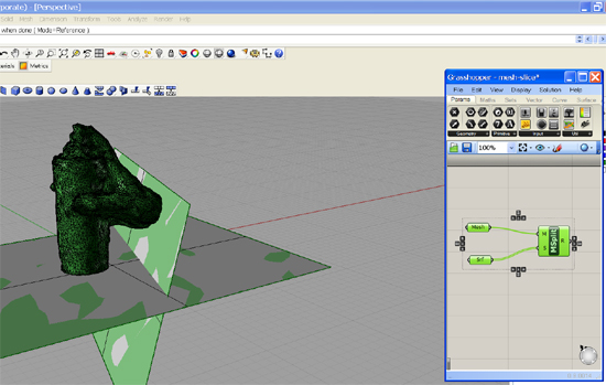
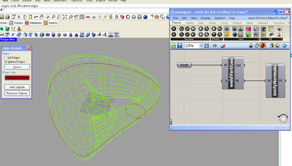
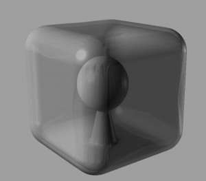
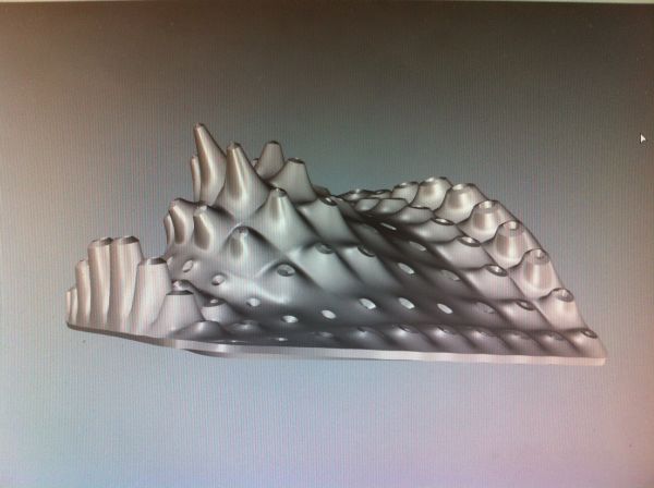
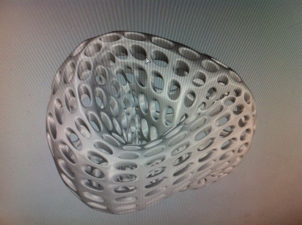
The trigger mechanism will be designed and modelled in both Rhino and eventually Solidworks for animation. The CAD files will be used to test various styles and sized eccentric arms that will provide the lever for the spraying of the paint can. The entire Copter will also be modelled and sliced in order to make a lazer-cut layered model for testing and visualisation.

CNC-Milling
The Aluminium components used in the trigger mechanism and structure will be milled from stock aluminium sheet and/or square tubing. This may be conducted on the shopbot and/or the Sherline CNC.

Electronics Design -
May be required in order to design and construct a signal transmitter and receiver board for initial set-up of the trigger mechanism.

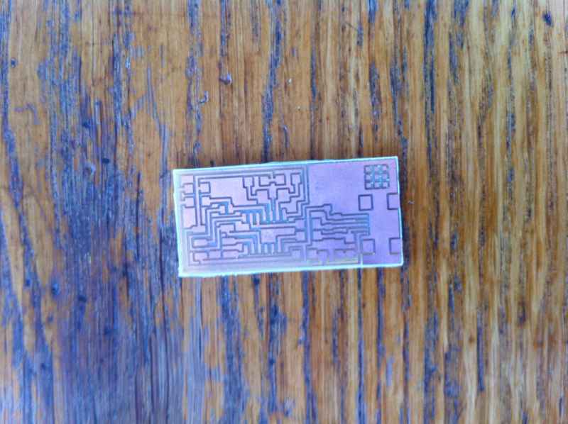
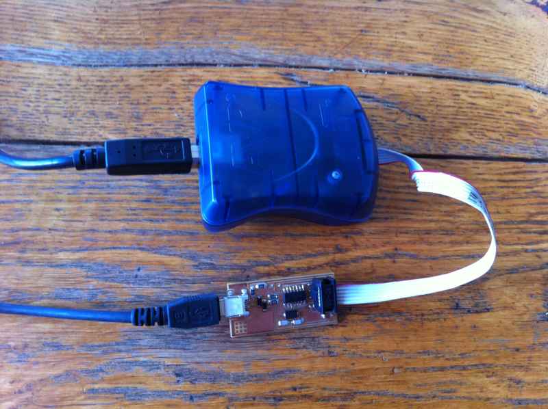
Electronics Production
Initially, there will be the requirement for electronics to drive the trigger mechanism motors, send and receive signals and potentially more to process the complex messages. The construction of the hexacopter will include electronics however this will rely on the shop-bought control chips for simplicity.

Embedded Programming –
Will drive the DC motors as a response to input signal/s.

What tasks need to be completed?

Assembling the Hexacopter kit
Test flight
Finalising design of the trigger mechanism and control system
Constructing the trigger mechanism and control system
Programming the control system
Designing and investigating the navigation system
Developing a method for transferring a vectorial 2D design into a flight path

What questions need to be answered?

What profile and dimensions of the trigger eccentric arm will minimise force required (motor torque) and maximise effectiveness.
Will the hexacopter carry the weight of the trigger mechanism
Will carrying the trigger mechanism affect manoeuvrability and function
How will the navigation system be designed and function
How can a 2D vectorial design be transferred into a useable flight path

What is the schedule?

Week 1 -

Assemble Hexacopter
Test Flight
Finalise Design of trigger mechanism
Construct trigger mechanism and control boards
Week 2 -

Programming the control system
Develop communication system and test input devices to trigger spray
Devise an electronics Packaging system for Hexacopter
Test mountig system for Trigger system on Copter
Test flight + test spraying during flight
Week 3 -

Development in positioning system
Deveolp/research mecthod for transferring design into flight path
Test flights with lED and camera to capture path

How will the schedule be evaluated?

Sub-weekly meetings and assessment of the completion/success/failure of assigned tasks.

week15-mechanical design

I this weeks assignment we had to build a group project.

we decided to make a 3d printer that prints caramel.

My part in the group project was to make a grasshopper code that wil take an object and slice it to layers that will be printed in the caramel printer.

Here is the code

week 1


The first assignment is to build a personal site describing me and my proposal for the final project.

I use “word press” for my site and modified the default template.

I also had to build a database on my computer so I used  xampp.

To have a static site i had to use a “sucking” program. first i use “site sucker” but it had some broblems with finding the csi file of my site so i switched to “httrack”/

http://www.httrack.com/


week 2-computer aided design


The second assignment is to build a 3d model of my final project.

a0013

in the last two week i searched the internet for project of flying things that can lift heavy weight.

i came to the conclusion that a quadrocopter  is the thing i should design and build.

i decided to build a flying drown that spray graffiti on walls.

things i have to solve:

1. weight issue.

2. stability.

3. some kind of gps system so my drown can navigate throw space to its target.

All these things have to affect the design of the drown. I tried to look into the mechanics throw my 3d model.

I built the models in rhino and rendered it in 3ds max.

a0000

in the first model i used weaver bird plugin to get the holes in the budy of the model. its for losing weight. but i can see that this is not the kind of construction i will be able to do in this fablab.


In the second model i decided to switch to layers a0003system to deal with the weight and heating issue. this structure is strong and light. it will also helps me to hide all the wiring  of the different parts.I also added cover for the rotor as a safety precaution.

the third model has a full body and some camouflage grafics on it. I made a material in 3ds max using        a camouflage bit map.

a0006a0008a0005a0007


in the last model i mixed up every thing – the layered structure, the rotor cover and the camouflage bit map.a0009a0012a0010a0011

I don’t like importing rhino models into 3ds max. when i convert the n.u.r.b. model into mesh model i get a messy and complicated mesh and the textures doesn’t fit well.


week 3-computer controlled cutting

this weeks assignment was to design , make and document  a press fit kit.

c0I used rhino and grasshopper to build a wafer structure of a revolution of a profile. I wrote a code in grasshopper so i can easily experiment different shapes and profiles easily.

c1


Here is the code

grass1

grass2

grass3

grass4

grass5

grass6

grass7

grass8

The code bulb.gh

After selecting the profile, I exported the file to an *ai and sent it to the terminal of the lazer cutting machine.

c7

b1

The next time i use cardboard as a material i will make the noch two tenth of a millimeter bigger then the thickness of the material.

week4-electronics production

This weeks assignment was to make the fabisp.

I downloaded the .png files of the board and milled then on the sherline.

hello.ISP.44.traces hello.ISP.44.interior

IMG_5268

I soldered the components.

IMG_5270


I downloaded and installed winavr.

I downloaded the usbtinyisp files.

Go to the Start Menu > Hardware and Sound. A “unknown USB device” should be listed
- Right click on the “unknown USB device”
- Select “Properties”
- Select “Hardware”
- Select “update device driver”
- Select “choose your own”
- Navigate to the drivers folder you downloaded to the desktop and click on the folder.
- Hit “ok” to install the drivers for the USBtiny / FabISP

I connected the fabisp and the avrisp together and to the computer via usb cabel.

IMG_5267


This is from the providence tutorial

A window will open containing the Makefile. Go to the line that says:
#AVRDUDE = avrdude -c usbtiny -p $(DEVICE) # edit this line for your programmer
AVRDUDE = avrdude -c avrisp2 -P usb -p $(DEVICE) # edit this line for your programmer

- If using the USBtiny programmer or another FabISP
- Remove the “#” in front of the line with “usbtiny” in it
- Add a “#” to beginning the line with the “avrisp2″ in it to comment it out.
- save the Makefile

Navigate to the directory where you saved the FabISP firmware. If you followed the instructions above, this will be the desktop.

Open your  command line interface and move to the firmware directory.

I followed the providence tutorial and programed the board to be an isp.

After that i cut the jumpers so it can be a programer.

week 5- 3d printing and scaning

This assignment was to 3d print a model with our riprap 3d printer and 3d scan using one of the free software available on the web and a camera.

3d scanning

 For scanning i use 123d catch by autodesk. it is very easy to install and there is an app for the i phone.

1

I took pictures with my i phone and loaded them into tje software for calculation. it is very important to have a good light from all over the object and he has to be in focus. if not, the mesh will be deformed and will have holes in it. i found that natural lighting, especially in the early morning or in the evening gives the best result. it is also important to have a noisy back ground which helps the program to stich the photos together.

I took about 40 pictures of the object from different angles and loaded then.

after a short time i got an e-mail with a link to the model. i changed to mesh view so i can clean the model from unnecessary parts.

23


After i finished cleaning the mesh, i exported it as an .obj file so i can import it into rhino.

5


4

In rhino i  continued to clean the mesh from small attachments and close the hole with “close hole” command from the “mesh” menu.

8

9


10


I want to try and print this model so i continue on playing with it. i split the mesh with some planes so i can get get a clean  cut in the “ends” of the model.

11

12

I used “unify normals” and “weaver bird thicken” ( a free plugin for rhino) to finish the modeling.

1314

I check the mesh for naked edges.

15

Then i exported it as an .stl file.

16

That was the part that went by the plans…

To print the model i have to get a gcode of it. I used slic3r for that. the first time i open the software i had to define the values for the printing process depending on the printer i use.

when i loaded the file into slic3r, i got a message that i have holes in the mesh. I checked the .stl file for naked egdes but didn’t find any. Again to slic3r and again that message…

I uploaded the .stl file to netfabb.com  and got the file fixed. when i loaded it into slic3r it was working properly. Now i have a gcode and the file is ready for printing.

I played with the 123d catch for some time and got also this model:

s2s1

s3 s4

and also loaded into rhino for preparing to 3d print.

s7 s6


Then i 3d print it

4

3d printing.

The question is: what  to print in 3d ???

1. I down loaded a free software called k3dsurf. It generates  3d  models based on mathematical equation.Clipboard01                                                                                                                                                                I played with the parameters and saved the models as.obj file.

2 1

the problem is that the models generate with a naked egde that has to be fixed. If not, you don’t know what the the 3d printer will do with it. It doesn’t read correctly the file’ don’t know if the face is facing inside or outside…it will be a mess…My “klein bottle” broke during the printing process.

Picture 008 Picture 010 Picture 011image


I fixed this issue with a simple code in grasshopper

t

2. hollow models withs-cube something insidevoronoi1 

3. complicated surfaces

voronoi-ring 3 Picture 009

I didn’t manage to 3d print any of the above. I hope i will do that tomorrow.

Last year i attended a short course in generative jewelry design. We used ” I-ring” and “paracloud gem”, two parametric softwares designed by architect Eyal Nir.                                                                             The I-ring software is an application for Ipad  that helps you to design a ring from scratch and send it to be 3d printed.                                                                                                                                             Paracloud gem is a software that helps you mount 3d element on a parmetric surface.

image3 image4

In that course we used a 3d printer making wax models for casting. The resolution is high and the product is very accurate.

Picture 002 Picture 004Picture 005


we also used a 3d plaster printer for less accurate models

Picture 003 Picture 001

image 2


week6-electronics design

This weeks assignment was to add a button and a LED to the helloweEcho bord.

I added the components in eagle in the schematics view, placed them in the board view.

Here are the files

2 1

I exported the board view to *.png file. first the traces and then the border.

helloweEchoShmulik-out-line helloweEchoShmulik

I generated a g-code in the fab moduls.

I etched the board in a sherline milling machine. The program we used is called EMC2. it reads *.ngc files so we changed the end of the g-code file manually (*.g to *.ngc).

Finally i stuffed the board with the components.

3

week7-molding and casting

This weeks assignment was to make a mold and cast something.

I decided to cast a shot glass from ice. for that i had to make a three part mold.I started with rhino and modeled the mold

milling 010

milling 011


I milled the mold from casting wax using the Shereline 5410 for the first two parts and the Shopbot for the third part  generating the .png files and g-code with the fabmoduls. I used 0.5 overlap of the milling bit. To get a better resolution and a smooth surface it is recomanded to use 0.5 overlap.

.png files

fab_mod_GLASS12_fixed   fab_mod_GLASS11_fixed

g-code

fab_mod_GLASS12_fixed.path  fab_mod_GLASS11_fixed.path

Milling with the Shereline 5410

milling 001milling 002

milling 003milling 004

milling 008milling 009

Milling with the shopbot

milling 005milling 006milling 007

After cleaning the part of the mold with Aceton i mixed silicon and poured it into the mold to create the mold for the shot glass. It take 24 hours until the silicon is completely dry and the i put it in the oven for two hours in 80 deg. C and another hour in 100 deg. C.

milling 014milling 013

The mold look a little bit to flabby-the “walls” should be thicker. i did them 5 m”m thick and i think they should be 10 m”m thick.

The design of the mold was two delicate. I thought the bit i used ( 1/32 inch v mill) will do the job…

I tried to place bits in the mold to close the parts together but they were to small ( 1 m”m radius is not enough).

After i took the mold out of the oven and tried to assemble it together i saw that the two sides of the mold don’t connect together very well and the water i try to put in spill out.

my conclusion is that the way i designed the mold isn’t good for casting water. I should have made the main part from one piece. Assembling it together doesn’t hold water.

casting 002 casting 003 casting 004 casting 005

After one hour in the freezer

ref1 ref2


week8-embedded programing

This weeks assignment  was to program the board we built 2 weeks ago.

I downloaded and installed Arduino.

1

I downloaded the FTDI drivers

2.

I connected the FTDI cable and installed it with its drivers.

In the Arduino software i go to the preferences and find where is the sketchbook folder.I navigated to that folder   and opened a sub folder in it called “hardware”.

I downloaded the ATtiny Board files and  unziped them to the hardware folder.This is for Aerduino recognize the ATtiny.

When i restarted Arduino i saw the ATtiny family in the tools>board menu.

I conected the fabisp and the button board.

IMG_5223

I selected the ATtiny44(external 20 MHz clock)

IMG_5217

. Then in the tool>programmer menu i selected USBtinyISP.

IMG_5215

then the serial port.

IMG_5216

From the tools menu i selected “Burn Bootloader”.

IMG_5214


Go to File > Examples > 02. Digital > Button Provides a code example for programming the LED+BUTTON.

I changed the constant intager of the button pin to 3 and the led pin to 7.

IMG_5220


Then i change the result of the led when the button state is high.

IMG_5218 IMG_5219

after uploading i got this massage.

IMG_5221

I also added delay to the code.

IMG_5225