The goal of this project is to design compute and build a flying robot that can paint with a spray can on a wall.
To preform this task, the robot has to fly, position him self in 3d space and carry out a pre planned move during coordinated operation of the mechanism clicking the spray can.
For this project i joined douglas anderson my peers, and between us we divided the project into two sub-projects:
1. planing the flying robot and his positioning system, which i was in charge and it will expand further.
2. planing the clicking spray mechanism that will work coordinated with the movement of the robot, which doug was in charge.
I searched the internet and looked for similar projects, what exists in the flying machines field and consulted with several experts and people who fly helicopters as professionals.
here are some examples for the things i found in the internet:


I decided to use some kind of a helicopter in the formation of a quad/hex/octocopters as these are very stable machines that use flight stabilizers.
I did some drowing and modeling to look for the right shape. i model in Rhino and render in 3ds max.
Here are some examples:


then i build the first model from birch wood an card board which i cut in the lazer machine.


I decided to form a “X8″ shape for the next model. it has 8 d.c. motors that all toogether create 8 kg lift force. This shape can allso keep the spray can far enough from the wind the engines make.


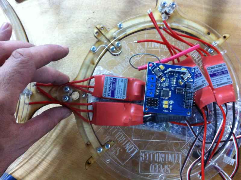
i also made a model for this design, cut from birch wood and perspex in the lazer cutting machine. This time i checked the place needed for the electronic parts of the X8.


I placed an order for parts for the X8 in the web site of “hobby king” and got the parts’ after almost 4 weeks…
Now i can design the the final model.


Here are the files of this 3d model:
These are photos of the model for the landing gear.

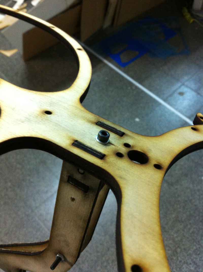
this is a test for mounting the parts on the model.
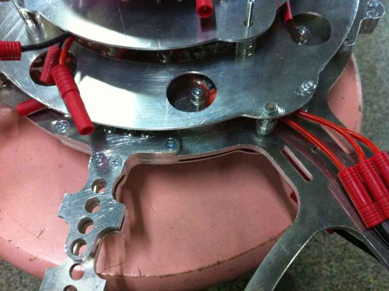
I decided to make the model from aluminum 6061 in the width of 4.06 mm, 1.6 mm and 1.01 mm, perspex and birch 4 mm wood.
we milled the aluminum with the shopbot, using 1/8 inch , 1/4 inch , 2.5 mm and 3 mm flat end 2 and 3 flout bits. it turned out that the 1/8 inch and 3 mm bits did the cleanest job with this material width. The milling was really difficult because we had no experience with this material. we broke some bits and lowered the speed of the movement of the shopbot until they stopped breaking which resulted in a long milling time.


After the milling expirience my conclusion is that the aluminum should be more hard as in the 7000 group. (like aluminum 7075 which is in the use of the air craft industry and cost twice the price per kg).
Assembling.


A video of the test flight:
Electronics
In the time frame of the course, i made the input and output system based on 3 IR leds and a Wii camera i took a part from a Wii remote.

The Wii camera can input up to 4 IR leds and output an x and y information about their position.


the tests i made with the camera showed me that the range is at list 10 meters and the angle is about 35 degrees horizontal and 25 degrees vertical. the right led for this mission is one of 850 nanometer .


another part of the project is to identify the different led.for that i used the simple code of blinking from arduino. i changed the delay time for each led and i will use manchester protocol to distinguish between them.