Final Project - City Factory
City Factory toured around Lodz, Poland thanks to the Muzeum Sztuki in Lodz and the ING Polish Art Foundation from May 20-26, as winner of the "Common Project" competition. That means that I had to be done with planning the project before I left for Poland on May 11! You can read about the project concept at the link above and on the proposal page; here I'll focus on production.
Model:
The key components are:
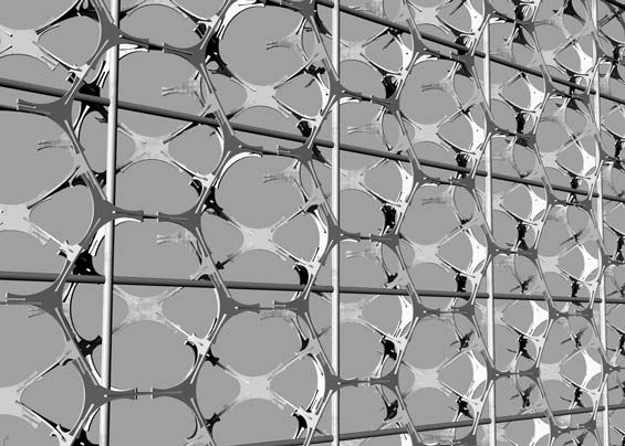
1. modular walls made of two repeating pressfit plexi pieces and a stabilizing trellis (they have to be sturdy enough to be movable on the truck)
2. LED lights that react to sound in the space and outside.
The table pictured (design needs some refinement) will be pressfit cut of wood, and the chairs and a few other pieces are readymades selected from common designs found in Poland. The touch pad clock-in mechanism has been removed to focus on the two components above. Instead, a simple egg timer stamped with "Time for Nothing" will be wound and given to each 'worker' who enters according to the time they wish to spend in the factory.
1. Walls
The math here took a good part of the spring to figure out.
I started out with a 3-legged piece, an equilateral triangle with 120-degree angles. Initially, I tried it as a mold (see my Molding and Casting page), with the idea of connecting PVC tubes to the mold to build the structure. This had too many variables though, and I didn't want to have to make the zillion molds after seeing how many places there were to make an error in getting the perfect fit.
I moved on to pressfit construction, and decided to make a tesselating pattern. That 120-degree anlge worked with cardboard (see my Make Something Big page), but the angles are actually not correct. With plexi and even wood, it became apparent that another piece was necessary. I added a 4-legged piece, and have gone through iterations from 60/120 angles, to 75/105, and finally settled on 109.47122 - 70.528779 thanks to Michael Rule's committed math help! I think the closest shape to what it makes is a honeycomb of tetrahedra and octahedra, based on these dihedral angles (angles at which two faces meet).
Here's the trail of evolution:
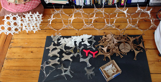
Tempting, but wrong:
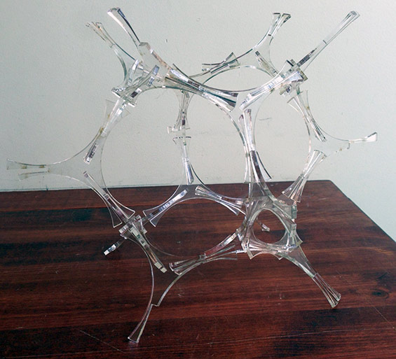
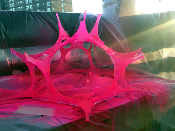
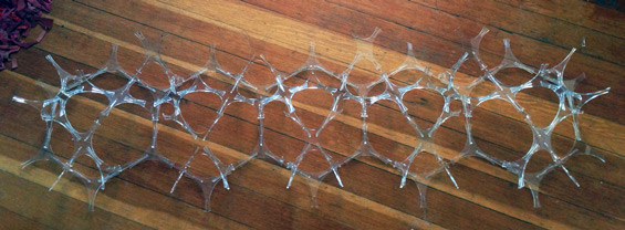
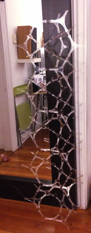
I have countless 'broken legs' from this process, as you can already see in the image above. The final decision is to print these somewhat loosely to make putting them together possible, and use a welding glue at the end to make it one solid object. The final shape appears like a half-dome, so that from inside the truck you see hexagons (half of the shape) and the rounded edge faces outside. I experimented with pink, clear and white, and the final shape will be white or translucent. There will be 8 of these 'half-domes' per column. Below is a column of 5 each for a test, glued with superglue. Seems pretty sturdy! I'd love to make them true pressfit, but the fragility of the plastic makes it pretty much impossible to connect the last pieces, so we'll do the looser print and use glue as an aid :)
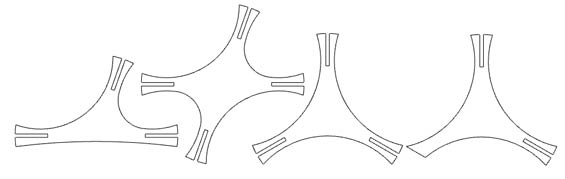
 There are really 4 shapes in the end, to account for the flatter edge facing inside, and the flat-edged bottom pieces:
Totals:
4-legged flat = 620
4-legged = 577
3-legged flat (stands flat on ground) = 38
3-legged = 1675
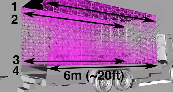
grand total of pieces times 2 = 5820 for both walls at 20ft w x 8ft tall
We have to print about 10% more, so 6,402 pieces total.
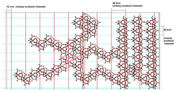
The lattice wil be wood or welded steel, and will relate to the pieces something like this:
2. LEDs
The LEDs will be used to light the walls along their top and bottom.
There are 4 strips of RGB LEDs at 20m each.
They will be controlled by our Arduino, and will pulse on and off in response to a mic suspended in the space.

There are 4 strips of RGB LEDs at 20m each. I'm using these LED's, which have 60LEDs/meter, for a total of 1,440 LEDs (360/strip). According to the stats available about the LED's, each drives .02 Amps, for a total of 28.8 Amps for the whole 24 meters (4 x 6 meters). Also, since there are 3 LEDs/1 in an RGB LED, I thought I needed to multiply this total amerage by 3 - but these stats don't take that into account. What's the right way to calculate the total power needed?
To figure out: how to connect these LED's to run off one of our Arduino's, and how to split up the power supply. The 5m strip that Amazon sells comes with a 5 Amp supply - is it possible to connect all of those through our Arduino? Or do I need several?
///
UPDATES
I think I can use 2 arduinos for the 4 strips. Each MOSFET can pass up to 16 Amps of current, so I can put 2 of each color on a MOSFET. Hm but the Arduino has 6 pwm pins, so maybe I could get away with using 1, and two sets of RGB pins.. Either way, that might get tricky physically, as each strip is 2-2.5m from the other on the truck. I had some troble getting readable values from the electret mic, so ordered a pre-amped one that's coming tomorrow (Sat). For now, I used a motion sensor to begin to figure out the code. Here's what I've got:
LED RGB 5m strip controlled via PIR sensor connected to a self-made arduino from Kate Balug on Vimeo.
2a. Mic to modify LEDs.
The goal is for the lights to be mostly on, and to flicker on and off in response to loud sounds heard from inside and outside the truck.
For tests, I'll use the equivalent of the basic mic that we've used in our boards, (this Radio Shack version), but need to do some more research on the one appropriate for this use. A friend used this mic for this rad project successfully, so I may just use that. This adds to the power load need - how do I connect this additional component?
UPDATES 2. POST-PROJECT
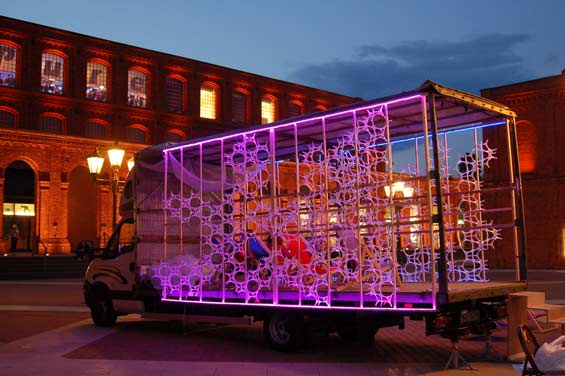
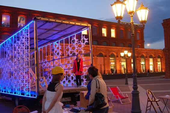
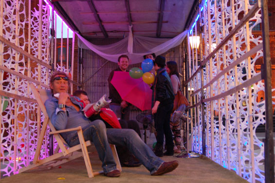
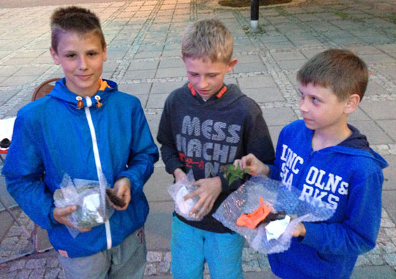
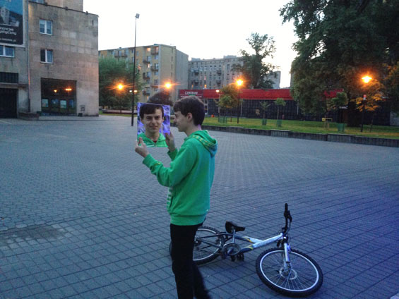
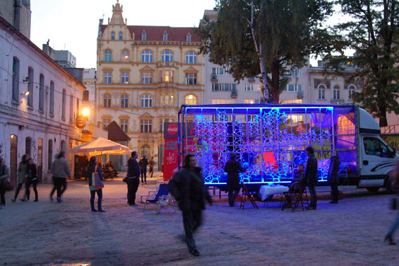
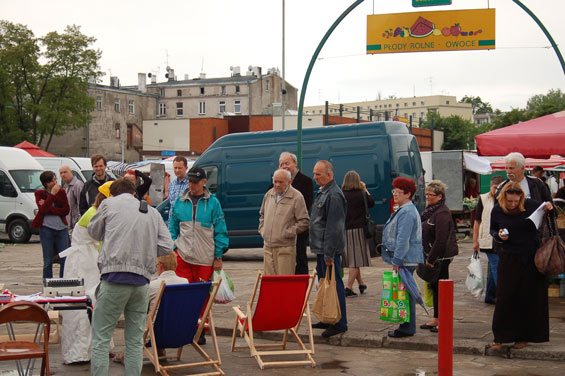
The 7-stop tour of the project just finished on Sunday! Once it went into the street, the fabbed components were a backdrop for a series of social engagements and a 2-hour nightly 'happening' with 17 unproductive exercises for volunteer workers from the public. We went to 7 diverse sites in this post-industrial city (often compared with Manchester or Detroit), sites designed for maximum productivity, be it labor, rest, or consumption of goods. Each sites had a very different atmosphere depending on its context and population - from the expensive new mall to the fruit and vegetable street market, to the first modernist housing blocks, to the former factory housing now occupied by the unemployed. We gave away 'time for nothing' to the public, who became City Factory workers for a few minutes at a time. People played with balloons, lost their partners' reflections in the mirror, and made soundtracks for the current moment out of bubble wrap, among others. It's too soon to respond to make any intelligent summary of what happened in the project, but I can say that it was tons of fun, difficult, and I think many people got something from it. The team in Poland was amazing to work with, and was super engaged, so overall the experience was incredible. My family, half of whom comes from Lodz, went to see the project almost every night, so it was the first time that my art was a family affair :) My boyfriend Nick and mom also came from the US, and Nick did most of the documentation seen here.
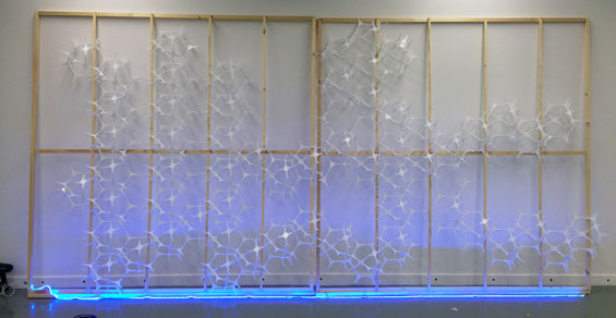
The plexi cost more than expected, so we were only able to print 1/3 of the walls. The final image was this - can you tell what it is? The grid was made of wood, and the plexi was zip tied to the wood, and at a few points drilled right into it.
The final prep of the LEDs:
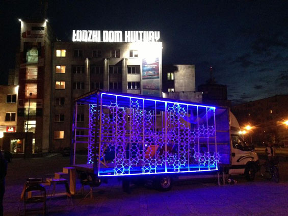
The lights are mostly blue, to counteract the red brick of most of the sites we went to. They switch to pink (the new red!) when a high pitched sound is picked up by the mic in the back of the truck. Here's the code:
int sensorPin = A0;    // select the input pin for the mic
int sensorValue = 0;                   //variable for reading the pin status

#define REDPIN 9
#define REDPIN2 6
#define GREENPIN 10
#define GREENPIN2 11
#define BLUEPIN 5
#define BLUEPIN2 3

#define FADESPEED 1         // make this higher to slow down

void setup(){
  pinMode(REDPIN, OUTPUT);      //declare LEDs as outputs
  pinMode(GREENPIN, OUTPUT);
  pinMode(BLUEPIN, OUTPUT);
  pinMode(REDPIN2, OUTPUT);      //declare LEDs as outputs
  pinMode(GREENPIN2, OUTPUT);
  pinMode(BLUEPIN2, OUTPUT);
  Serial.begin(9600);

}

void loop(){
  sensorValue = analogRead(sensorPin);
  Serial.println(sensorValue); // send it to the computer (as ASCII digits)
  int r, g, b;
  if (sensorValue > 100) {            // check if the input is high pitched
    // fade from blue to violet
    for (b = 255; b > 100; b--) {
      analogWrite(BLUEPIN, b);
      analogWrite(BLUEPIN2, b);
      delay(FADESPEED);
    }
    for (r = 0; r < 256; r++) {
      analogWrite(REDPIN, r);
      analogWrite(GREENPIN, r);
      delay(FADESPEED);
    }
    for (r = 255; r > 0; r--) {
      analogWrite(REDPIN, r);
      analogWrite(REDPIN2, r);
      delay(FADESPEED);
    }
     for (b = 100; b < 256; b++) {
      analogWrite(BLUEPIN, b);
      analogWrite(BLUEPIN2, b);
      delay(FADESPEED);
    }

      Serial.println("Noise!");
  }
  else {
      int i;
    for(i=0;i<100;i++)
    {
      digitalWrite(REDPIN,0);
      digitalWrite(REDPIN2,0);
      digitalWrite(GREENPIN,0);
      digitalWrite(GREENPIN2,0);
      digitalWrite(BLUEPIN,1);
      digitalWrite(BLUEPIN2,1);
      delay(1);
    }
    }
}
This code is borrowed from Adafruit's RBG LED strip fade tutorial and slightly modified to work with the mic.
Notice that the green pin is called out in the fade to red above. That's because the traces on my arduino ripped, so I had to rereoute the green pin to send a 'green' signal. This was the fastest way to do it on the fly.
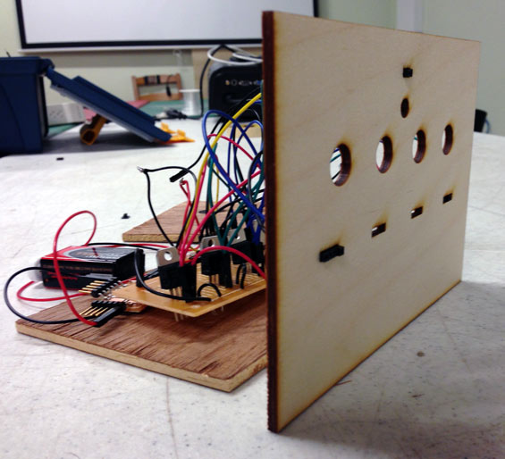
I was able to use just one of our fabbed arduinos, though I had to swap it during the week when another trace ripped. The electronics sat in a box I made of leftover pieces of board and a lasercut front to make the connections a little neater. On top of the box was a small fan because the mostfets managing the blue LEDs would get super hot. Everything ran off a 750 watt generator except for the arduino, which ran off a 9v battery. There were also three fans on the truck to help with a balloon exercise, so we had a lot of extension cords running on the platform!
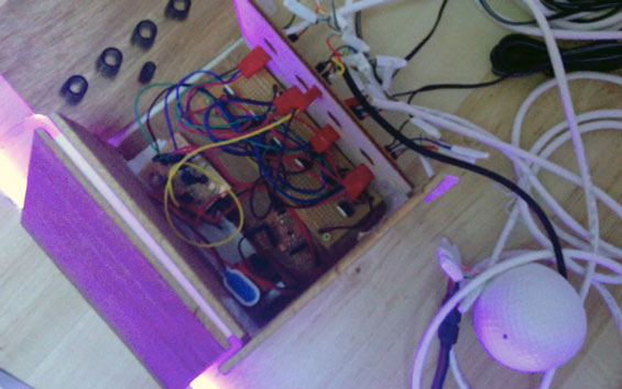
The faceplate, with 4 notches for each of the 4 strips, with outs for rbg and ground (these were common anode RGBs, power connected directly to the power supply, and this ground connected to the ground from the power supply). The round holes were meant to help circulate air. The top notch is for the mic - with the input and ground connections (it ran off a 12v supply like the LEDs, so I'd plug it into one of the LED power strips).
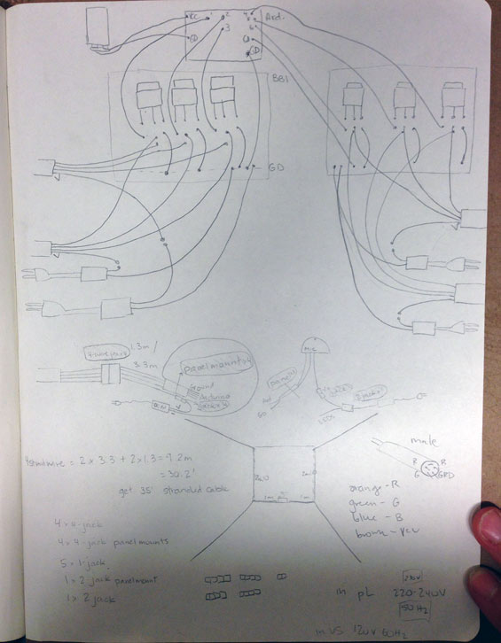
and my handmade fritzing diagram for how it all connects:
A test of the lights:
Final Code from Kate Balug on Vimeo.
This is how it all came together:
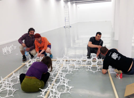
Installation with the amazing team in a gallery at the museum:
First wall:
and a very important test with the awesome museum preparer: DEER WALK
Some pics from the events:
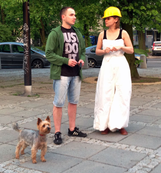
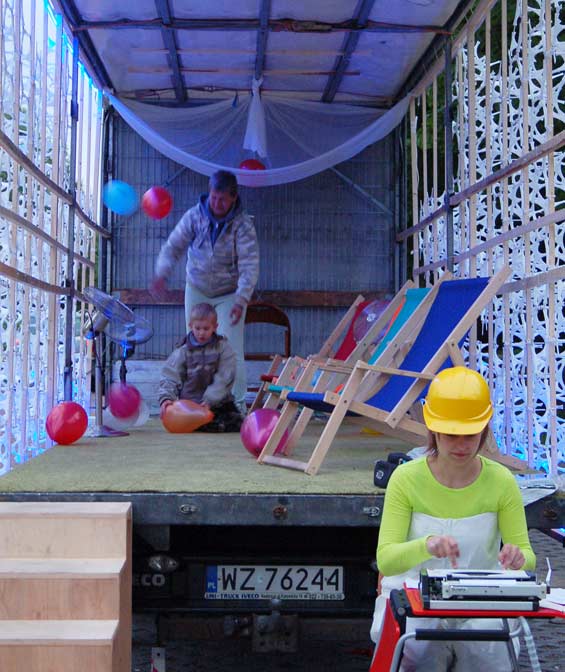
Me, in costume, talking to a potential factory worker. Costume by my talented friend Julie Goldstein. Made of painter's coveralls, it had a full on dress inside for structural support! We painted it white before taping it all together. Yellow helmet (it's a factory!) and very typical Polish slippers.
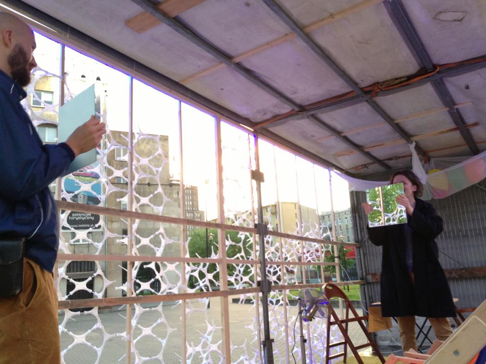
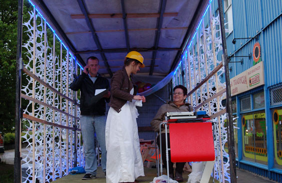
The factory in action.
Exercise 114: walk away until you lose your reflection in your partner's mirror.
Exercise 107: Sit on a chair. Look at people passing by. Decide who's eaten supper and who hasn't.
This woman stayed for a long while, sharing her life story with me.
Exercise 115: Build a tent out of balloons.
Exercise 104: Sit in a chair. Count people in hats.
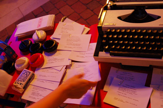
Type-written exericses. These would get stamped with a "Time for nothing" stamp upon completion. Time was measured with these timers, given out in stamped "Time for nothing" bags (visible in left corner).
Exercise 111: Wrap one thing. Unwrap another thing.
Exercsie 116: Turn your back to your partner. Walk away until you lose your reflection in their mirror.
Very surprised people at the market:
Grandma and grandson.
Exercise 103: Keep as many balloons in the air as possible. Use the fans to your advantage.
We were on the local news one night - around minute 11:30.
And here's a person who jumped on the truck and started reading the instructions to everyone nearby:
City Factory Invites you to Collaborate! from Kate Balug on Vimeo.
Final modules file and Rhino model.
A review of the project in 2+3D magazine that includes a video made by Bartek Gorka.
Thanks for an incredible semester to Anna, Neil, and everyone at Fab Academy!