Week 9
In this week's class we focused on input devices, which are components for interfacing embedded systems with the physical world. These could be buttons, motion detectors, temperature sensors, photoresistors or other sensors that can translate physical actions into digital signals.
Not to be confused with output devices like motors, displays, speakers, or LEDs, which we will see soon ;)* Spoiler: next week .
Types of Sensors
- Analog Sensors: Produce a continuous signal proportional to the measured parameter.
e.g.:
Phototransistors - Detect light intensity.
Load Cells - Measure weight or force.
Temperature Sensors - Such as thermistors, which detect temperature changes.
- Digital Sensors: Provide discrete signals, often in binary form.
e.g.:
Keypads - Detect specific key presses.
Touch Sensors - Identify touch or proximity.
Infrared Sensors - Detect obstacles or motion.
When selecting a sensor for a project, several factors must be considered. These include range and sensitivity, which determine the span of measurement and the smallest detectable change, as well as accuracy and precision, which refer to how close measurements are to the actual value and their consistency. Response time is another important characteristic, as it defines how quickly the sensor reacts to changes.
we discussed interfacing requirements, which depend on whether the sensor outputs analog or digital signals and whether additional components like amplifiers or signal conditioners are needed.
Interfacing sensors with microcontrollers requires understanding how they transmit data. Analog sensors connect to analog-to-digital converter (ADC) pins, which allow microcontrollers to read varying voltage levels. For instance, a phototransistor can be connected to an ADC pin to measure light intensity. Digital sensors, on the other hand, connect to digital input pins and often use communication protocols such as I²C, SPI, or UART. A keypad, for example, can be connected to digital inputs to detect key presses and respond accordingly.
Interfacing Sensors with Microcontrollers
Interfacing requirements depend on whether the sensor outputs analog or digital signals and whether additional components like amplifiers or signal conditioners are needed.
Analog sensors connect to analog-to-digital converter (ADC) pins, which allow microcontrollers to read varying voltage levels. For instance, a phototransistor can be connected to an ADC pin to measure light intensity.
Digital sensors, on the other hand, connect to digital input pins and often use communication protocols such as I²C, SPI, or UART. A keypad, for example, can be connected to digital inputs to detect key presses and respond accordingly.
Trying Out Sensors at the Lab
Hands on! So we tried using a variable resistors which are electronic components that allow you to adjust the resistance in a circuit, manually or automatically. Unlike fixed resistors, which have a constant resistance value, variable resistors can change their resistance to control voltage, current, or signal levels in an electrical circuit.
We chose a potenciometer and made a little circuit to give us a voltage reading.

void setup() {
  // put your setup code here, to run once:
  pinMode(17, INPUT);
  Serial.begin(115200);
}

void loop() {
  // put your main code here, to run repeatedly:
  int lecture = analogRead(17);
  Serial.println(lecture);
  delay(50);
}

Playing around with the potentiometer and turning the knob gives us a variable volage input. 4095V associated with the 3.3V output from our barduino board.
Then we tried a KY035 Hall Magnetic sensor (also called Hall effect) to see how it is affected by a metal bolt.
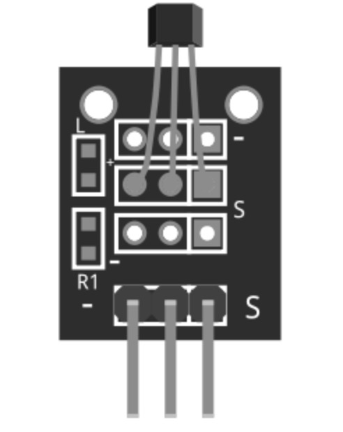
We coded this to observe the variable voltage response as we moved it closer and further away from the sensor.
int sensorPin = 17;   // interface pin with magnetic sensor
int val;              // variable to store read values

void setup() {
  pinMode(17, INPUT);   // set analog pin as input
  Serial.begin(115200);   // initialize serial interface
}

void loop() {
  val = analogRead(sensorPin);  // read sensor value
  Serial.println(val);          // print value to serial

  delay(100);
}
We tried yet another more sensor, this time the KY027, also known as the Magic Light Cup Effect.
By using PWN* Pulse Width Modulation to control the LEDs on each module, we can create the illusion of light being "magically" transferred from one module to another when tilted—similar to pouring water between two cups, which inspired the name.
In the Arduino sketch, we used both modules to achieve this effect. Each module contains a mercury switch, which provides a digital signal used to regulate LED brightness via PWM.
int ledPinA = 15;
int switchPinA = 13;
int switchStateA = 0;
int ledPinB = 8;
int switchPinB = 10;
int switchStateB = 0;
int brightness   = 0;

void setup()
{
pinMode(ledPinA, OUTPUT);
pinMode(ledPinB, OUTPUT);

pinMode(switchPinA, INPUT);
pinMode(switchPinB, INPUT);
}

void loop()
{
switchStateA = digitalRead(switchPinA);
if (switchStateA == HIGH && brightness != 255)
{
brightness ++;
}
switchStateB = digitalRead(switchPinB);
if (switchStateB == HIGH && brightness != 0)
{
brightness --;
}
analogWrite(ledPinA, brightness);  //  A slow fade out
analogWrite(ledPinB, 255 - brightness);  // B slow bright up
delay(20);
}
We connected two KY027 modules to our Barduino on separate sides of a breadboard and adjusted the code to match our pin configuration.

To set up the effect, we pllace the modules so that their mercury switches face opposite directions. As you tilt them, the brightness of one module’s LED decreases while the other increases, giving the illusion that light is flowing between them.
Fun!
Remember last week's board? We are using it again to include a button as an input.
I wanted to share a helpful technique our local instructor recommended. It involves taping all the required components onto a sheet of paper and bringing that to the soldering station. This way, you can clearly see each component on the left, along with its name and quantity next to it. I find it incredibly practical. Plus, the sheet provides space for useful notes or annotations or important drawings.

This is how it came out after soldering.

The switch I chose has a momentary action ( SPST* Single Pole Single Throw , normally open), operates wsith a maximum voltage of 12V DC, and supports a current of up to 50mA.
To program the board I need to get a hold a UPDI. Since I'm using the Attiny 412, I'll be using the toolchain described in Week 4.
These are how my connections look like.

It was in this moment that I had many mistakes. Some traces were too close together and ended up merging. I had accidentally placed a mounting hole over a connection, and more critically, I got the battery polarization wrong. Also the footprint for the coin battery holder didn’t account for the battery’s actual shape, only for the necessary connections. As a result, the unused parts of the footprint ended up touching the surface of the battery, unintentionally carrying voltage to other areas of the board.
And so I tried again.
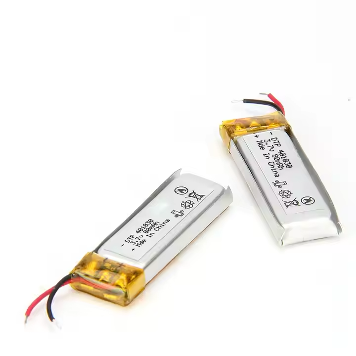
This time I replaced the button batteries with two 3.7V lithium batteries rechargable through an Adafruit Universal USB/DC/Solar Lithium/Ion/Polymer charger (bq24074).
I removed the button swith for a hall-effect omnipolar switch that would act as a toggle.
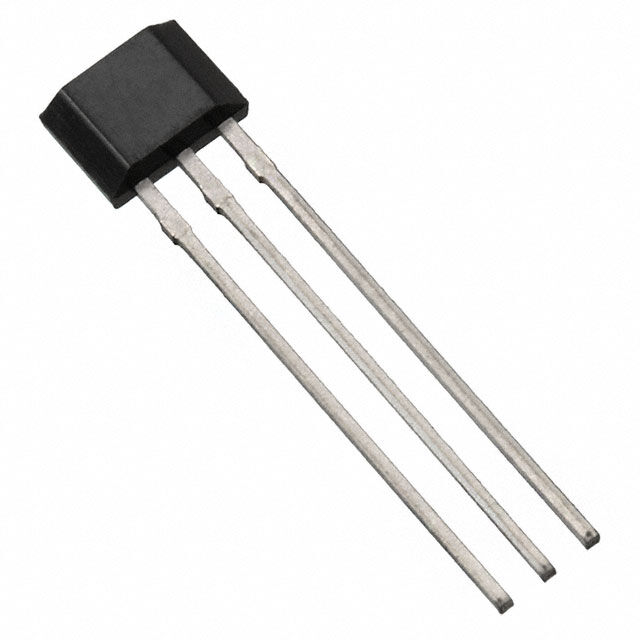
A toggle is another type of switch or control that alternates between two states, like on/off or enabled/disabled, each time it is activated.
I plugged the UPDI programmer and uploaded this code:
const int hallPin = 4;   // Hall sensor connected to PA3
const int ledPin1 = 2;
const int ledPin2 = 1;
const int ledPin3 = 0;
const int ledPin4 = 3;
   // Built-in LED pin
bool ledState = false;   // Keep track of LED state
bool lastHallState = HIGH; // Previous reading from Hall sensor

void setup() {
  //Serial.begin(9600);                     // Start serial communication
  pinMode(hallPin, INPUT_PULLUP);        // Use internal pull-up for Hall sensor
  pinMode(ledPin1, OUTPUT);               // Set LED pin as output
  digitalWrite(ledPin1, LOW);
   pinMode(ledPin2, OUTPUT);               // Set LED pin as output
  digitalWrite(ledPin2, LOW);
   pinMode(ledPin3, OUTPUT);               // Set LED pin as output
  digitalWrite(ledPin3, LOW);
   pinMode(ledPin4, OUTPUT);               // Set LED pin as output
  digitalWrite(ledPin4, LOW);          // Start with LED off
  //Serial.println("Ready! Bring magnet close to toggle LED.");
}

void loop() {
  int hallStatus = digitalRead(hallPin);  // Read Hall sensor

  // Detect falling edge: HIGH → LOW (magnet just got close)
  if (lastHallState == HIGH && hallStatus == LOW) {
    ledState = !ledState;                         // Toggle the LED state
    digitalWrite(ledPin1, ledState ? HIGH : LOW);
     digitalWrite(ledPin2, ledState ? HIGH : LOW);
      digitalWrite(ledPin3, ledState ? HIGH : LOW);
       digitalWrite(ledPin4, ledState ? HIGH : LOW); // Update the LED
   // Serial.print("Magnet Detected! LED ");
    //Serial.println(ledState ? "ON" : "OFF");
  }

  lastHallState = hallStatus;  // Update the previous Hall sensor state
  delay(50);                   // Debounce delay
}
! Note: The megaTinyCore board manager rewires the pins differently from their default hardware, so you might encounter some problems while programming it. Double check your connections with this simple code will be of help you trace down the new pin number assigned.
I programmed the board to read the state of the Hall effect sensor on pin 4 to detect a magnet, and connected four LEDs to pins 0, 1, 2, and 3.
In the setup() function, I configured the Hall sensor as an input with an internal pull-up resistor, and set all the LED pins as outputs, starting with them turned off.
In the loop(), I constantly read the Hall sensor. When I detect a falling edge -meaning the sensor goes from HIGH to LOW (indicating a magnet just got close)—I toggle a boolean variable ledState. Depending on that variable, I turn all four LEDs either on or off.
I also added a small delay to debounce the signal and avoid repeated toggles from a single magnet pass.
Initially I tried it in the breadboard with a cuttout Attiny412 board* more on this during week 11 I did and powered it through the UPDI.
You can see me bringing the magnet closer to the Hall effect to get led on.
And after trial and error this is how it turned out! .......... actually, maybe I'll leave you hanging and reveal it next week ;)
You can access the .ino file and the Kicad project.
Thanks for catching up. xoxoxo