intro
Goal of this week is to probe an input device(s)’s analogue levels and digital signals as group, document your work on the group work page and reflect on your individual page what you learned. As individual assignment the goal is to measure something: add a sensor to a microcontroller board that you have designed and read it.
For my final project I need user input (knobs, buttons), file input (sd card) and most importantly analogue control signals as input. (USB)midi input will be something to check in week 13 (communication, networking). Since I teach a course on sensors I like to focus on an unknown bit which I need for my final project: the analogue input stage!
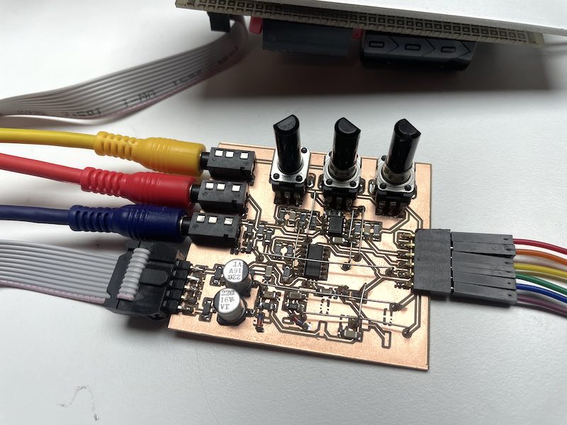
the finalised input stage under test
A generic synthesiser module uses three (analogue) signals, of which the pitch (cv) and trigger (gate) are the most essential. Basically the gate tells when to play a note, the pitch at which frequency. One (or more) modulation inputs are usually added for changing an essential parameters in the sound, for instance filtering (frequency), envelope characteristics, etc.
group work
During the group session @waag Erwin takes us through the basics.
- Digital vs. Analogue
- ADC resolution: 8 bit, 10 bit, 12 bit source
- reference voltage can be set internally or offered externally!
- low: [0..0.33VCC] - high [0.66VCC..VCC] (so, a gap mid way might be in there…)
- protocols:
- 1 wire - dallas temperature DS18D20 sensor (VCC, Data, GND (or VCC+Data combined)). A sensor has a hard-coded 2^64 bit identifier. Similar: DHT11 moisture/temp sensor
- I2C data+clock 7bit address. 400kHz standard. (PCA9555 IO expander, BME280 temp/hum, VL51L0X laser)
- SPI (MOSI and MISO are renamed COPI and CIPO (controller and periferal)), SCK (clock) and CS (previously SS) (DS1302, SD cards, BME280 temp/hum). Very fast, more wires (MHz)
- Serial (UART, TTL serial) (US-100 ultrasonic sensor, NEO-8M GPS, MH-Z19B CO2, SI-3BM geiger)
- PWM (duty cycle) for use in EMC-noisy environment (IR, PPM communication)
- protocols can be emulated in software (bit banging) or with dedicated hardware (USART)
- measurements in SI units (s, m, kg, A, K, mol, cd)
- volt = kg * m^2 * s^-3 * A^-1
- volt = watt / amp (P=V*I)
- watt = joule / sec
- joule = newton * meter
- newton = kg * m / sec / sec (i.e. gravity = 9.8 m/s^2)
DHT11 moisture and temperature sensor
So, as example sensor we choose the DHT11 for Joe’s mushroom sensor. [https://github.com/adafruit/DHT-sensor-library]. The DF-robot library for the DHT 11 seems to be working ok. Installed through Arduino’s library manager
/*!
 * @file readDHT11.ino
 * @brief DHT11 is used to read the temperature and humidity of the current environment.
 * @copyright   Copyright (c) 2010 DFRobot Co.Ltd (http://www.dfrobot.com)
 * @license     The MIT License (MIT)
 * @author [Wuxiao](xiao.wu@dfrobot.com)
 * @version  V1.0
 * @date  2018-09-14
 * @url https://github.com/DFRobot/DFRobot_DHT11
 */
#include <DFRobot_DHT11.h>
DFRobot_DHT11 DHT;
#define DHT11_PIN 7
void setup(){
  Serial.begin(115200);
  while(!Serial){}
    pinMode(6,OUTPUT);
    digitalWrite(6,HIGH);
    pinMode(5,OUTPUT);
}
void loop(){
  DHT.read(DHT11_PIN);
  Serial.print(DHT.temperature);
  Serial.print(',');
  Serial.println(DHT.humidity);
  delay(1000);
}
The sensor is relatively slow (1 sample per second) - the library spits out SI units (as in temperature in degrees, moisture as relative humidity in percentage)
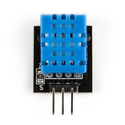
DHT11 sensor
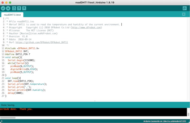
code example in Arduino
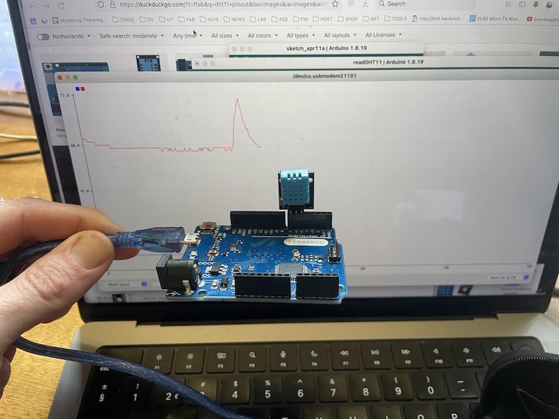
sensor connected to Arduino
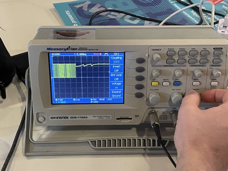
communication (digital serial data) on oscilloscope
The following data shows Waag’s environment (rainy day, not to hot). The spike in the middle is me breathing quickly on the sensor (and decay.. Basically a step response :)
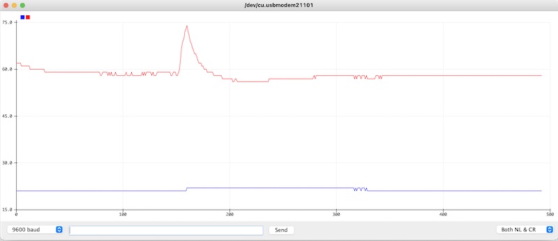
data of sensor, 22 degrees, 60% humidity
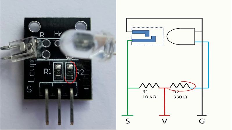
RGB LED as light sensor
Quick grab from the ‘37 sensor kit’. Can you use an RGB LED as colour sensor? The RGB led works quite ok as light sensor in forward-voltage mode (alternatively, reverse bias or ‘capacitive’ could have been used, but the small PCB it lives on allows only for forward voltage).
In the sketch the sensitivity is quite ok (tested with phone flashlight) but doing differential sensing (i.e. substracting the Green LED from the RED LED) shows a minor difference in sensitivity, but no difference using coloured light (using pieces of transparent acrylic). So. perhaps more research is needed, but so far no colour dependency…
// measuring forward voltage on an RGB-LED
// GND = A3
// R = A2
// G = A1
// B = A0
// averaging the values, plotting differences to see
// whether an RGB-LED is also colour-sensitive
#define SAMPLES 10
int buffer [SAMPLES];
void setup() {
  Serial.begin(115200);
  while(!Serial){;} // for leonardo, wait for connection
  pinMode(A3,OUTPUT); //GND for the RGB-LED
}
void loop() {
  static unsigned long looptime;
  static int n;
  if(millis()>looptime+49){
    looptime = millis();
      buffer[n] = analogRead(A1)-analogRead(A0);
      n++;
      if(n>SAMPLES-1) n = 0;
      // and now calculating the average
      int average = 0;
      for(int i=0; i<SAMPLES; i++){
        average += buffer[i];
      }
      Serial.println(average/SAMPLES);
  }
}
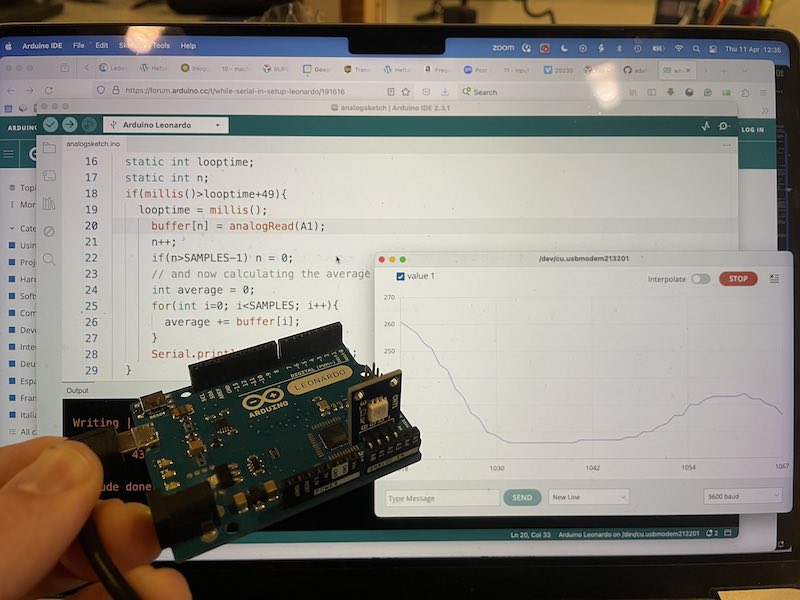
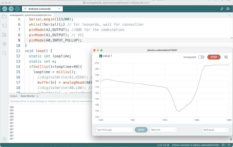
RGB LED as light sensor
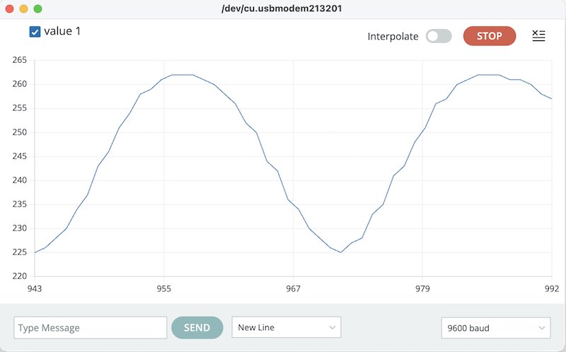
LED data (using a phone flash as light source)
At home I try to build a sketch which works as a reflective sensor: turn on the RED LED and sample the blue and green at the same time. It takes a while to get a sketch running (see below) but it only works when I agree that the common anode is in fact a common cathode (although it is marked with a (-) sign). Now I am confused. This requires more testing (but allas, supply side time management.. I have to continue with my final project)
KY-039 heart rate sensor
I was hoping to do synchronous detection, sadly the photodiode in the KY-039 sensor configuration is also using the VCC for pull-up, so switching the VCC for turning on and off the LED does not work. The KY-039 itself works ok-ish as heart-rate sensor, it requires careful bending and shifting the photodiode and LED to illuminate a tiny portion of (for example) your fingertip.
KY039 photodiode and IR LED
Quick Arduino sketch plotting 20 values/sec
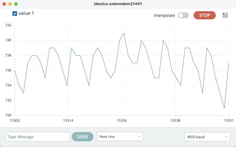
Heartrate measurement. 60 bpm. Pretty relaxed...
individual project
For this week I would like to explore all input circuitry for the Furby Synthesiser Module. This means the user input (SD card, encoder) and also signal input from the rest of the modular synthesizer. It should be possible to interface the module to other inputs (control inputs, sequencer, etc) but also use it as manual, stand-alone sound generater.
analogue input
The Pico has three ADC inputs, multiplexed internally (or check: 3 separate units? nah… ). The analogue refernce voltage can be set externally but is usually set at 3.3V. This means that the 12 bit ADC range of 3.3V has a resolution of 0.8 mV
Synthesiser modules typically have output voltages in the range of 0..10V. A typical range for CV is 1 V per octave. To have a span of 10 octaves you need 10V. Trigger and gate signals are usually different, and simply ‘digital’. This means that they switch between 10V (5V) and 0V for on- and off. A different system is Moog’s S-trigger which is an open-loop switch contact (and compeletely incompatible)
For the analogue inputs (CV and Modulation) I have the following requirements:
- protect the Pico’s input from voltages outside its working range: not lower than 0V and not higher than 3.3V
- adjust offset for the CV (which can also be used as input when no external CV signal is applied)
- adjust offset and gain for Modulation (which can also be used as input when no external signal is applied)
For the gate / trigger I have the following requiremnts:
- modes: one-shot (trigger), gated (play while on), looping (on/off). These modes can be set with the menu/display
- external input, switch?
For the gate/trigger I might use a switch with two normal positions and one spring-return for manual gate.
A quick search online results in simple protection and filtering circuits like the following:
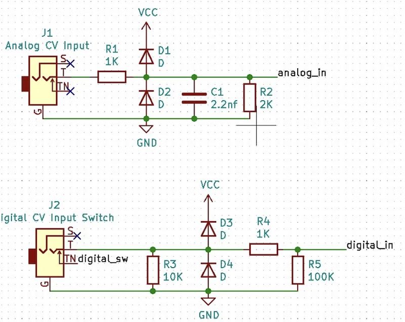
Simple input protection
This shows at least the basics: two diodes (zener diodes) to keep input voltages in the 0..3.3V range. The resistors and capacitor act as a low-pass filter and voltage divider, in the case of 1k-2k limiting a 5V signal to 3.3V.
Although this might work, for my project this won’t suffice. In the same tread a nice series of designs by Mutable Instruments is discussed. Although the company is not longer producing their designs, the design sources are a wealth of inspiration for modular builders. Their designs started out as very fabbable, squeezing out every bit of sound possible from AVR’s, typically augmented by dedicated filter (VCF/VCA) designs.
Taking one example synth module (the braids run by a 3.3V (STM) microcontoller), here is the full schematic, the following two input circuits might be useful:
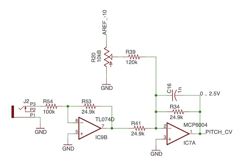
Input circuit for CV, potentiometer to control offset
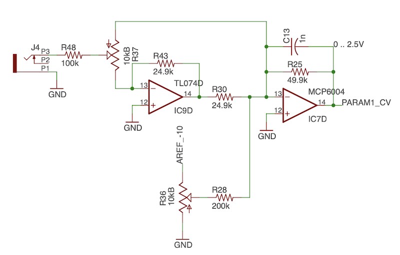
input circuit for mod, potentiometers to controll ofsset and gain
The gate has (simply) to accept a wide input and trigger clearly and digitally. A transistor suffices for this. Note that for the reference voltage, a voltage of -10V is chosen. Reason is that the amplifiers used are set in an inverting configuration. The output of each stage is in 0V..2.5V range, so the reference voltage for analogue input is set at 2.5V using a precision zener diode.
For the CV input the high-voltage opamp reduces the input by a factor 4 (100k/25k). The low-voltage opamp is used as summation amplifier (inverting), summing the previous opamp and the potentiometer offset. The gain is set at 1 (25k-25k) so by adding (inverted) a fraction of -10V you can set an offset of 0..10V for the entire range. For the modulation circuit the same setup is used, but now also an input poteniometer is used to set the initial gain (0..1) of the modulation signal.
The benefit of this circuit is that both the offset potentiometers can be used to control the synth when no external input is present. Eventually the CV input will be used for the playback frequency, the trigger for the looping. The modulation can be used (for example, this is something that has to be experimented with) to set the ‘grain’ or sample length, or the sample starting point.
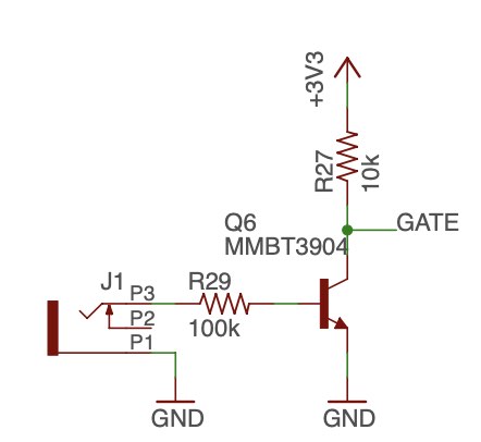
gate circuit
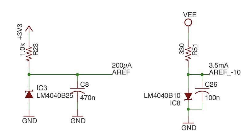
refernce voltages: -10V and 2.5V
The used componets such as the MCP6004 might be very suitable for a fabable design. The TL072 used in the design is powered by the +/- 12V of the synth (so any input between -12 and +12V is acceptable). The MCP6002 is powered by 3.3V and keeps the signals within acceptable range for a 3.3V microcontroller. Hence the design is not using the input-protection diodes as seen in the first circuit. The TL072 and MCP6002 are not part of the fablab inventory so we have to start component hunting….
fabrication
In KiCAD I design a schematic based on the Mutable Instruments version. Since I mostly have DIP components around, It is quite a struggle to find suitable SMD components. Eventually I settle for a TLC272 as low voltage opamp and an LM324 as the high-voltage side. for the Zener diodes (2.5V and 10V) I have to wait a bit (ordered a component set at Amazon). Transistors are a tricky bunch, especially in SOT23 packaging. Finding some old ones and searching the markings online results in weird and exotic datasheets. The ones I have (with a 2G marking) - I assume them to be BC850 NPN general purpose…..
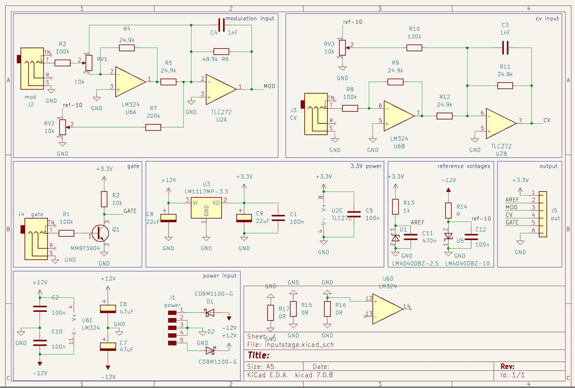
Schematic for inputstage
Below the kicad design files:
Single-layer design of this circuit is quite a hassle. I chose to route most of the tracks on a single side and add a couple (9 in total) bridging tracks on the other side.
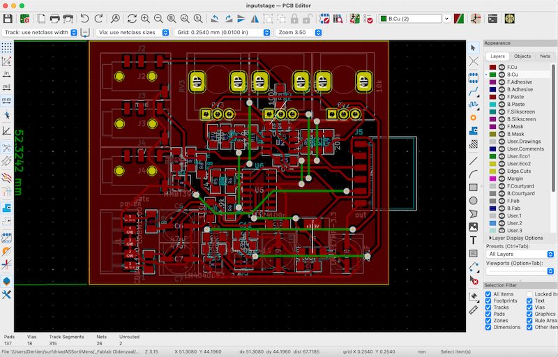
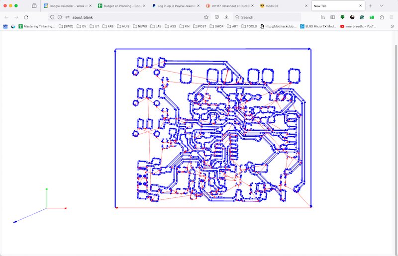
PCB design in Kicad using 9(!) bridges
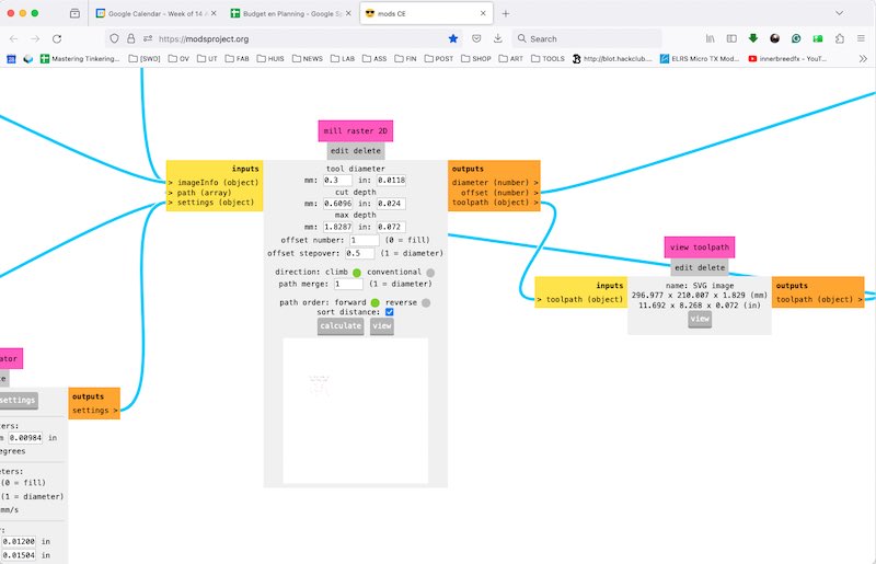
I process the SVG files generated by KiCAD. For the drill layer I have to edit the F-Cu layer to remove all traces and just leave the holes. It is not possible (or I cannot find) how to make mods do a hole with a single plunge instead of making a small rotation. I use the following settings in mods:
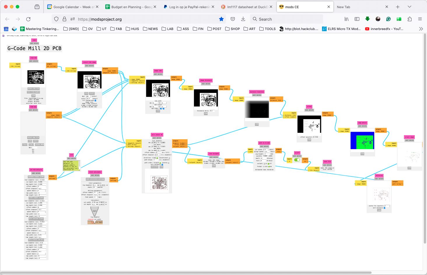
PCB track drawing processing in mods
drill settings in mods
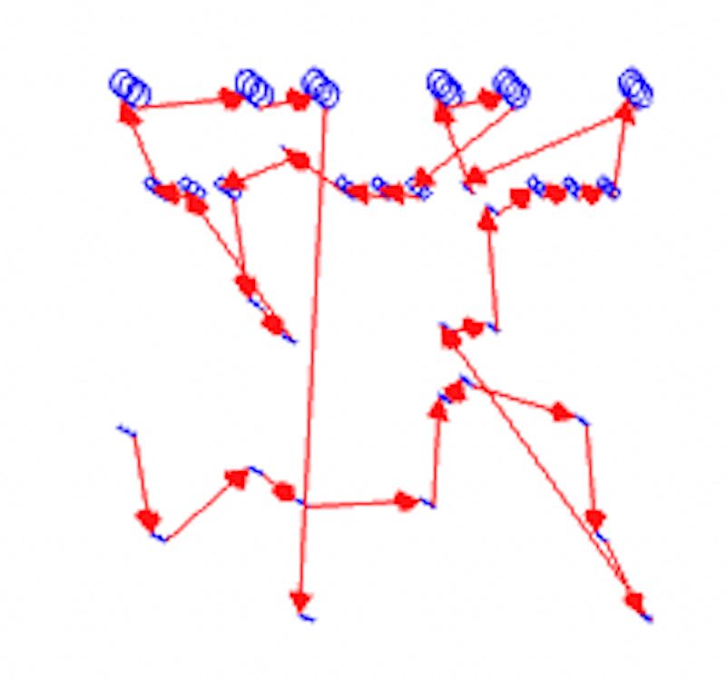
resulting in the following gcode (visualisation)
gcode visualisation for tracks
gcode visualisation for holes
I mill the board, however the drill-file generated with Inkscape comes with an orientation shift and causes the machine to reach an end-stop before I can pause. Since now the origin is lost I chose not to try again with the drill file but to do manual drilling.
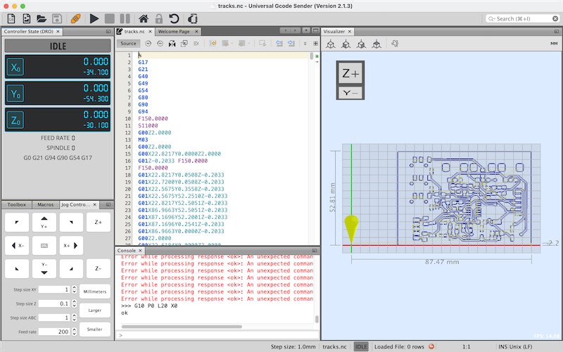
ugs ready to start milling the tracks
Again, I use a 15deg v-bit, results are quite ok. Next time I need to reduce the milling depth a bit further.
milling the input board
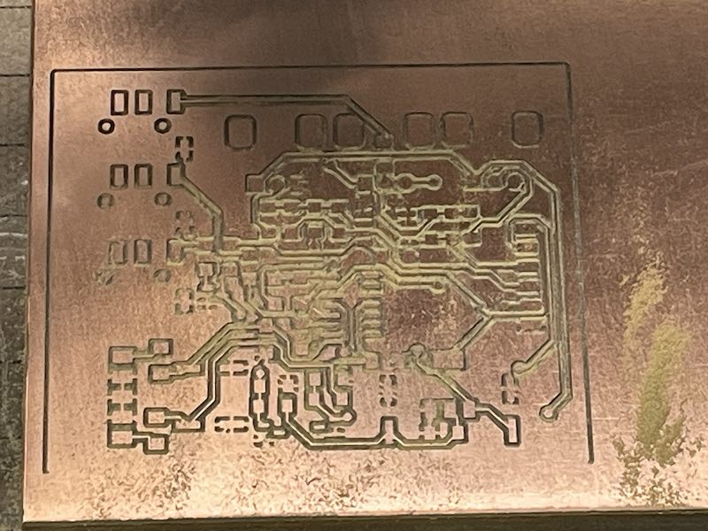
input board ready
The via’s appear to be to small for hand-drilling so I use wire bridges on the top-side of the board instead. Overall the tracks are thin and fragile. Soldering the 1206 components and the SO8 and SO14 works ok. Potentiometers and jack sockets need a bit of work to fit as SMD components.
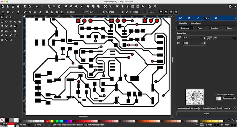
Editing F-Cu layer in inkscape to generate an SVG drill file
Eventually this did result in a millable gcode file, however, a zero-position error made the machine go out of bounds and hit the end-stop. (Next time: check your files, make sure they all have the same origin, check again and then check again… )
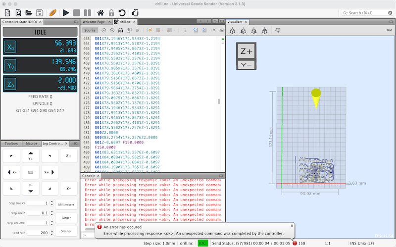
Milling machine hitting an endstop
I need to mount 9 ‘bridges’ on the top side of the board. Not ideal and adding to the fagility. Overall very time consuming process
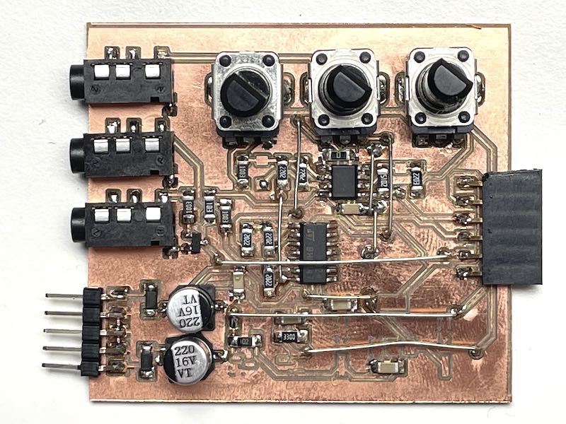
completed input board
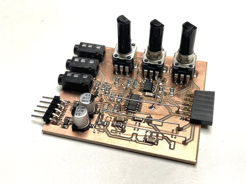
completed input board, 9 bridges...
testing
After a basic conductivity test I first connect 3.3V from a Pico to the board. Since I don’t have the LM1117 3.3V regulator in place, the Pico has to supply 3.3V for the low voltage opamps. With this I test the gate circuit and the 2.5V reference. Since I used a 2.7V zener I expect more than 2.5 V
inputboard under test
Next up I connect a -12..12V supply (synth module I made earlier using a 15V AC supply, a half-bridge rectifier, capacitors and 78L12 79L12 pair) Also the -10V is working and output signals seem within bounds/ The circuit works: The negative supply: -10.18V (zener diode) and AREF equals 2.60V (zener diode reference)
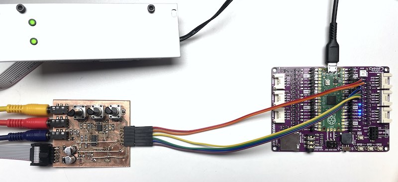
input board connected to Pico
Next up I use a simple sketch in the pico to plot analogue values. I use a pico on the cytron maker pi board because it has easy (male) breakout pins that I can hook up to my board.
void setup() {
  // put your setup code here, to run once:
Serial.begin(115200);
while(!Serial);
Serial.println("modulation,cv,gate");
}

void loop() {
  // put your main code here, to run repeatedly:
  Serial.print(analogRead(A0));
  Serial.print(',');
  Serial.print(analogRead(A1));
  Serial.print(',');
  Serial.println(analogRead(A2));
  delay(50);
}
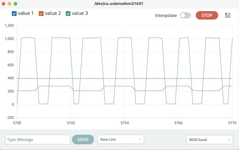
Gate and CV signal
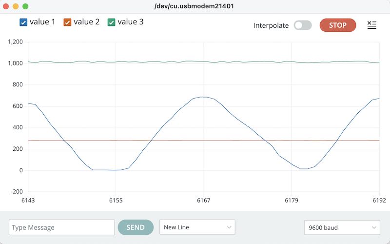
Modulation input
I connect a Arturia Keystep controller (which has a gate, pitch and modulation output) and connect first the gate. When this is working I connect first the CV and finally the modulation signal. Everything seems to be working fine, see the following video. Only potentiometers 1 and 3 work in reverse (so the CV bias and modulation gain). modulation offset (P2) works fine (clockwise). Since this is an analogue signal path, it is not easy to change in software so attention has to be paid to this in the final version.
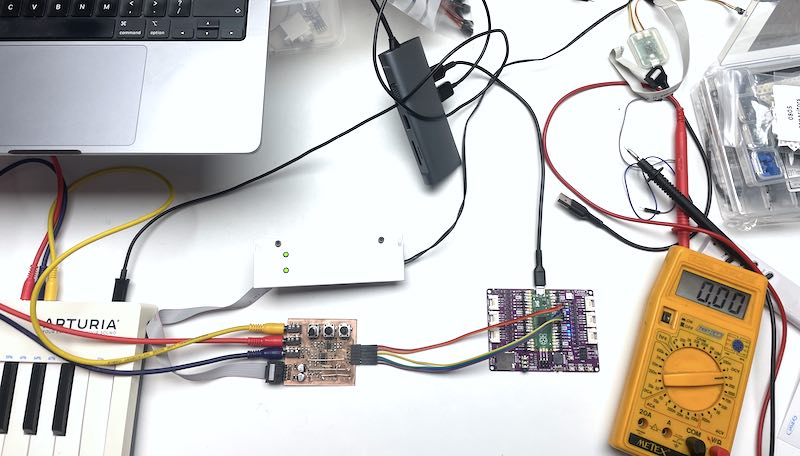
Connecting modular supply, keystep and pico
In the following video you can see the gate signal (green) when I press a key, the cv signal (red) which changes with the notes I play (an octave apart) and finally the modulation signal (blue) which is caused by operating a slider on the arturia board.
gate, cv and modulation input registered by the Pico
encoder
The incremental encoder is switch-based. It contains two switches which make contact or break contact based on the angular position. The two switches are spaced 90deg in phase so the rotation direction can be determined (even in quadrature for more resolution). There are two main ways of interfacing: one is polling, the other is using external interrupt. For polling the main loop can be used (when run at a high frequency) or a (dedicated) timer interrupt.
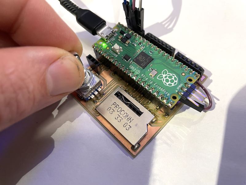
Encoder on the week08 board
timer interrupt
The first example is one using timer interrupt (so a timer does the polling), but now adapted for pico using the following timer interrupt library. The code uses an interrupt at 1 kHz on a ‘pseudo’ timer which internally uses the hardware timer interrupts Pico can provide. The code uses two channels and decodes the output in quadrature. This means that per click of the encoder (switch) you get a 4-step position increment or decrement. You can actually see the intermediate steps too, however the mechanical ‘click’ forces te position to a 4-step increment.
// encoder example using RPI PICO TimerInterrupt library
#include "RPi_Pico_TimerInterrupt.h"
int phaseA = 8;
int phaseB = 7;
volatile long position = 0;
bool encoderhandler(struct repeating_timer *t) {
  (void)t;
  static int dA = 0;
  static int dB = 0;
  int A = digitalRead(phaseA);
  int B = digitalRead(phaseB);
  // full quadrature:
  if ((A == 1 && dA == 0 && B == 0) || (A == 0 && dA == 1 && B == 1) || (B == 1 && dB == 0 && A == 1) || (B == 0 && dB == 1 && A == 0)) position++;
  if ((B == 1 && dB == 0 && A == 0) || (B == 0 && dB == 1 && A == 1) || (A == 1 && dA == 0 && B == 1) || (A == 0 && dA == 1 && B == 0)) position--;
  dA = A;  // store previous values
  dB = B;  // store previous values
  return true;
}
// Init RPI_PICO_Timer, can use any from 0-15 pseudo-hardware timers
RPI_PICO_Timer ITimer0(0);
void setup() {
  Serial.begin(115200);
  while (!Serial); // wait for usb terminal connection
  pinMode(phaseA, INPUT_PULLUP);
  pinMode(phaseB, INPUT_PULLUP);
  ITimer0.attachInterruptInterval(1 * 1000, encoderhandler);
}
void loop() {
  Serial.println(position); // volatile
  delay(100);
}
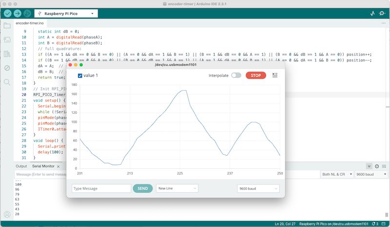
Encoder interface using timer interrupt
The response is smooth. Using the timerinterval the processor load can be tuned. The response is in full quadrature.
external interrupt
It is also possible to use external interrupts to do the counting. As described for example in this arduino forum post it is quite straightforward to assign an interrupt function to a pin change. For fast optical incremental encoders I often use a similar way (again, I had not tried this with Pico before, only with Atmel and Arduino derivatives) Although the code is very compact, the switch based encoder knob suffers too much from contact bounce so the outcome is very unreliable
// encoder example using external interrupt
int phaseA = 7;
int phaseB = 8;
volatile long position = 0;
void setup() {
  Serial.begin(115200);
  while (!Serial); // wait for usb terminal connection
  pinMode(phaseA, INPUT_PULLUP);
  pinMode(phaseB, INPUT_PULLUP);
  attachInterrupt(phaseA, encoderhandler, RISING); // using one encoder, not quadrature for now
}
void loop() {
  Serial.println(position); // volatile
  delay(100);
}
void encoderhandler(){
  if(digitalRead(phaseB)>0) position++; else position--;
}
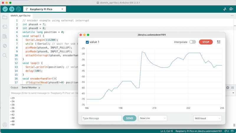
Encoder signal using external interrupt
As can be seen with the steep jumps and kinks in the signal, due to contact bounce the signal is quite unreliable. It might work as user input, but probably very frustratingly.
but wait, PIO!
The previous two are ones I quite regularly use with Atmel / Arduino derivatives. The Pico however offers an aditional option by using PIO, as explained in these sources. In order to quickly test the sources in a uniform way I rewrite the example to work with Arduino:
// Encoder on Pico using PIO example from https://github.com/jamon/pi-pico-pio-quadrature-encoder/
#include <hardware/pio.h>
#include "quadrature.pio.h"
#define QUADRATURE_A_PIN 7
#define QUADRATURE_B_PIN 8
PIO pio = pio0;
unsigned int sm = pio_claim_unused_sm(pio, true);
void setup() {
  Serial.begin(115200);
  while (!Serial);
  pinMode(QUADRATURE_A_PIN,INPUT_PULLUP);
  pinMode(QUADRATURE_B_PIN,INPUT_PULLUP);
  unsigned int offset = pio_add_program(pio, &quadratureA_program);
  quadratureA_program_init(pio, sm, offset, QUADRATURE_A_PIN, QUADRATURE_B_PIN);
}
void loop() {
  delay(100);
  pio_sm_exec_wait_blocking(pio, sm, pio_encode_in(pio_x, 32));
  int x = pio_sm_get_blocking(pio, sm);
  Serial.println(x);
}
Again, the code works nicely. The pio assembly code is given in the accompanying assembly file, which is made accessible through a cpp header file. The assembly code for a single encoder unit is the following:
.program quadratureA
start:
    wait 1 pin 0            ; wait for A == 1
    jmp PIN, wait_high      ; if B == 0
    mov y, !x                   ; x++ {
    jmp y--, nop1               ;
nop1:                           ;
    mov x, !y                   ; }
    jmp nop2
wait_high:
    jmp x--, nop2           ; x-- {
nop2:                       ; }

    wait 0 PIN 0            ; wait for A == 0
    jmp PIN, wait_low       ; if B == 0
    jmp x--, start               ; x-- {
                               ; }
wait_low:                   ; else
    mov y, !x                   ; x++ {
    jmp y--, nop4               ;
nop4:                           ;
    mov x, !y                   ;
    jmp start                   ; }
which is exactly what the external interrupt example described earlier did. Now the question is why the PIO examble behaves better in terms of switching noise / debouncing than the first Arduino example. For now no answer, but it might need more testing. Next up I also have to set up the VScode environment to compile pio code properly.
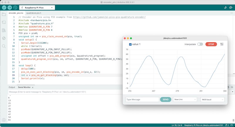
encoder implementation using pio
Overall I think the timer interrupt suffers the least from contact bounce, so it might be best to test whether it has an impact on the playback routine. Next up the PIO solution might be the best choice.
SD card
Just as a quick test (since it concerns input) - the standard example for SD card access works using the following pin definitions at the top using the standard cardinfo.ino example:
const int _MISO = 12;
const int _MOSI = 11;
const int _CS = 15;
const int _SCK = 10;
In the example code it redirects the Pico automatically towards the second SPI unit. This is not done in all examples, so I’m happy that I found the most elaborate (working) one (cardinfo.ino).
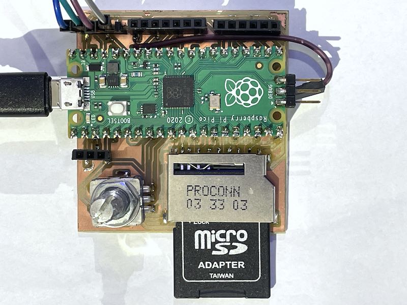
8GB sd card in converter
Note that at first, using a 64GB SDHC card the program throws a ‘card not detected’ error. A more modest 8GB SDHC FAT32 formatted card does however work. For the final design this is something to take into account. Also as socket I used a large size SD card (since that one was available). For the final design I’ll make sure to use a microSD socket that actually can be soldered by hand (the microSD sockets at hand had all the pins under the casing, so inaccessible..)
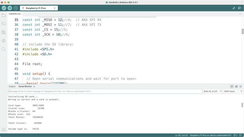
SD card source in arduino
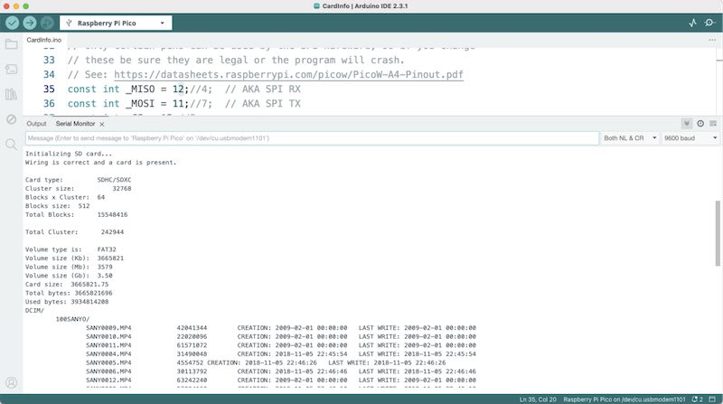
cardinfo.ino program in action
learning outcomes
Demonstrate workflows used in sensing something with input device(s) and MCU board. In this case, besides testing sensors on the board I earlier made, I developed an analog input stage which I will need for my final assignment. (And it seems to be working fine, yay!)
evaluation checklist
- Linked to the group assignment page.
- Documented what you learned from interfacing an input device(s) to your microcontroller and optionally, how the physical property relates to the measured results.
- Documented your design and fabrication process or linked to the board you made in a previous assignment.
- Explained the programming process(es) you used.
- Explained any problems you encountered and how you fixed them.
- Included original design files and source code.
- Included a ‘hero shot’ of your board.
lessons learned, tips and tricks
(or, the most insightful mistakes I made) The board worked at first go (but notice, I DID check for shorts, conductivity, supply voltages, orientation etc. before applying the +/- 12V supply) However,
- the resulting board is fragile and not easy to debug (which is its primary purpose)
- the resulting board is not immediately useful in the final design as such
- the components cannot be recycled when the board has served its purpose
So. Although I admire the machine, workflow and possibilities, for this specific purpose it might not have been the best choice for testing the input stage design. For the next time (since I did do things in a way that can definitely be improved) I plan to
- work with larger, much larger, vias
- check milling depth (it might be I milled deeper than necessary)
- find a better way to make drill files - perhaps using the bottom layer as starting point
- check orientation and origin in the files. Make sure the datum (origin) is placed at a sensible place in KiCAD
- Use FR4 with proper vacuum cleaner / dust extraction? Research into health issues. The FR1 is sooo fragile..
Another not-earlier-encountered thing is the (lack of) workflow for processing a drill file from KiCAD through mods. I ended up editing a drl file saved as svg in inkscape first (but this contains crosses where drill-holes should be) and I ended up eventually editing just a top-layer SVG drawing (with holes marked in the output settings pane), colouring the holes and removing all other artefacts.
left for todo
- Many, many great modular synth resources out there. List to check
- diving into pico PIO assembly (and set up the debugger properly) - see this link
- get the RGB LED working as colour sensor. Again (still) with minimal (or no) additional parts.. it -should- be possible…
reflection
Overall the manufacturing process of the input stage was very time-consuming and I wonder how much time is saved with respect to using a breadboard. It -did- work at first go, so working carefully and methodically paid off. Usually I end up with errors that I need to fix. I think I made most of the errors possible for this circuit in a previous life. The errors I didn’t make (because I already made them at another time) were:
- swapping the polarity of the power cable. It is -12 GND GND GND +12. You would assume starting with the positive voltage on pin 1 is the thing. It isn’t
- swapping the power leads on the LM324. It has the ground (or VEE, low voltage) on the TOP side (so pin 11) and the VCC on pin 4
- reversing zener diodes, especially when working with a negative supply
- forgetting to check the pinout of the used 3.5mm jack socket (and checking footprint with available component)
- forgetting to check the pinout of a used SOT23 transistor
- trying to drill 0.4mm holes with a hand drill (or small dremel drill press)
- designing a board before all the parts have arrived (without tolerant footprints)
I also like (to think) that I’m actually arriving at a level where I understand most analogue circuits (at least not too complicated ones dealing with opamps) and understand the methodical approach, also in selecting the circuits out there that -might- work, and the ones that could do a better job instead.
I also like (to think) that in the Pico ecosystem I am getting to the point where I know now how to do most things I regularly do on any other Arduino board, but can take advantage of the benefits (faster processor, flexible hardware, more memory, PIO)
copyrights and references
- for the input circuits I made use of (and reproduced bits) of the braids design by Mutable Instruments