group assignment:
characterize the design rules for your in-house PCB production process
extra credit: send a PCB out to a board house
individual assignment:
make and test the development board that you designed
to interact and communicate with an embedded microcontroller
extra credit: make it with another process
GROUP ASSIGNMENT
The group work can be found here.
INDIVIDUAL ASSIGNMENT:
I started by studying the type of controller i was going to use.
with the class' convenience we chose to go with the CH340 for the microcontroller.
From alldatasheet the reference will be like:
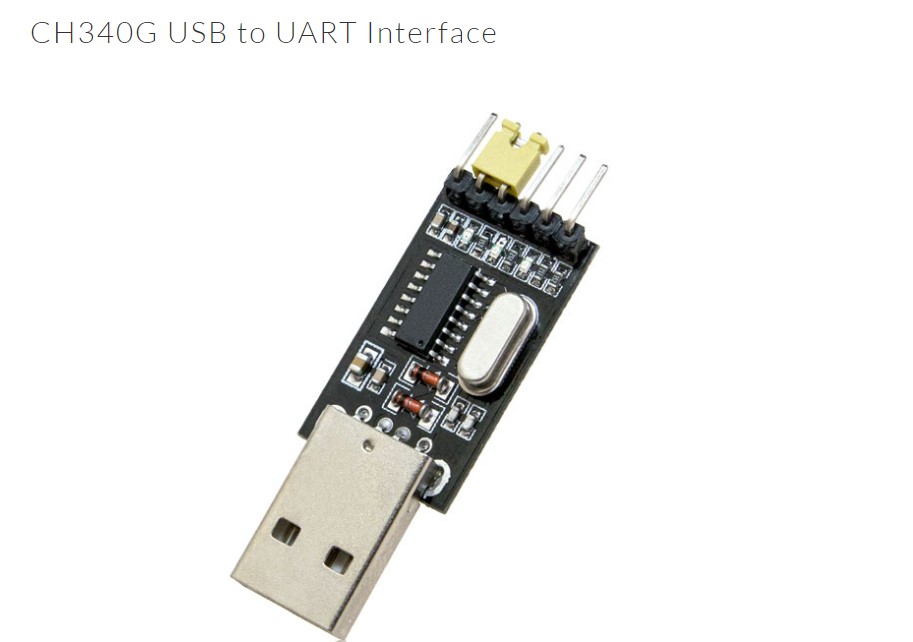 the whole data sheet can be found here
However the other interesting thing that i found about this device is:
The pin out diagram:
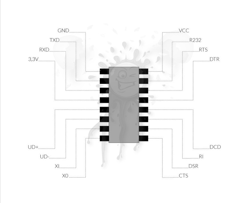 There are other steps to make:
* Choose Communication protocol
* List components required
* Design the schematic
* Create a PCB layout
* Generate the Gerber files/ g code
* Mill and cut the PCB
* Sloder components on
* Connect the USB in the computer and update the drivers
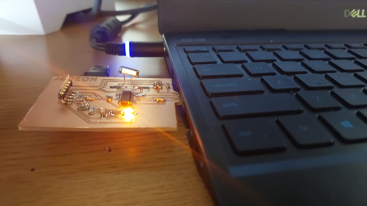
* Test on a computer and send a code to turn on the light
Choose Communication protocol:* UART
Why? Because bsed on this website the application of CH340 is to do USB UART conversion.
 we are using the CH340 G as an advanced version of the series.
* List components required
The circuit we are using will comprise following components:
- CH340G
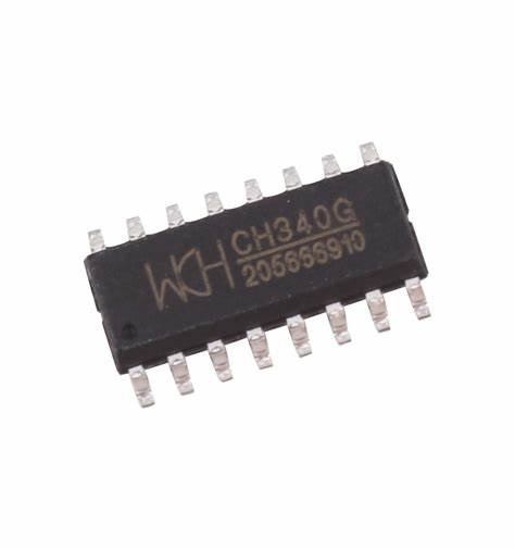
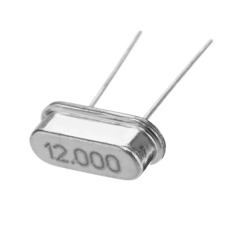
- 12 MHz Crystal Oscillator
- 1K resistors
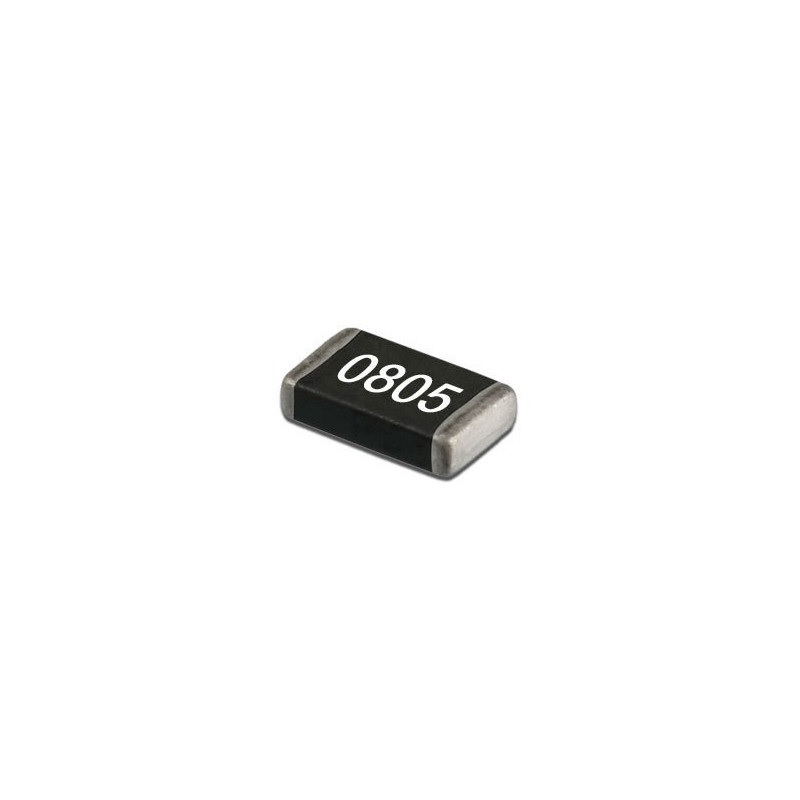
- 100nf capacitors
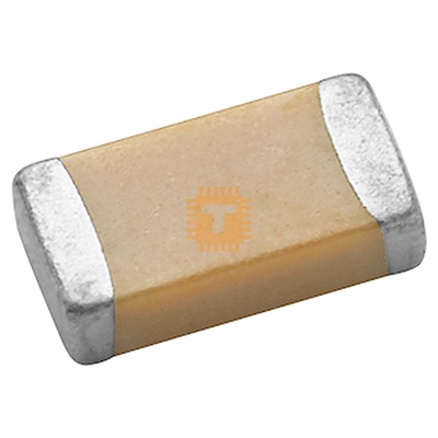
- 0805 package LED

- One layer PCB copper board

* Design the schematic
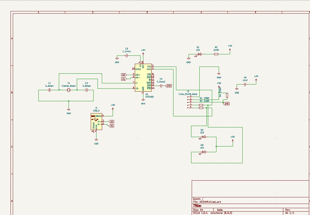
The KiCAD software helped me design the schematic diagram which i converted into the board.
After connecting all components. I had to check for errors.
Few warnings were mentioned but cleared them.
 * Create a PCB layout
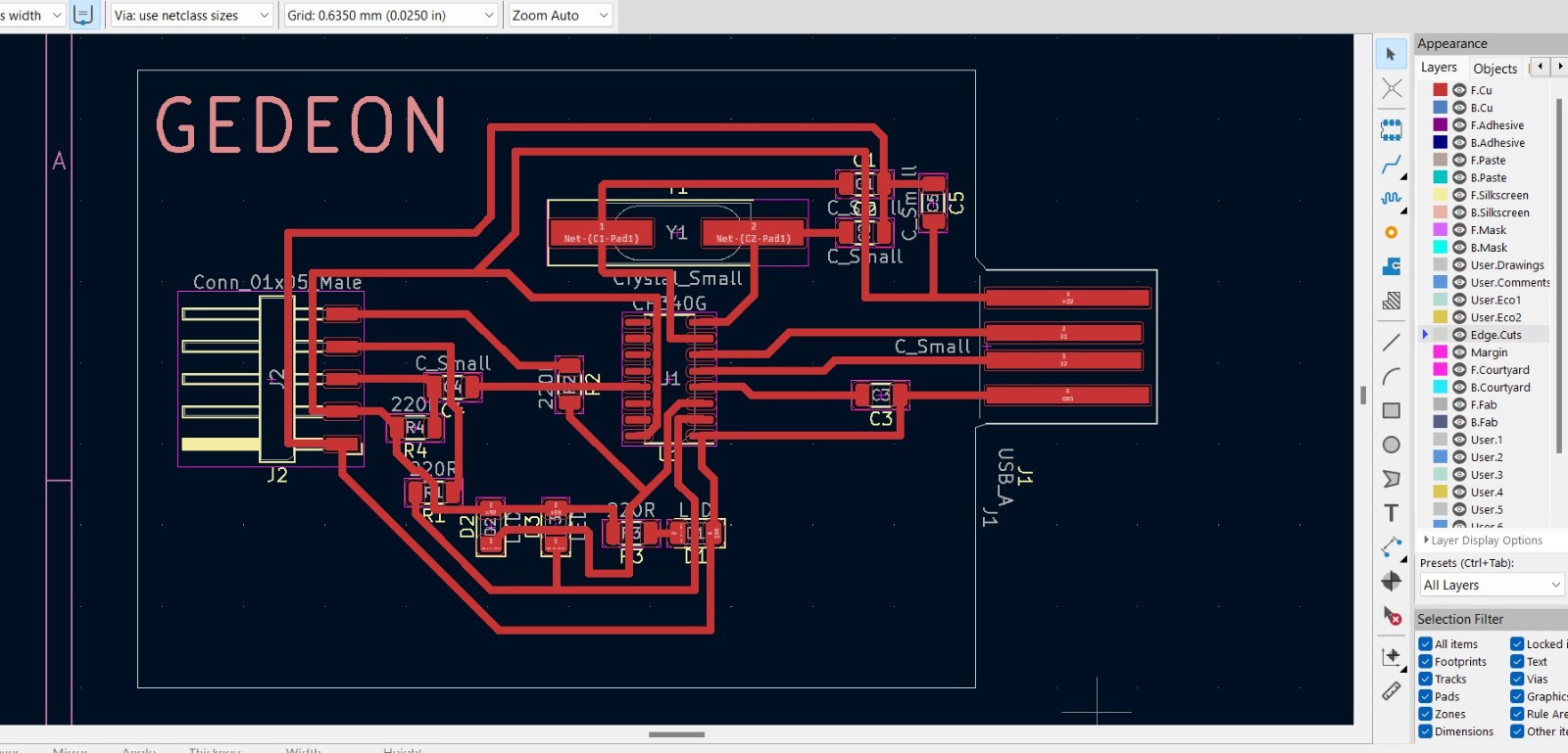
From the schematic design I created a board routing traces manually.
I had to use many dummy resistors to jump over the traces that would otherwise cause problems connecting.
I edited the edge cut to look much more like a USB dongle or something.
 * Generate the Gerber files/ g code
since i was not at the Fab lab i tried using another machine to make the PCB.
this required me to find a way to convert my bord into g-code that this machine would be able to read.
I was trying to us 3018 FoxAlien CNC.
So i downloaded FlatCAM software, installed it on the computer.
I exported from the gerber files and the Excellon ones for the top layer and edge cuts.
I opened the gerber file to the CAM, added in the tool diameter of 0.2536 but when i click on generate geometry,
the software jumps switches it self off; everything disappers.
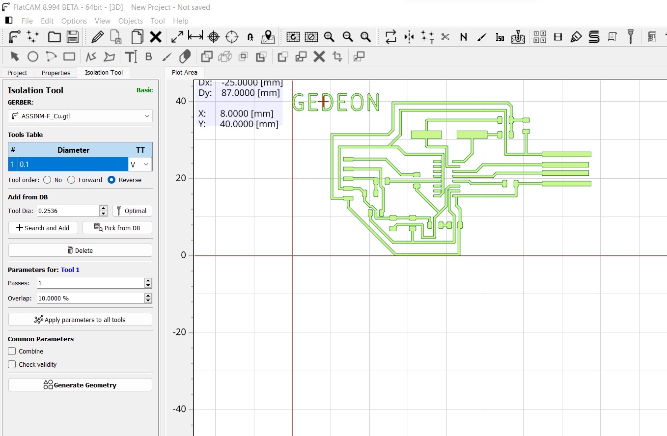 I thought on how to fix the problem; they said (google) that this FlatCAM operates on the winpython. i downloaded it but it did not solve the problem.
I was sfrustrated because this trying took me almost one full day and i did not get any positive results.
I even tried using the Vertic aspire 9.8 to create a tool path and a save it as G code. it worked the machine moved
But since dimensions were off, the result was not good.
if someone knows how to deal with fox alien for PCB, please advise me.
so Mods is the next option for when i get to the Fablab.
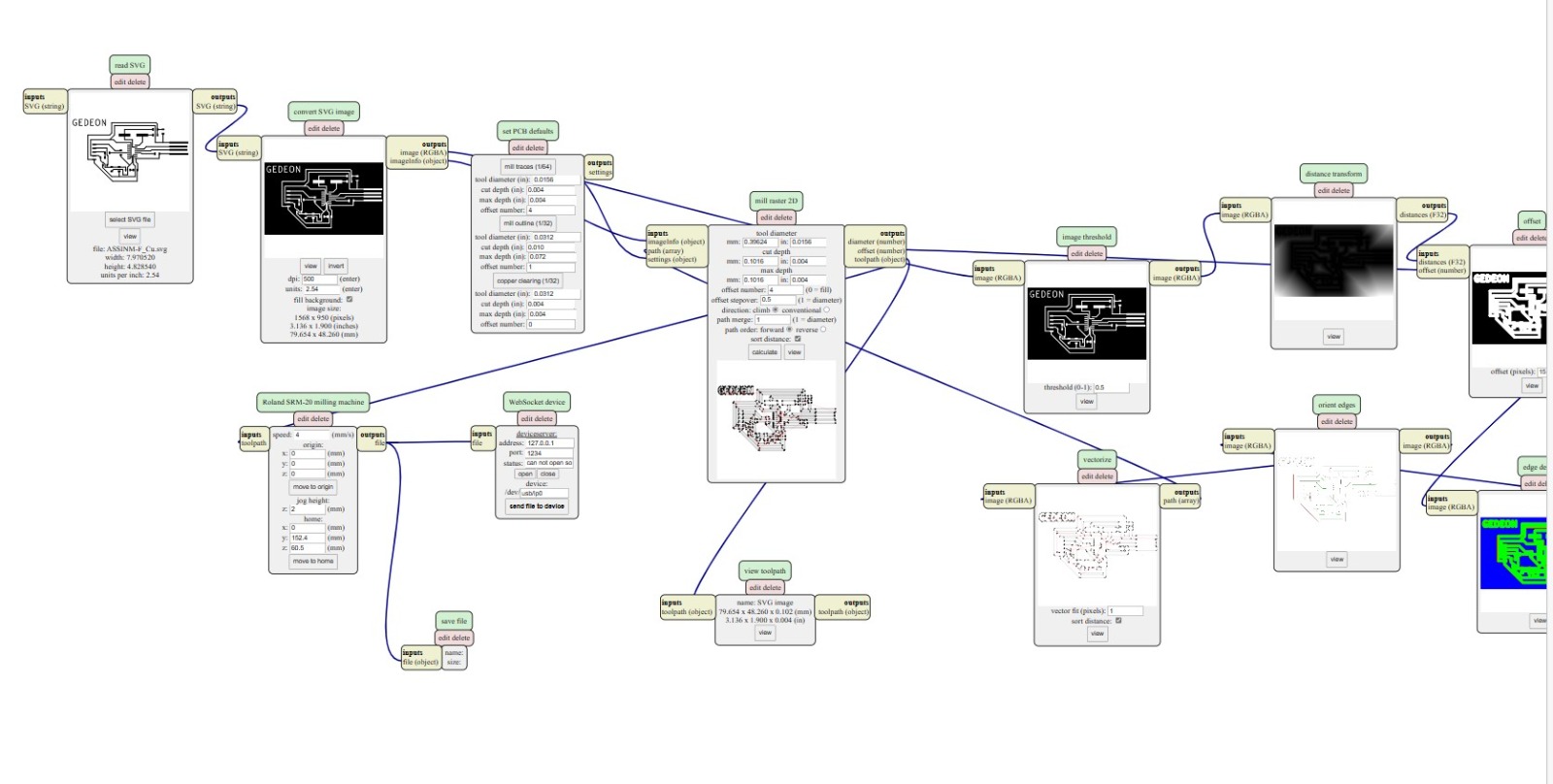 * Mill and cut the PCB
I loaded the .rml file into the SRM20 rolland miller.
Both the mill traces and out cut traces.
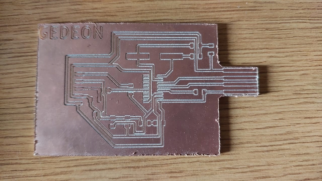 As you see, it came out nice and clean.
* Solder components on the board
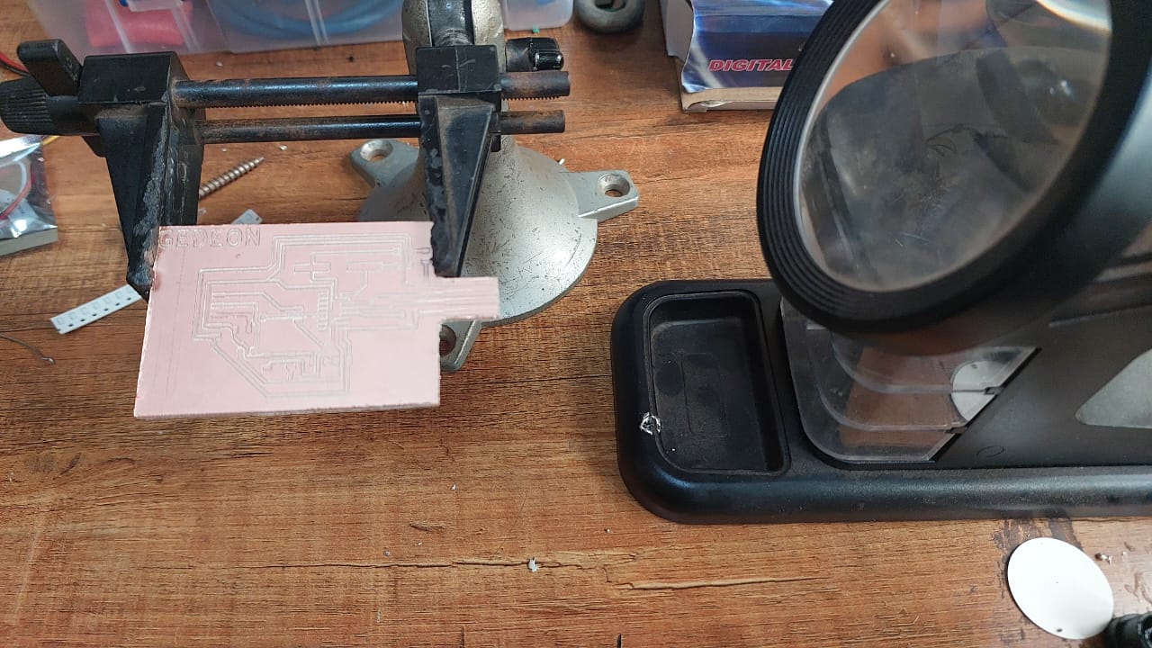 I Used the soldering iron, the lead, and the paste to do the job
This is how it looks halfway done:
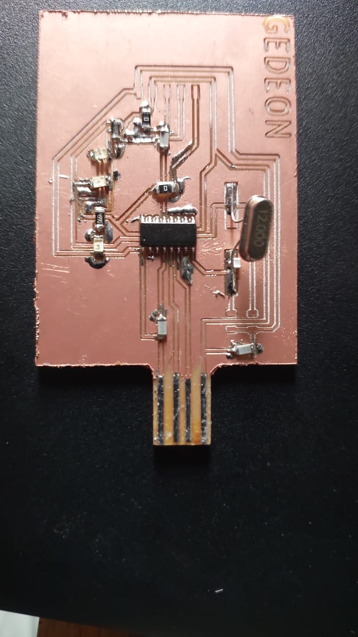 Remaining part:
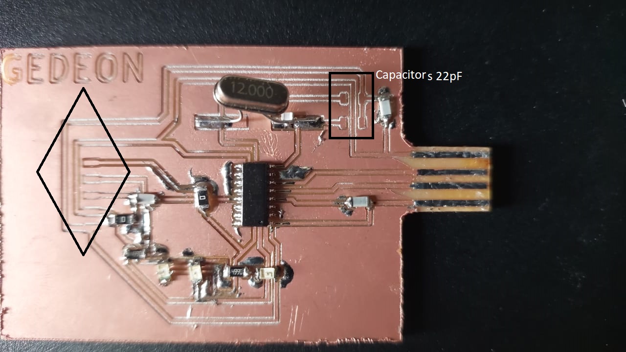 * Connect the USB in the computer and update the drivers
After soldering, i went and downloaded the drivers for CH340G
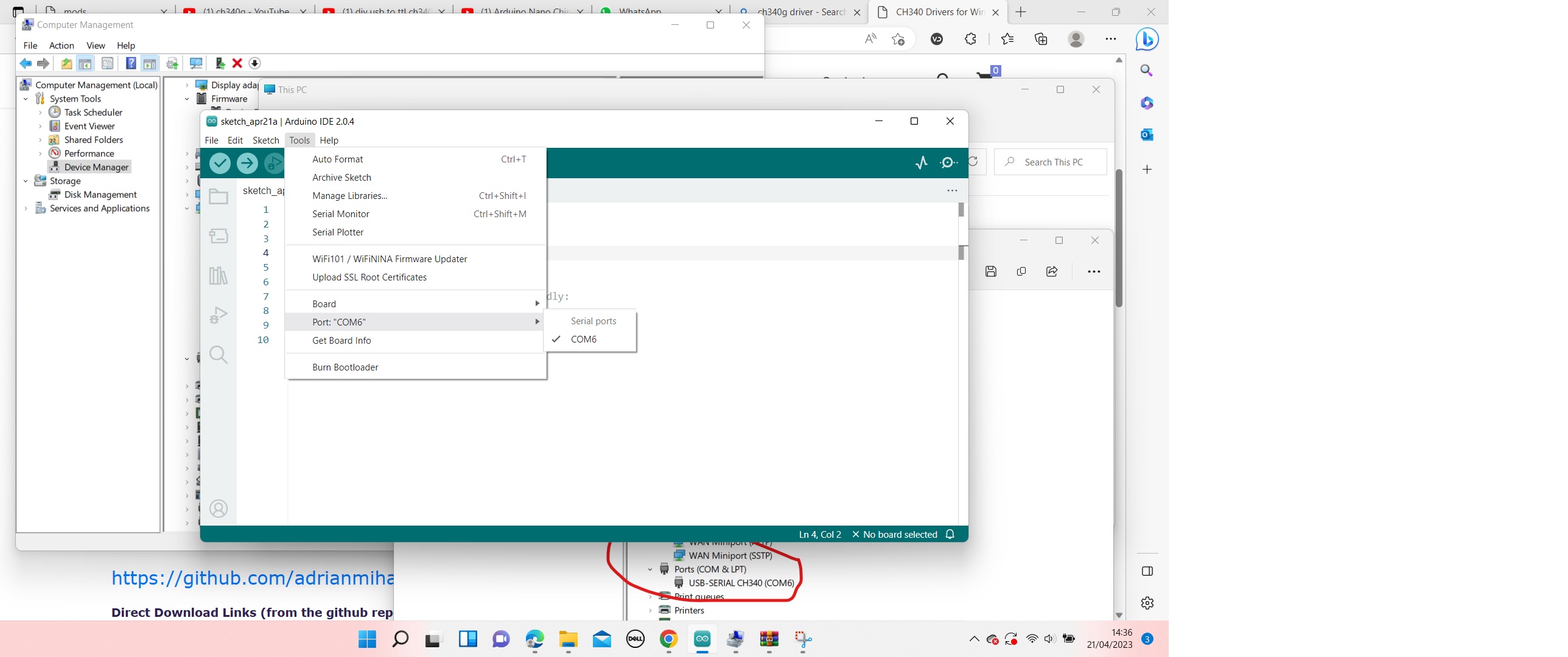
 I installed the drivers and checked the port for arduino IDE to communicate with.
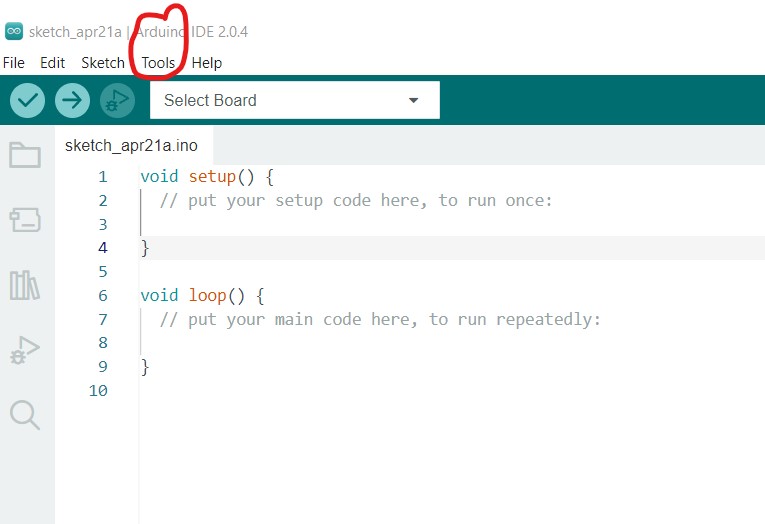
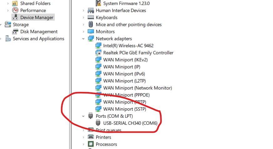 Then i went in arduino IDE environment, on the toolbar, selected tools
I inserted the board into the USB port of the laptop.
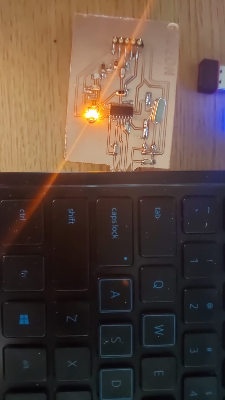 Go back to the Arduino
 Poof!
The com port was found!
 * Test on a computer and send a code to turn on the light
Finally.
Files used:
schematic
Board
Traces in svg
Edge cut in svg
traces gerber
edge cut gerber
the g code that didn't work on the FoxAlien
 the whole data sheet can be found here
However the other interesting thing that i found about this device is:
The pin out diagram:
 There are other steps to make:
* Choose Communication protocol
* List components required
* Design the schematic
* Create a PCB layout
* Generate the Gerber files/ g code
* Mill and cut the PCB
* Sloder components on
* Connect the USB in the computer and update the drivers
* Test on a computer and send a code to turn on the light
Choose Communication protocol:* UART
Why? Because bsed on this website the application of CH340 is to do USB UART conversion.
 we are using the CH340 G as an advanced version of the series.
* List components required
The circuit we are using will comprise following components:


 * Create a PCB layout
From the schematic design I created a board routing traces manually.
I had to use many dummy resistors to jump over the traces that would otherwise cause problems connecting.
I edited the edge cut to look much more like a USB dongle or something.
 * Generate the Gerber files/ g code
since i was not at the Fab lab i tried using another machine to make the PCB.
this required me to find a way to convert my bord into g-code that this machine would be able to read.
I was trying to us 3018 FoxAlien CNC.
So i downloaded FlatCAM software, installed it on the computer.
I exported from the gerber files and the Excellon ones for the top layer and edge cuts.
I opened the gerber file to the CAM, added in the tool diameter of 0.2536 but when i click on generate geometry,
the software jumps switches it self off; everything disappers.
 I thought on how to fix the problem; they said (google) that this FlatCAM operates on the winpython. i downloaded it but it did not solve the problem.
I was sfrustrated because this trying took me almost one full day and i did not get any positive results.
I even tried using the Vertic aspire 9.8 to create a tool path and a save it as G code. it worked the machine moved
But since dimensions were off, the result was not good.
if someone knows how to deal with fox alien for PCB, please advise me.
so Mods is the next option for when i get to the Fablab.
 * Mill and cut the PCB
I loaded the .rml file into the SRM20 rolland miller.
Both the mill traces and out cut traces.
 As you see, it came out nice and clean.
* Solder components on the board
 I Used the soldering iron, the lead, and the paste to do the job
This is how it looks halfway done:
 Remaining part:
 * Connect the USB in the computer and update the drivers
After soldering, i went and downloaded the drivers for CH340G
 I installed the drivers and checked the port for arduino IDE to communicate with.
 Then i went in arduino IDE environment, on the toolbar, selected tools
I inserted the board into the USB port of the laptop.
 Go back to the Arduino
 Poof!
The com port was found!
 * Test on a computer and send a code to turn on the light
Finally.

