Computer-Controlled Machining. Group 1.
Group members
Week 7 group assignment Computer-Controlled Machining
We started with lab's safety training. There was also two videos we were told to watch before local class. Then we continued with the toolpaths. We were explained the basics of toolpath making.
In the machine shop we were shown how to operate local CNC milling machine. First we reviced the safety instructions. You always have to wear safety glasses and hearing protection when operating the machine. Also you must always be well rested and able to focus when milling. Use the machine with a friend, and make sure no one goes too near of the machine. If you do your preparing well and operate the machine carefully, there should be no problems. But if something arises, we were shown the pause and emergency stop buttons.
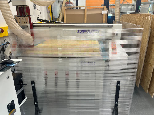
Picture1:CNC milling machine
Our instructor presented us the machine and we went through the following steps:
- First power on the machine and the computer, and then you open the software which is called NC Studio.
- Reset the axels by moving the milling head with either pressing the x and y axis buttons on the program, or with hand wheel device.
- If needed change the tool.
- Set up your piece on the table and attach it.
- Set the origo.
- Load the nc -file.
- Simulate.
- Run the work!
In the group work we used a 6mm, flat milling bit for wood. The milling bit had to be changed, and we watched our instructor to demostrate the changing. You open up 2 switches that hold the casing to the milling bit. You drop it down, and then use two different kind of tools to let loose the milling bit and the socket it is in. Then just change the milling bit and click it back to the socket. It should be spinning around effortlessly. Then just reverse the process and put the tool back in.
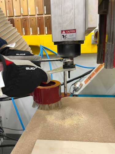
Picture2:Removing the milling bit
Picture3:Dust shoe removed from the spindle
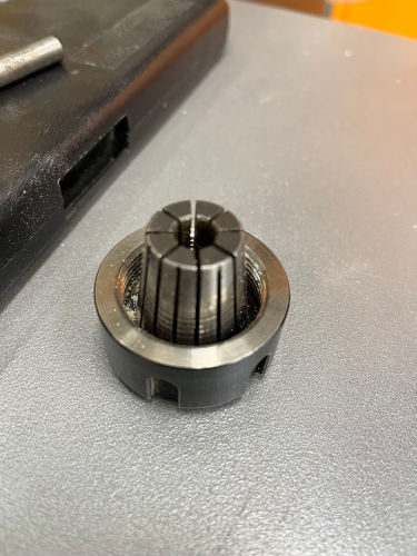
Picture4:Bit holder
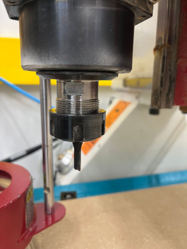
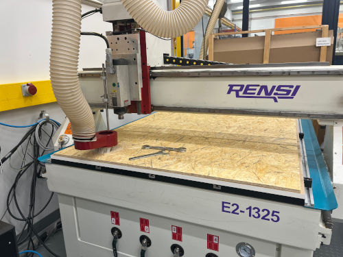
Picture5:Bit in place for milling
Our instructor had a piece of plywood that he wanted to cut 4 shapes of coat hangers from. We noticed that when the material piece isn't very large, it's a bit harder to get it to stick to the cutting board. The big board is divided in to 4 different sections which use vacuum to suck the material down so that it doesn't move during the milling. The switches are found on the edge of the table, and the vacuum pumps are pressed on from the controlling unit. We changed the places and tried to find the best section for the plywood to stick. Material can also be sometimes a bit bent, so you really have search for the best position and alignment on the table.
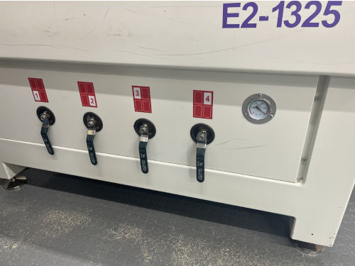
Picture6:Vacuum bed valves
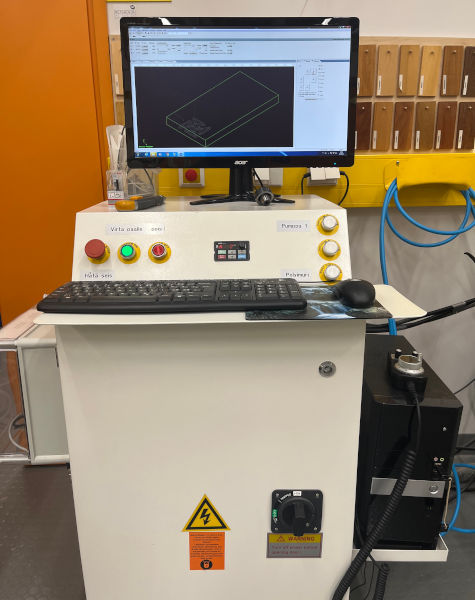
Picture7:Control unit
In the control unit there are for example the power switches, emergency stop, switch for vacuum pump and dust collector, and the computer.
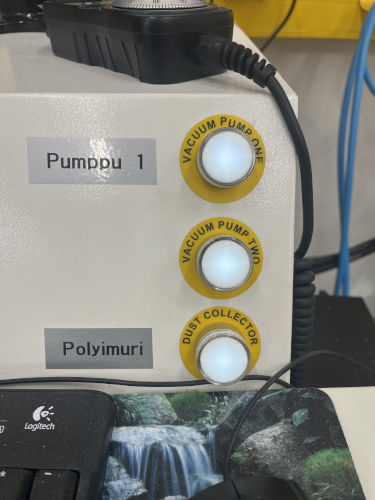
Picture8:Switches for vacuum pumps and dust collector
In NC Studio we learned how to set the axels by moving the milling head buttons on the program and with hand wheel device. We set the origo with x and y axis, and used the mobile calibrating device to set the z also. The file was loaded, vacuum and dust collector were on, so there was nothing else to do but to simulate the process in the program. Everything looked good in the simulation, so the milling could be started.
First the machine milled the pockets. After those it turned on to milling the outlines, and in that point the machine started to make this high pitched noise, almost like a whistle. Our instructor showed us that in that point you must change the spindle speed so that the sound goes down back to normal. You can try and find the optimal speed.
Everything went fine and the pieces were milled beautifully. We were also shown how to clean after the job is done, and for example how to use the sander machine. Then we were off to take the measurements of the cut pieces.
Test piece measurements
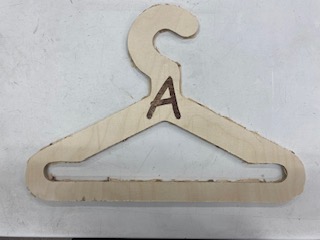
Picture9:Test piece
Table 1 Test piece measurements. Parameters used: for machining speed and spindle feed we used values between 60 % to 100 %. If the machine started whining sound, you knew that you had to adjust speed.
| Test piece | outside width x height | inside opening width x height | bottom beam width | letter A horizontal beam width |
|---|---|---|---|---|
| Design (mm) | 400 x 280 | 348.2 x 88.4 | 26.4 | 8.7 |
| Milled piece (mm) | 399 x 279 | 348 x 88 | 26.6 | 8.7 |