Appearance
Computer controlled machining
This is a very exciting week. We went to Shanghai University of Science and Technology this week and jointed the computer controlled machining training together with our friends from Form Shop there and we do the assignment together. Our mentor Saverio has provide us the training.
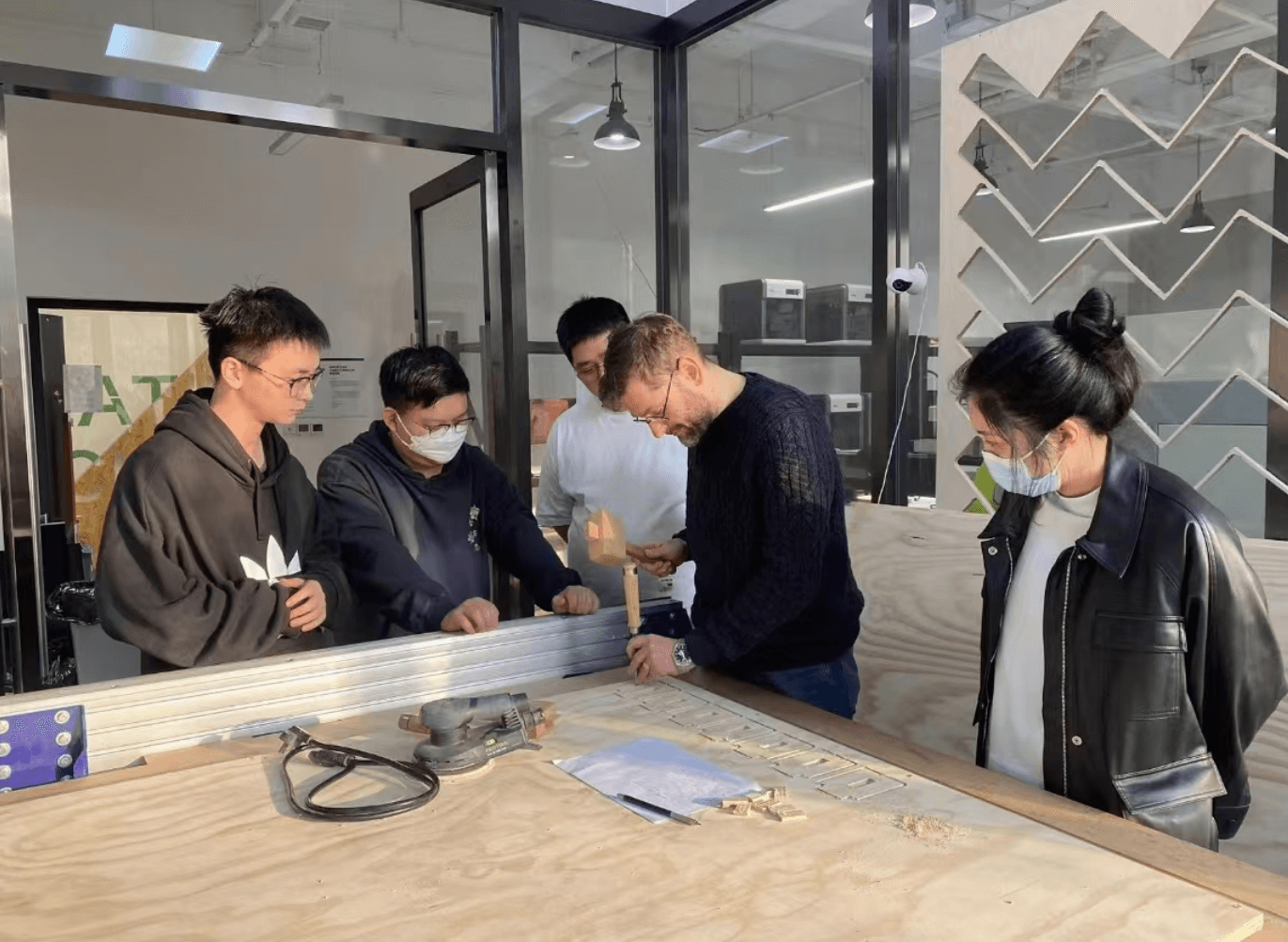
Test the Machine - group work
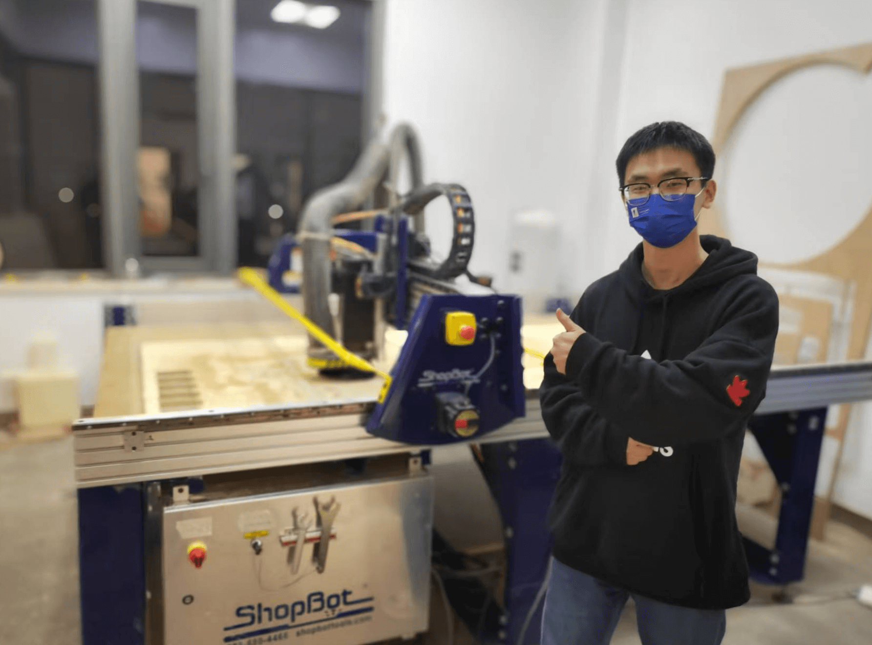
The machine we used for this week is Shopbot. A ShopBot is a type of Computer Numerical Control (CNC) machine used for cutting, carving, and engraving various materials like wood, plastic, and metal. It operates by following a pre-programmed design or pattern, allowing for precise and repeatable manufacturing1. ShopBots are commonly used in woodworking, prototyping, and small-scale manufacturing due to their versatility and accuracy.
Safety precautions
Before,using the machine we did our safety training first.
Restricted Access:
- No one other than the operator should enter while the machine is in operation.
- Do not enter within 1 meter of the machine while it is running.
Personal Protective Equipment (PPE):
- Wear earmuffs, a dust mask, and safety goggles.
- Wear appropriate work clothes, sneakers, or safety shoes. Avoid sandals, high-heeled shoes, or jewelry.
Operator Training:
- Only individuals who have received proper instruction should operate the machine without supervision.
Emergency Preparedness:
- Know the position of the emergency stop switch and how to use it.
Tool and Material Handling:
- Secure the material being cut to prevent movement.
- Regularly inspect cutting tools for wear and damage and replace as needed.
Workspace Maintenance:
- Keep the work area clean and free of debris.
- Ensure that the area around the machine is clear of unnecessary objects.
Machine Settings:
- Double-check program settings before starting the machine to avoid incorrect operations.
Focus and Awareness:
- Avoid distractions and stay focused on the task.
- Be aware of the machine’s operation and surroundings at all times.
Heat and Fire Safety:
- Be aware that rotating tools generate friction and heat, which can be a fire hazard.
Lessons before exercise
Some basic concepts were taught before using machine.
Drill Bit:
- Function: Only drills vertically (downward) without cutting sideways.
- Usage: Ideal for making precise holes without side cutting.
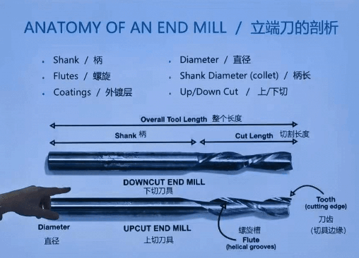
End Mill:
- Function: Capable of cutting with both the sides and the tip (the tool we use).
- Shapes: Available in different shapes, including flat, ball, and V-shaped tips.
- Usage: Versatile for various cutting operations, such as milling, slotting, and profiling.

Shank and Cut Length:
- The diameters of the shank and the cutting portion can vary.
- Importance: Selecting the appropriate shank and cut length ensures stability and precision during machining.
Spindle Rotation:
- The spindle rotates clockwise, affecting the direction of the spiral grooves on downcut and upcut end mills.
- Downcut End Mills: Push chips down and leave a clean upper surface.
- Upcut End Mills: Pull chips up and provide efficient chip removal.
Flute:
- For Wood Cutting: Use end mills with fewer flutes to quickly expel wood chips, reducing fire risk.
- For Metal Cutting: Use end mills with more flutes to efficiently cut through harder materials like metal.
- Flute Count: The number of flutes affects the feed rate and surface finish. Fewer flutes allow for larger chip clearance, while more flutes provide a smoother finish.
Chip Load:
- Definition: Measures the thickness of material removed by each cutting edge during a cut.
- Formula: Chip Load = Feed Rate/(RPM * Number of Flutes)
- Importance: Essential for calculating optimal cutting conditions for different setups, ensuring efficient material removal and tool life.
Feeds and Speeds:
- Feeds: The rate at which the material is fed into the cutting tool, typically measured in inches per minute (IPM) or millimeters per minute (mm/min).
- Speeds: The rotational speed of the cutting tool, measured in revolutions per minute (RPM).
- Importance: Proper feeds and speeds are crucial for efficient and safe CNC machining, depending on the material and the tool being used. They affect the quality of the cut, tool life, and overall machining performance.
Additional Considerations:
- Material Type: Different materials (e.g., wood, aluminum, steel) require different tool types, feeds, and speeds.
- Tool Wear: Regular inspection and replacement of worn tools maintain machining accuracy and prevent damage.
- Coolant: Using coolant can reduce heat generation, prevent tool wear, and improve surface finish.
- Workholding: Securely fastening the workpiece prevents movement and ensures precision during machining.
Performance test
We have test the different feed speed, spindle speed and cut depth with our machine.
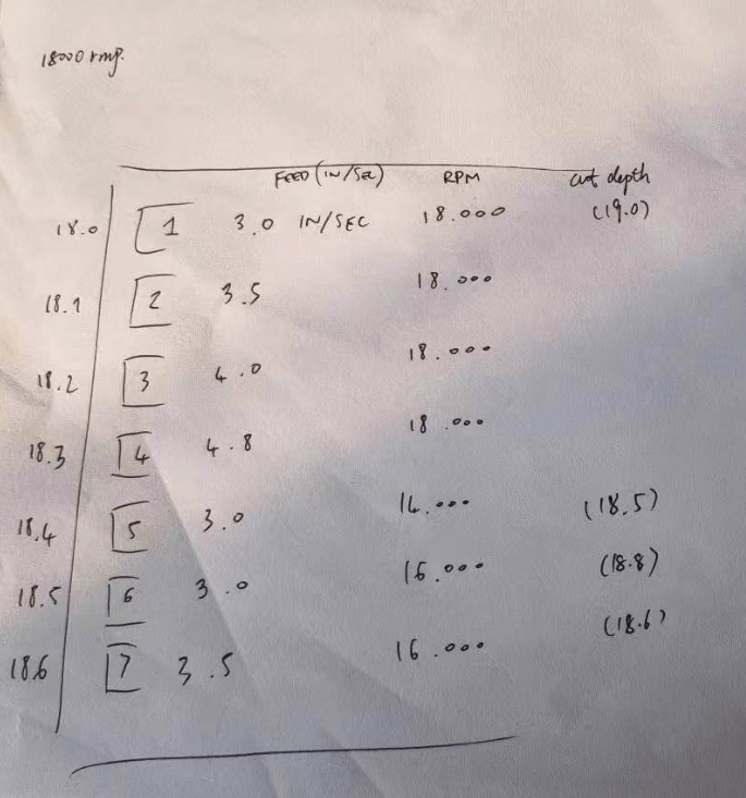
From the chipload point of view, there is not much difference. 16k RMP with 3.5 in/sec is slightly better.

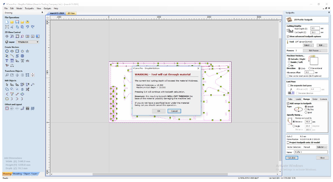
Besides, the best joint for our 18mm plywood board is 18.5mm.

CAD Design in Fusion 360
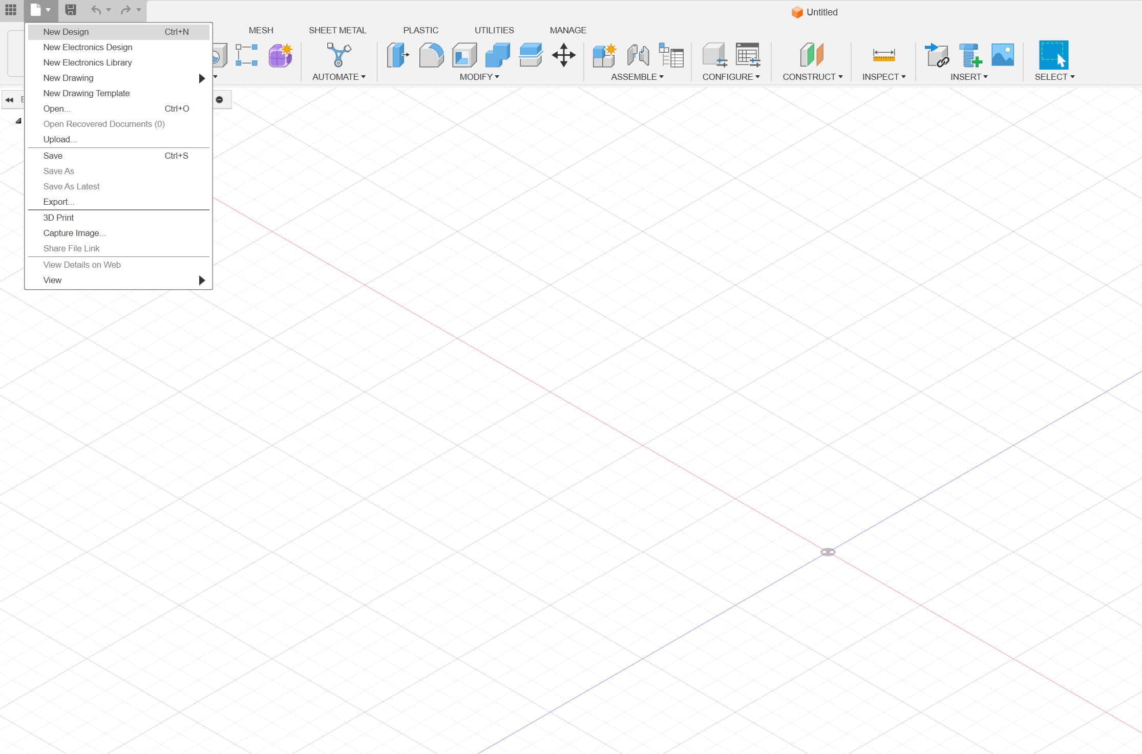
Create a new drawing.
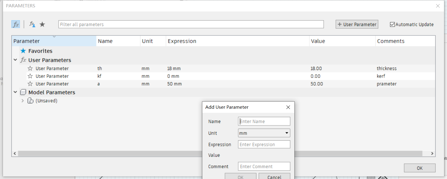
Set user parameters before design, these parameters can be easily used in further designs.
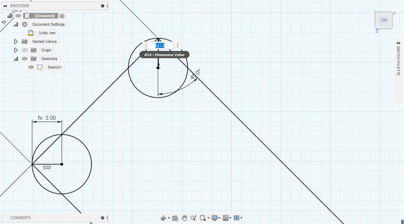
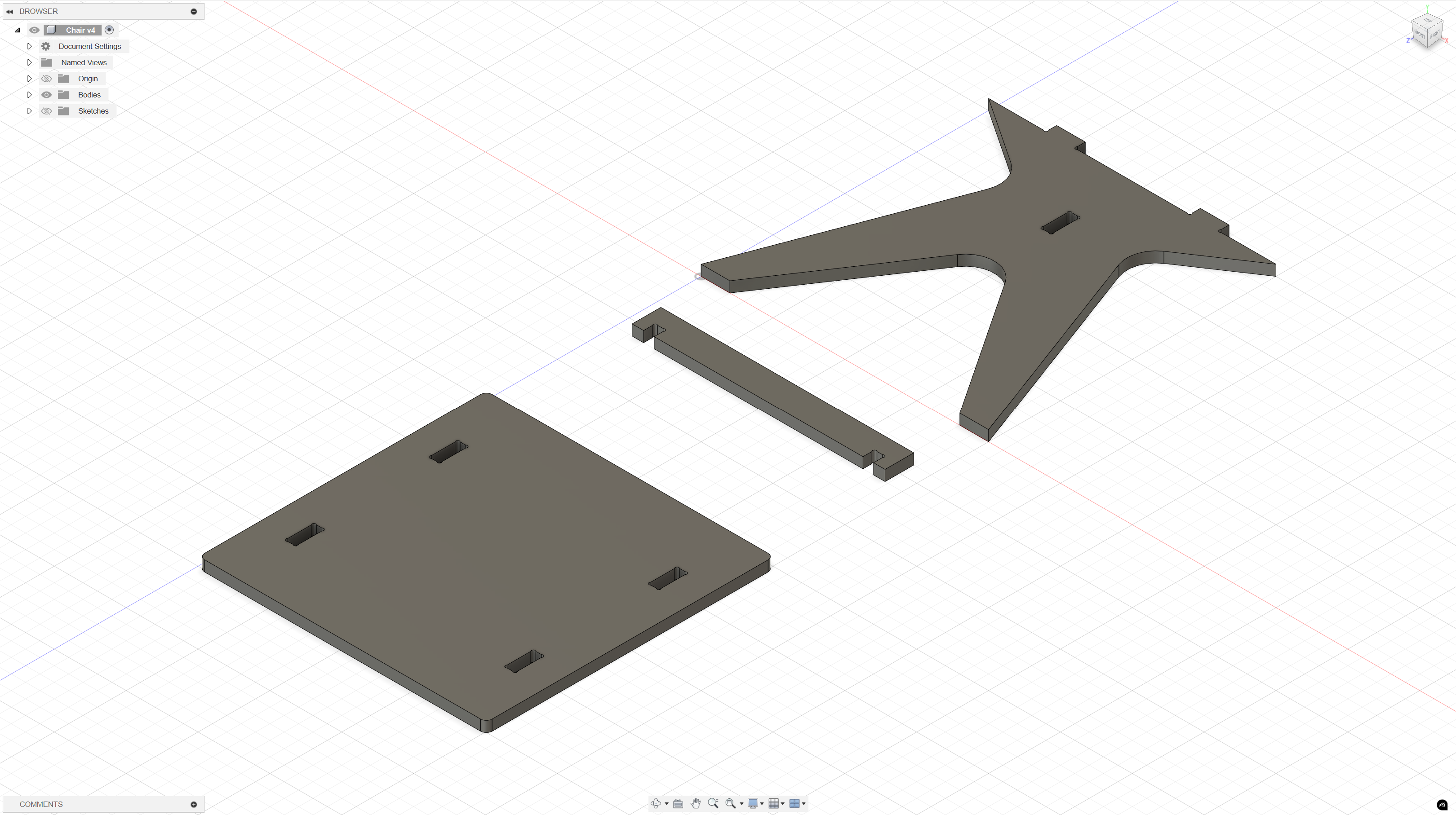
Use the parameter in design for cutting the dogbone shape for the hollows on desk supporter. The dogbone shape is used in CNC design to facilitate the assembly of wooden parts.
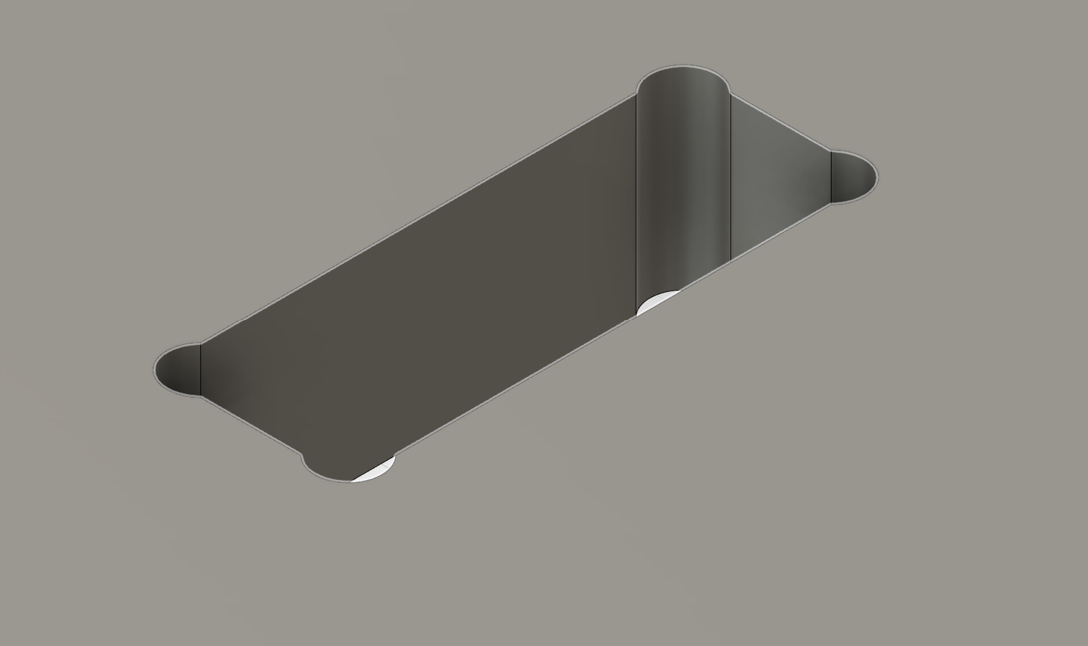
Use the parameter in design for plate thickness of the desk supporter.
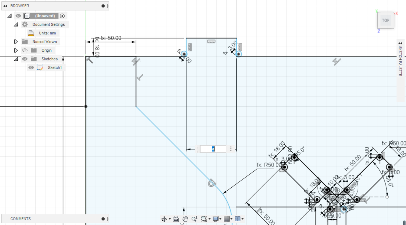
Design the desk surface and connecter
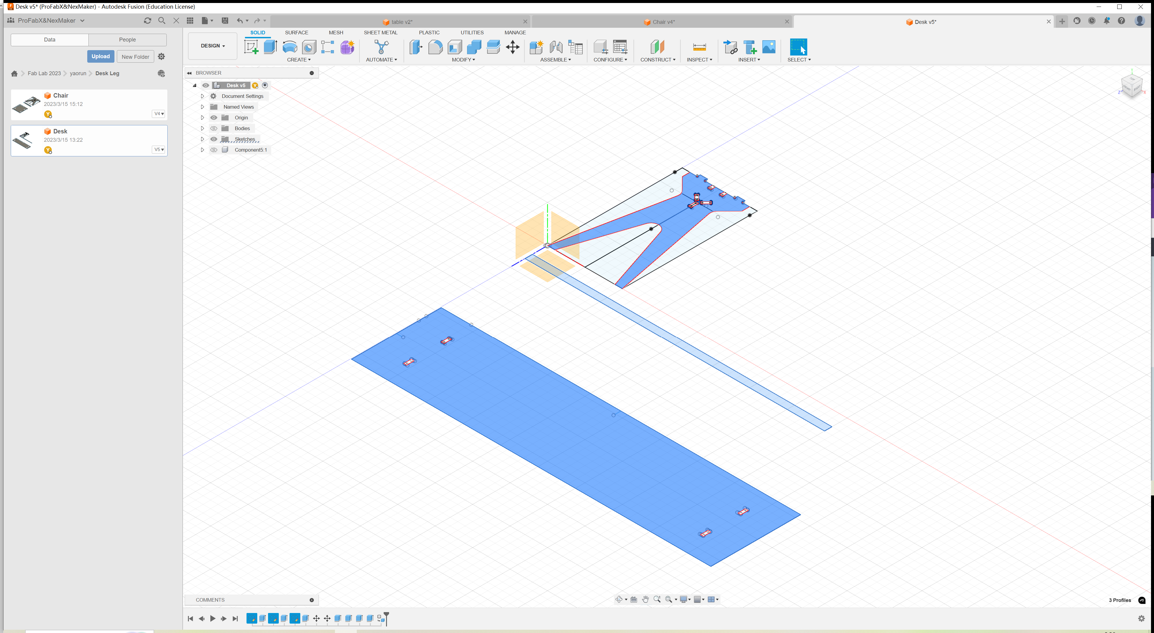
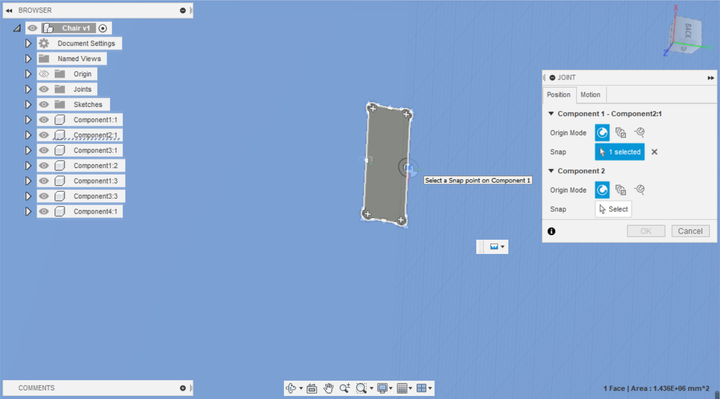
Assemble the designed part using joint function in the Fusion.
Overall performance of the assembled part.
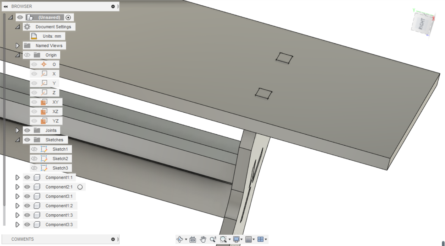
3D version Desk.
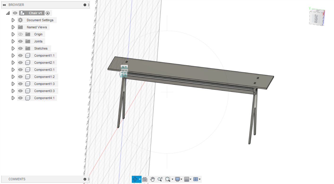
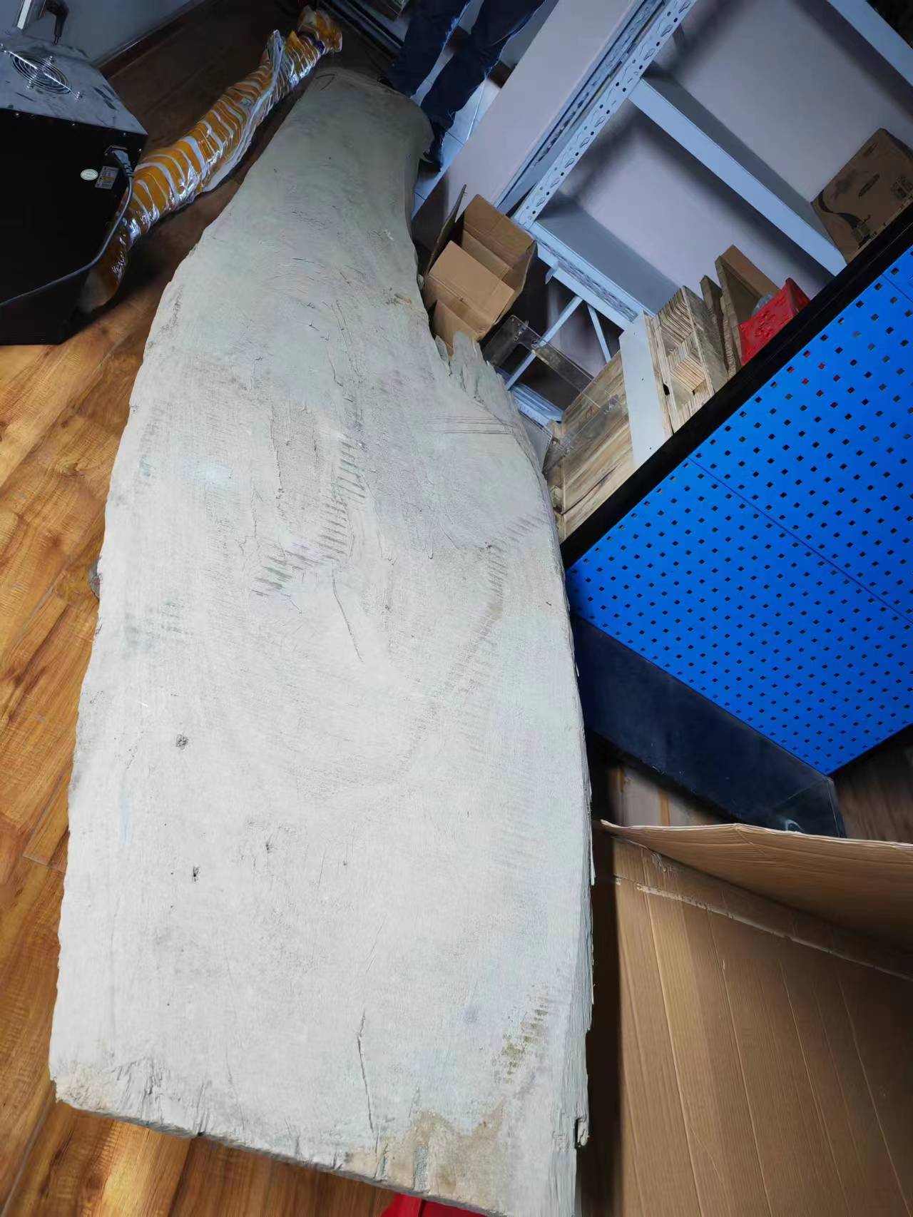
We plan to use this piece of waste wood broad with resins as the desk surface in the molding and casting session. Therefore we will not waste material on cutting the desk top.
Another little desk was also designed.
CAM design - VCarve setups
This part shown the VCarve setup process.
Step 1: New Job Setup
Enter the appropriate parameters for the size of the plywood.
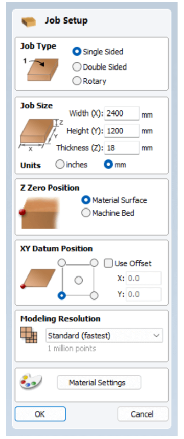
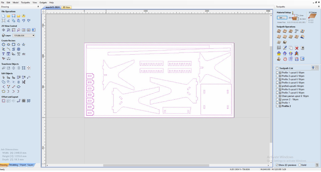
Step 2: Import DXF File
Import the DXF file. Properly arrange your works can help you save space for your own materials.
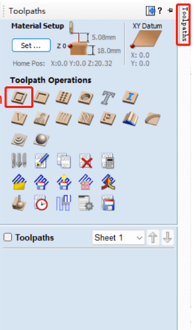
Step 3: Generate Toolpaths
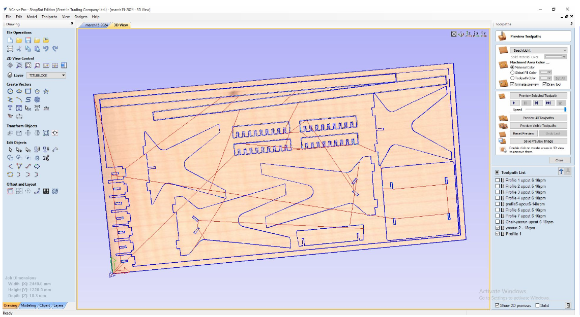
Generate the profile toolpath.
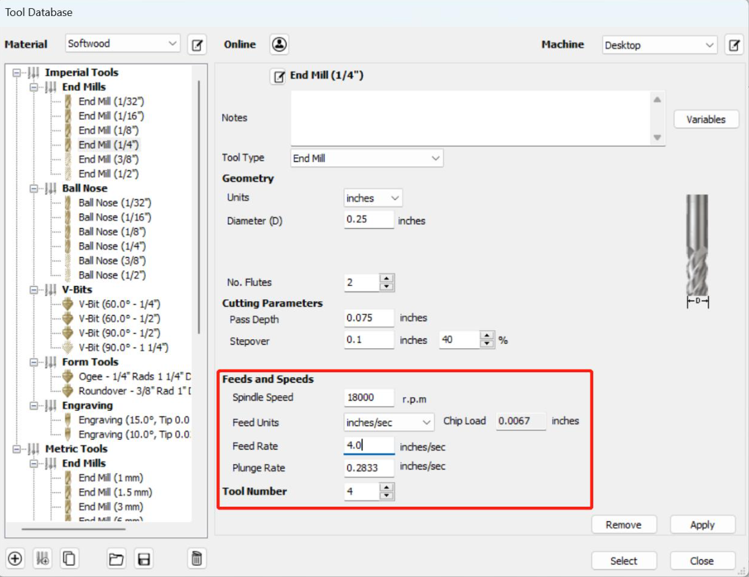
Step 4: Select Tool
Click "Select" in the tool tab and choose a 1/4" end mill with a spindle speed of 16,000 RPM and a feed rate of 3.5 inches per second.
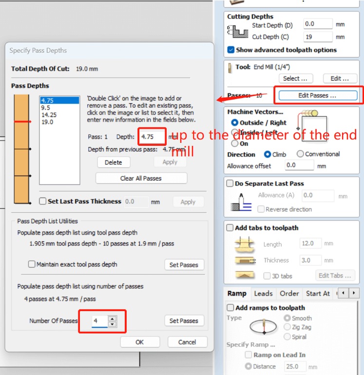
Step 5: Edit Passes
Click "Edit Passes" at the bottom of the tool tab. Set it to 4 passes with a depth of 4.75mm per pass.
Step 6: Specify Ramp
Choose a smooth ramp and set the distance to 25mm.

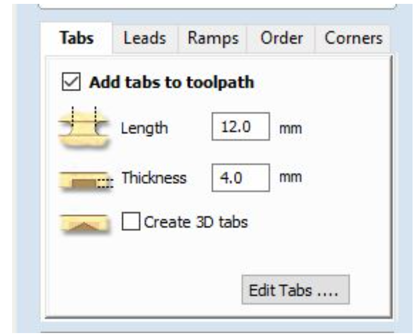
Step 7: Add Tabs
Click "Add Tabs to Toolpath" and then "Edit Tab". Manually add tabs along the path. Setting the type and size of bone connection.
Step 8: Calculate and Save Toolpath
Calculate and see saved the toolpath.
Cutting with ShopBot
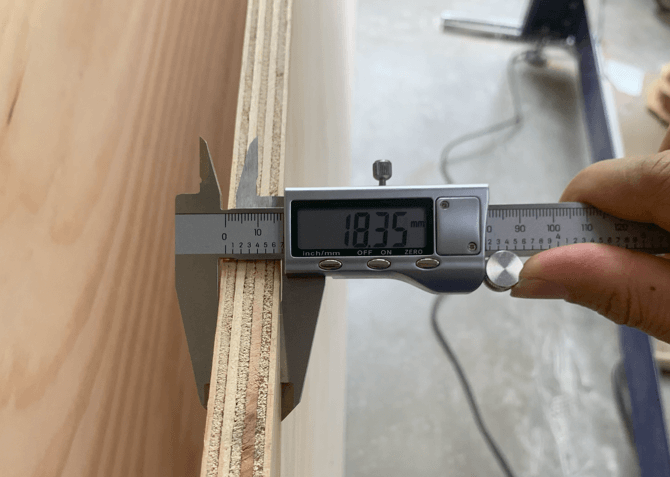
Measure the board thickness.
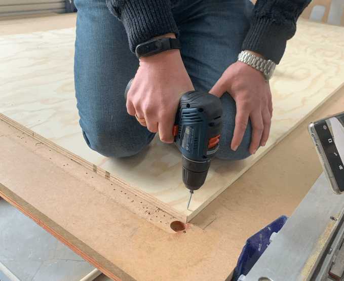
Stable the board with screws.
Present a initial cutting point calibration, including XYZ directions.
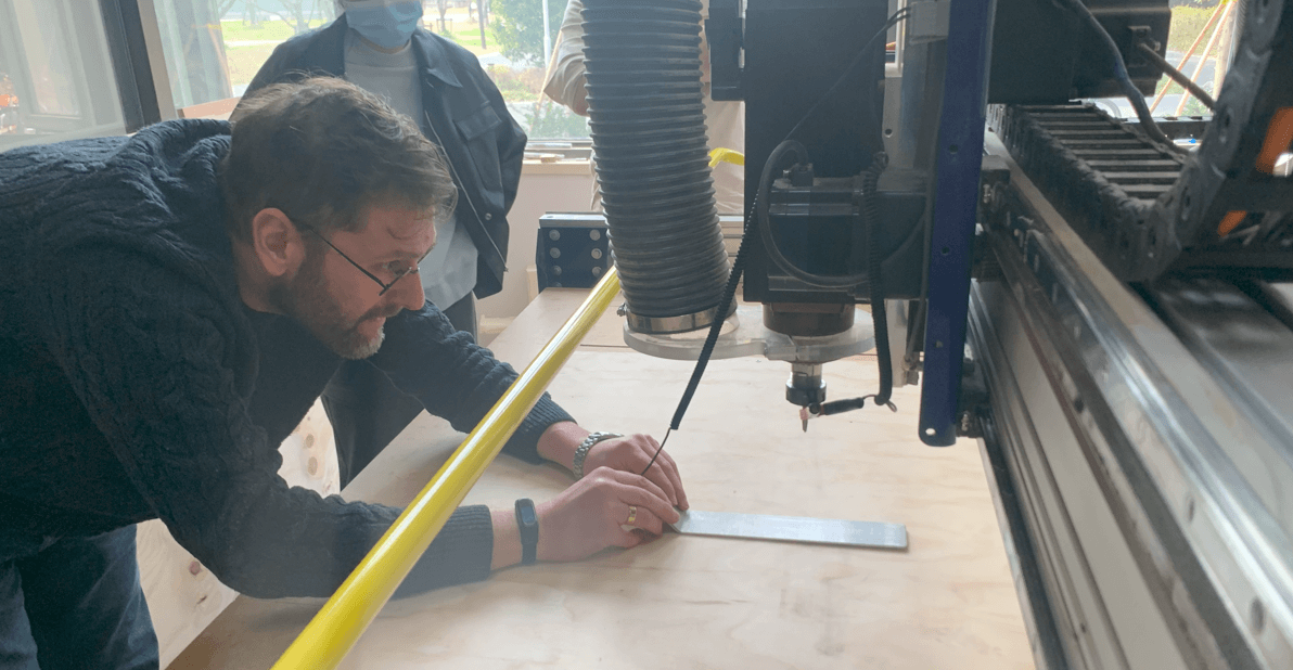
The video here provide a overview of the cutting process.
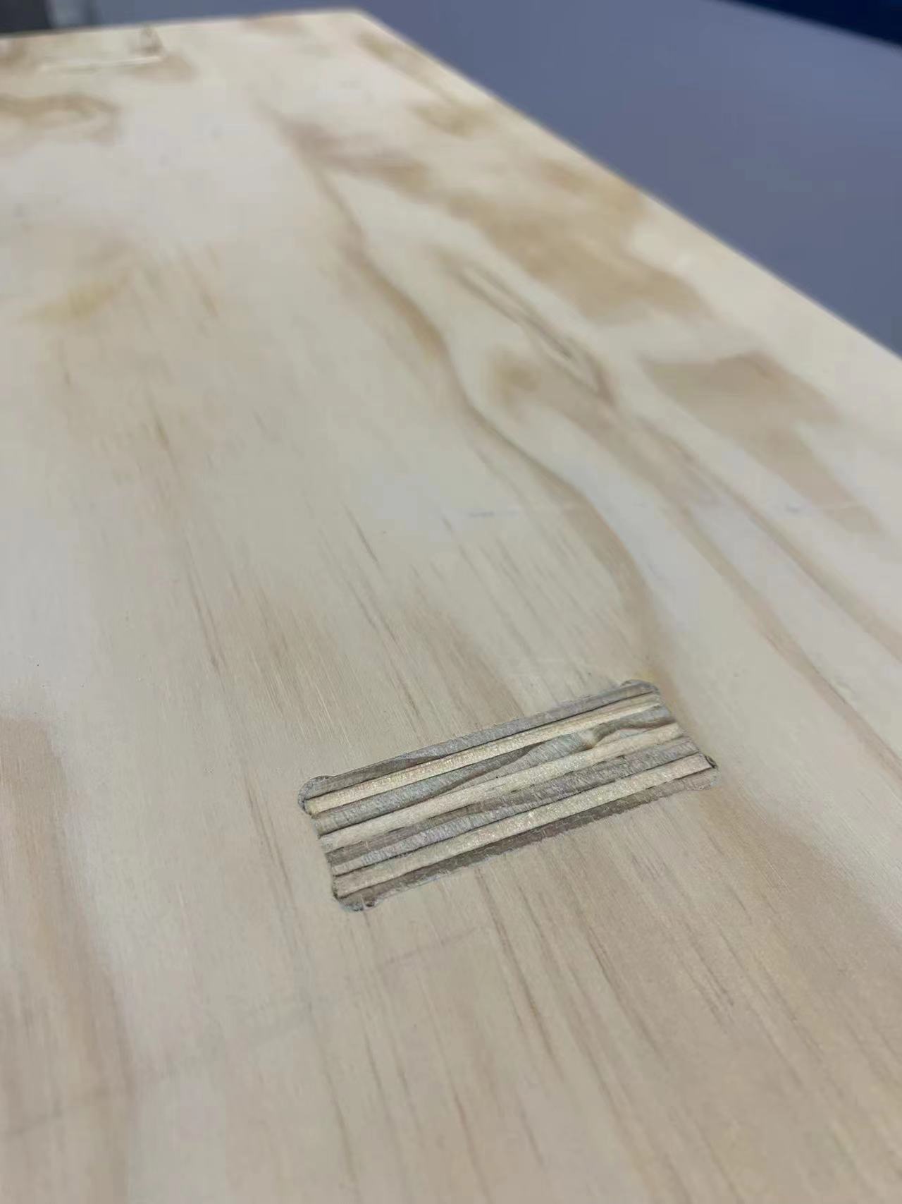
Due to the machine's bed not being level, a defect was generated.
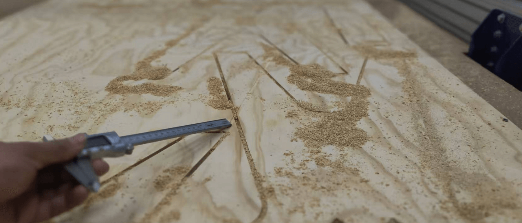
Final result.
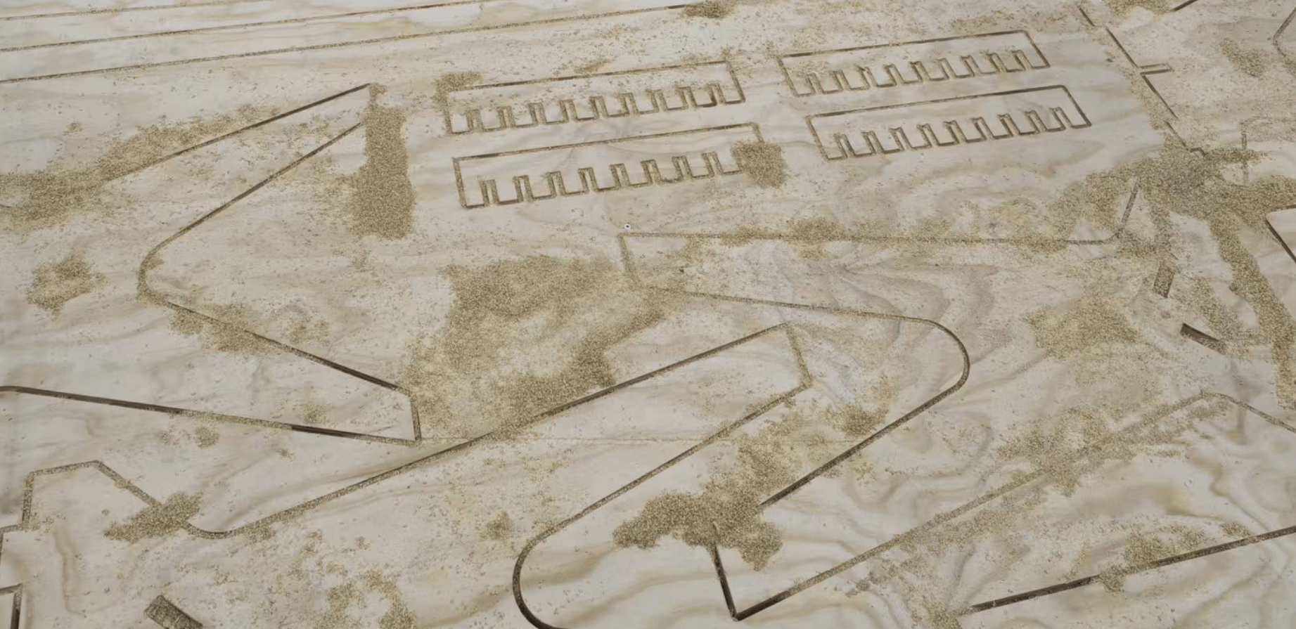
Assemble the Broads
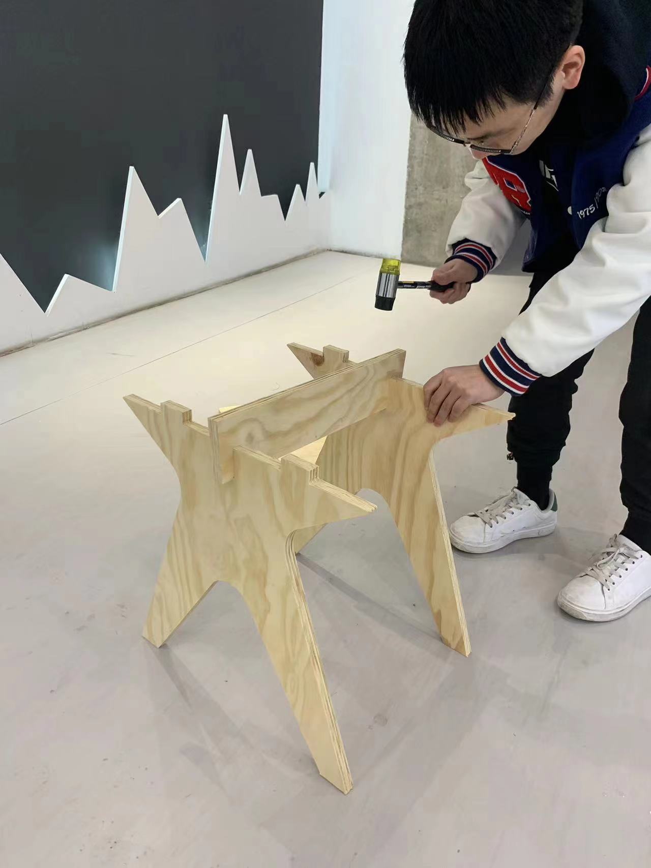
Here I have assembled the machined boards to a table. It start with the supporter.
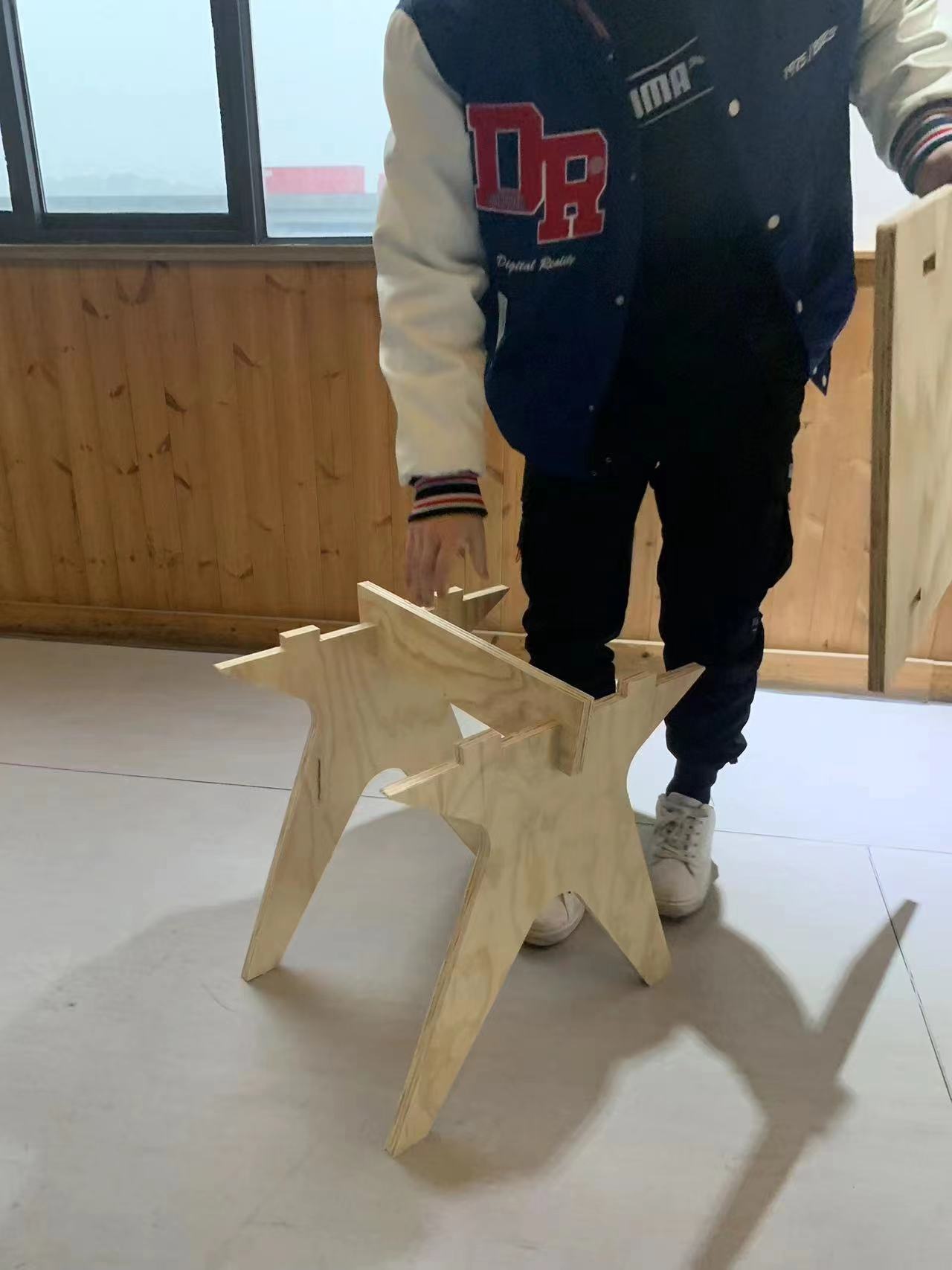
Using a rubber mallet to assemble the wooden parts is more suitable。
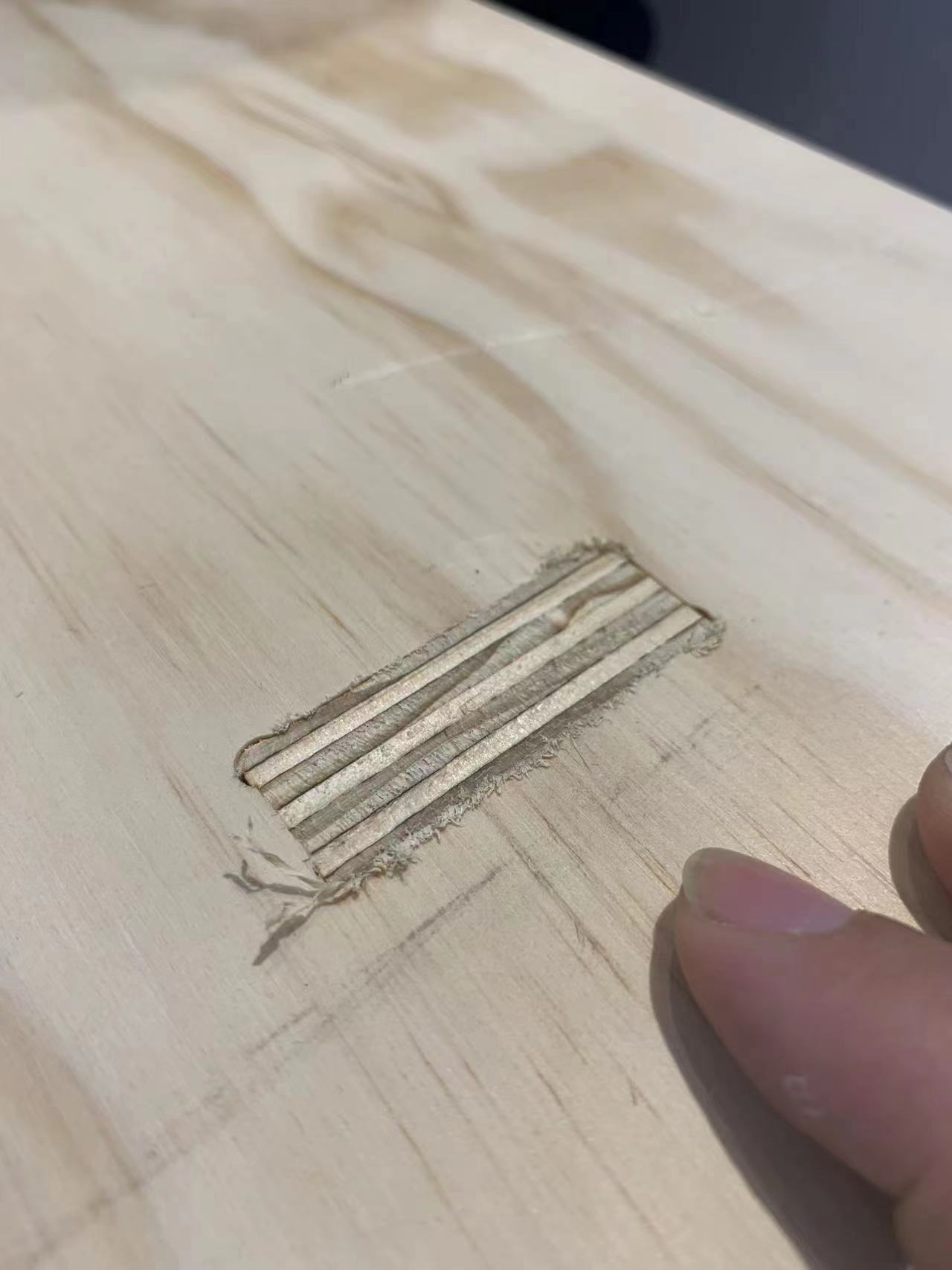
During the machining and assembly process, some wood splinters may be generated.
Use fine sandpaper to gently smooth out the areas with splinters.
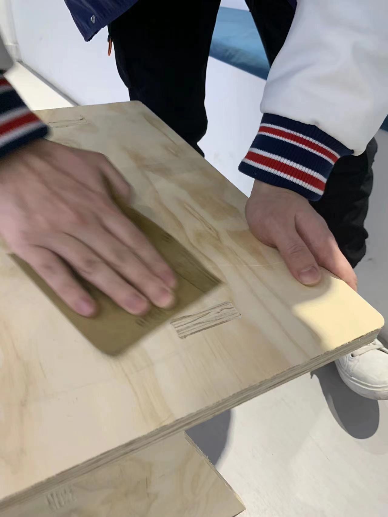
After sanding the surface became smooth.
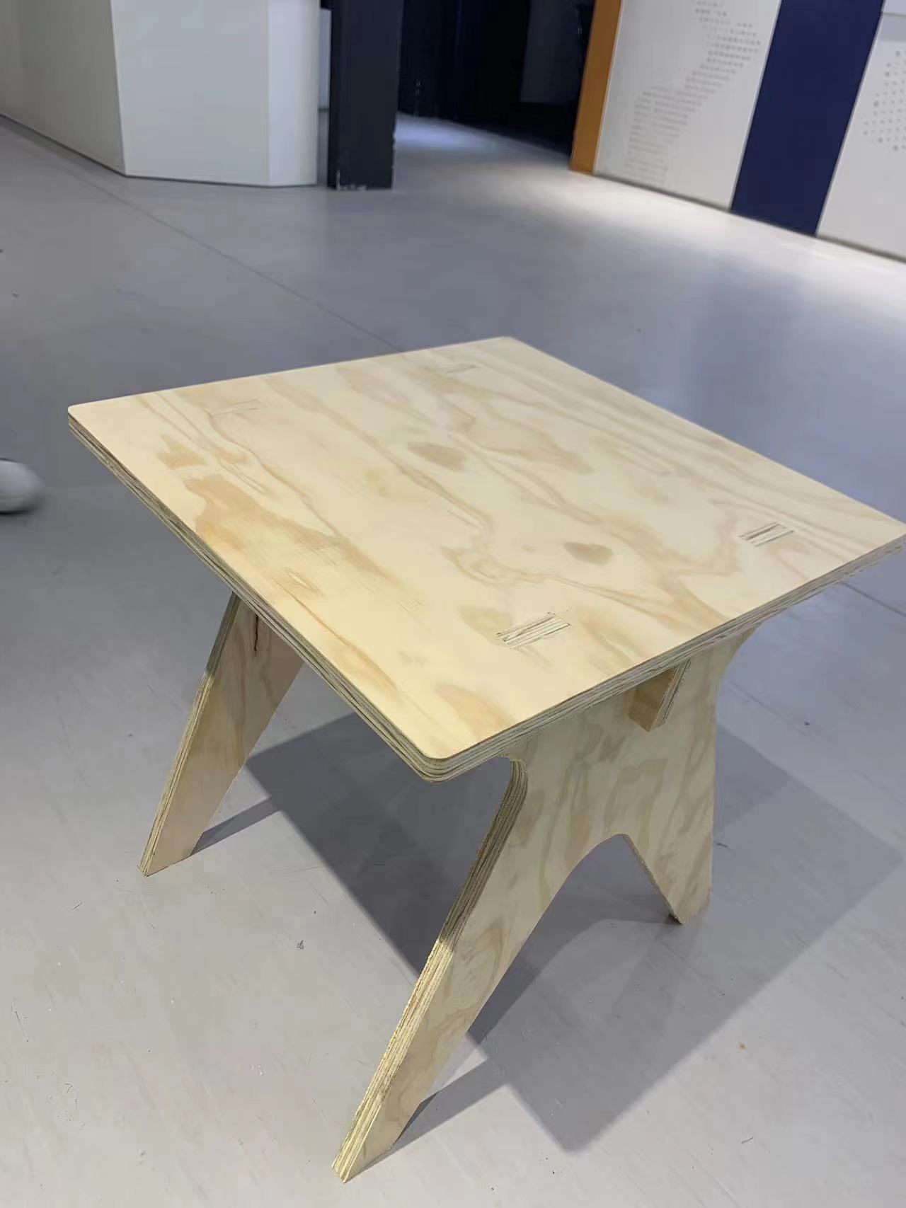
A hero shot of the little table is presented here.
Reference
All original design files can be found at my repo (https://gitlab.fabcloud.org/academany/fabacademy/2023/labs/ningbo/students/yaorun-zhang/-/tree/main/docs/assignments/week7/pic-week7?ref_type=heads).