Appearance
Networking and Communications
This week, I did two projects related to the networking and communications.
- Try send message between a Arduino UNO and a Raspberry-Pi.
- Try wifi connection between a Seeed Studio XIAO and a Raspberry Pi.
Group Work 2025 - Communication between two XIAO-ESP32C3 with wire UART connection
Assignment: Send a message between two projects. This section I and Xu have tried to send a message between two ESP32-C3 board with UART connection. One board (Master) sends a message "ON" to the other board (Slave), which turns on an LED upon receiving the command.
Materials Needed
- 2× ESP32-C3 boards
- 1× LED
- 1× Resistor (220Ω recommended)
- Breadboard and jumper wires
- USB cables (for both boards)
- Arduino IDE
Circuit Setup
Slave Board (Receiving Side):
- Connect LED anode (longer leg) to GPIO 2 through a resistor
- Connect LED cathode to GND
Wiring Between Xiao-ESP32 Boards: - Master TX → Slave RX
- Master RX → Slave TX
- Master GND → Slave GND
Master Code (Sender - Board 1)
void setup() {
  Serial1.begin(9600, SERIAL_8N1, 20, 21); // RX=20, TX=21(D7, D6)
}

void loop() {
  Serial1.write('a'); // led on
  delay(4000);
  Serial1.write('b'); // led off
  delay(4000);
}
Slave Code (Receiver - Board 2)
#define led1 D2
// #define led2 9
// #define led3 10

void setup() {
  Serial.begin(115200);
  Serial1.begin(9600, SERIAL_8N1, 20, 21);  // RX=20, TX=21(D7, D6)
  pinMode(led1, OUTPUT);
  digitalWrite(led1, LOW);
}

void loop() {
  while (Serial1.available()) {
    char c = Serial1.read();
    Serial.print("Received: ");
    Serial.println(c);

    if (c == 'a') {
      digitalWrite(led1, HIGH);
      Serial.println(c);
      delay(1000);
    } else {
      digitalWrite(led1, LOW);
      delay(1000);
    }

  }
}
Steps to Execute
- Connect the Boards: Use jumper wires to connect TX of Master to RX of Slave, and GND to GND.
- Upload Master Code: Connect Master board to PC and upload the master sketch.
- Upload Slave Code: Connect Slave board to PC and upload the slave sketch.
- Power the Boards: You can power both via USB or an external power source.
- Observe the Result: The LED on the Slave board will blink once every 2 seconds upon receiving the "ON" command from the Master.
Video 2025
The result is shown as video below.
Group Work 2023 - Communication between a Arduino UNO and a Raspberry-Pi
In this part, I connect an Arduino to a Raspberry Pi and have the Arduino send "Hello from Arduino" to the Raspberry Pi, which will blink an LED upon receiving the command from the Arduino.
Materials Needed:
- Arduino
- Raspberry Pi
- USB cable
- LED
- Resistor
- Breadboard and wires
Steps for communication:
Connect the LED to Pin 11: Connect the longer leg (anode) of the LED to GPIO pin 17 on the Raspberry Pi. Connect the shorter leg (cathode) to a resistor and then to the ground (GND).
Set Up the Raspberry Pi:
Open Python 3 in a new window on the Raspberry Pi. Write and save the following code:
import serial
import RPi.GPIO as GPIO
import time

# Initialize serial communication with Arduino
ser = serial.Serial("/dev/ttyACM0", 9600)
# change ACM number as found from ls /dev/tty/ACM* The ACM number refers to the specific device identifier for a USB-connected serial device on a Unix-like operating system, such as Linux or macOS. When you connect a USB device to your computer, it is assigned a unique identifier like /dev/ttyACM0, /dev/ttyACM1, etc. The number at the end (0, 1, etc.) increments based on the order in which devices are connected.
ser.baudrate = 9600

# Define a function to blink an LED
def blink(pin):
    GPIO.output(pin, GPIO.HIGH)  # Turn the LED on
    time.sleep(1)                # Wait for 1 second
    GPIO.output(pin, GPIO.LOW)   # Turn the LED off
    time.sleep(1)                # Wait for 1 second
    return

# Set up GPIO using Board numbering
GPIO.setmode(GPIO.BOARD)
GPIO.setup(17, GPIO.OUT)  # Set pin 17 as an output pin

# Main loop
while True:
    # Read a line from the serial input
    read_ser = ser.readline().decode('utf-8').strip()
    print(read_ser)  # Print the received message
    # Check if the received message matches "Hello From Arduino!"
    if read_ser == "Hello From Arduino!":
        blink(17)  # Blink the LED connected to pin 17
Set Up the Arduino: Open Arduino IDE and upload the following code to Arduino:
String data = "Hello From Arduino!";

void setup() {
    Serial.begin(9600);
}

void loop() {
    Serial.println(data);  // data that is being Sent
    delay(200);
}
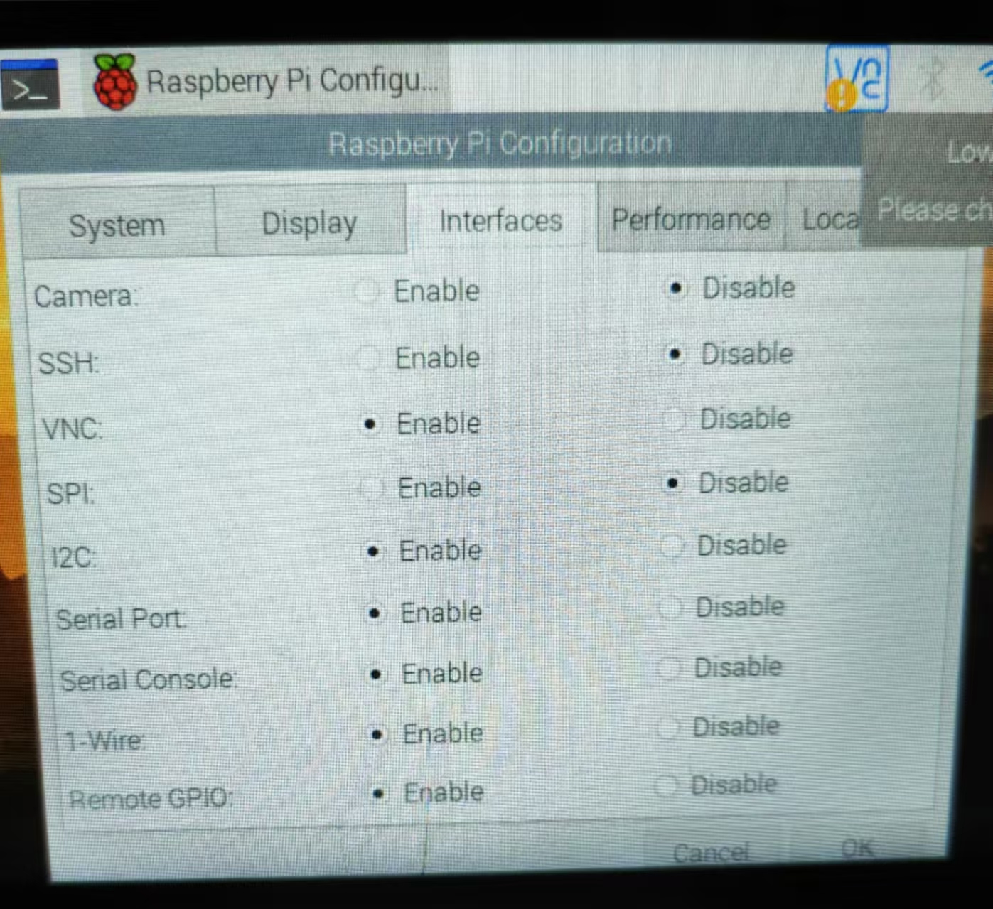
Enable Serial and I2C on Raspberry Pi: Open raspi-config and enable both Serial and I2C interfaces.

Install Required Libraries:
sudo apt-get install python-serial
sudo pip install pyserial
Connect Arduino to Raspberry Pi: Use a USB cable to connect the Arduino to the Raspberry Pi. Execute ls /dev/tty* in the terminal and find a line like /dev/ttyACM0 or similar.
Update the Python Code: Update the line ser = serial.Serial("/dev/ttyACM1", 9600) to match the ACM number you found, e.g., ser = serial.Serial("/dev/ttyACM0", 9600)
Run the Python Program: Now run the Python program you created. You should see "Hello From Arduino!" in the Python terminal, and the LED should blink!
Video 2023
The result is shown as video below.
Wifi connection between a Seeed Studio XIAO and a Raspberry Pi.
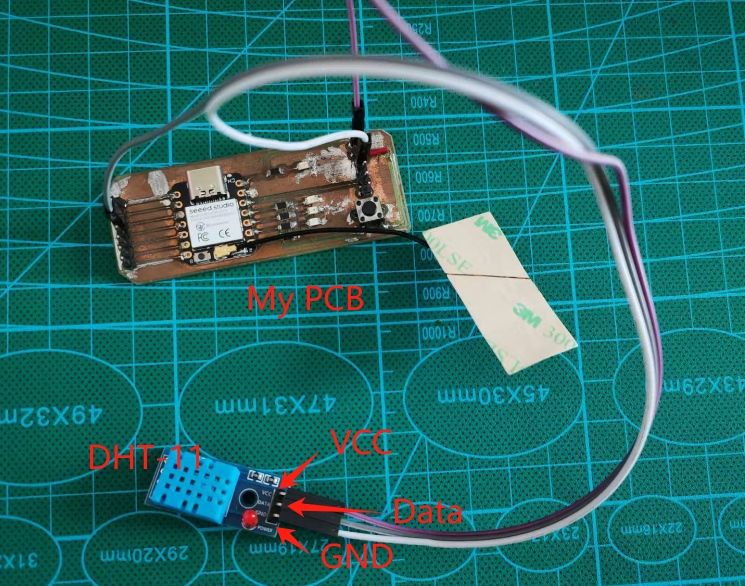
In this part I have connect a DHT-11 temperature & humidity sensor to the Seeed Studio Xiao ESP32C3 extension board I made previously and sending the data to a Raspberry Pi through WIFI connection.
Temperature & humidity sensor DHT-11
The DHT-11 sensor is a popular digital temperature and humidity sensor used in various DIY electronics projects. It's widely used in applications like remote weather stations, home automation projects, and plant monitoring systems.The sensor consists of two main components: a capacitive humidity sensor and a thermistor for temperature measurement. It outputs a digital signal that can be read by a microcontroller, such as an Arduino2. Key points about the DHT-11 sensor:
- Temperature Range: 0°C to 50°C
- Humidity Range: 20% to 80%
- Accuracy: ±2°C for temperature, ±5% for humidity
- Sampling Rate: 1Hz (once every second)
- Power Consumption: 2.5mA during measurement

Code for reading signals from DHT-11':
#include <DHT.h>

// Define the pin and type for the DHT sensor
#define DHTPIN A2
#define DHTTYPE DHT11   // Using the DHT11 sensor

// Initialize the DHT sensor
DHT dht(DHTPIN, DHTTYPE);

void setup() {
  // Begin serial communication at 9600 baud rate
  Serial.begin(9600);
  // Start the DHT sensor
  dht.begin();
}

void loop() {
  // Read the humidity value from the DHT sensor
  float humi = dht.readHumidity();
  // Read the temperature in Celsius from the DHT sensor
  float tempC = dht.readTemperature();
  // Read the temperature in Fahrenheit from the DHT sensor
  float tempF = dht.readTemperature(true);

  // Print the humidity value to the serial monitor
  Serial.print("Humidity: ");
  Serial.print(humi);
  Serial.print("%");

  Serial.print("  |  ");

  // Print the temperature values to the serial monitor
  Serial.print("Temperature: ");
  Serial.print(tempC);
  Serial.print("°C  ~  ");
  Serial.print(tempF);
  Serial.println("°F");

  // Wait for 4 seconds before taking the next reading
  delay(4000);
}
Establishing wifi communication between Xiao ESP32C3 and Raspberry Pi 4B
The Seeed XIAO ESP32C3 is a compact IoT development board based on the Espressif ESP32-C3 chip. It supports WiFi connectivity, making it suitable for a variety of wireless applications. Here's a brief introduction to its WiFi functionality:
Key Features
- IEEE 802.11b/g/n Support: The ESP32-C3 chip on the XIAO board supports WiFi protocols IEEE 802.11b/g/n, providing reliable wireless communication.
- Station Mode (STA): The board can connect to an existing WiFi network, allowing it to communicate with other devices on the same network.
- SoftAP Mode: The board can act as a WiFi access point, allowing other devices to connect to it directly.
- SoftAP + STA Mode: The board can simultaneously act as both a WiFi access point and a station, connecting to an existing network while also providing access to other devices.
- Bluetooth 5 (LE): In addition to WiFi, the board also supports Bluetooth 5, enabling it to handle both wireless communication protocols.
Getting Started with WiFi
- Connect the Antenna: Attach the included WiFi/Bluetooth antenna to the IPEX connector on the board.
- Connect to Your Computer: Use a USB Type-C cable to connect the XIAO ESP32C3 to your computer.
- Install Necessary Libraries: Make sure you have the necessary libraries installed in your Arduino IDE. You'll need the
WiFilibrary. - Upload Code: Copy and paste the necessary code into the Arduino IDE to set up and use the WiFi functionality.
Code for wifi setup and send a dummy message
This code sets up an ESP32 microcontroller as a WiFi access point and continuously sends dummy sensor data (including GSR, IBI, BPM, temperature, and humidity) to connected clients over a TCP server.
#include <Arduino.h>
#include <WiFi.h>

// Create a WiFi server instance on port 1122
WiFiServer server(1122);
WiFiClient client = server.available();

// Define variables to hold sensor data
short grs = 1024;
short ibi = 996;
short bpm = 60;
float temperature = 30.80;
float humid = 20.90;

// Define character arrays to store the string representations of sensor data
char grs_str[10];
char ibi_str[10];
char bpm_str[10];
char temperature_str[10];
char humid_str[10];
int chang = 0;

// Function to initialize WiFi as a SoftAP and start the server
void Wifi_TCP_Init() {
  WiFi.softAP("ESP32-zhang"); // Set the access point name
  server.begin(); // Start the server
  Serial.begin(115200); // Initialize serial communication at 115200 baud
  Serial.println("TCP server start"); // Print message to serial monitor
}

// Function to send sensor data over TCP
void Wifi_TCP_Send() {
  WiFiClient client = server.available(); // Check if a client is connected
  if (client) {
    // Convert sensor data to string
    dtostrf(grs, 4, 0, grs_str);
    dtostrf(ibi, 4, 0, ibi_str);
    dtostrf(bpm, 3, 0, bpm_str);
    dtostrf(temperature, 5, 2, temperature_str);
    dtostrf(humid, 5, 2, humid_str);
    Serial.println("connected"); // Print message to serial monitor
    Serial.println("Sending message"); // Print message to serial monitor
    for (int i = 0; i < 3; i++) {
      client.print('G');
      chang = sizeof(grs_str);
      for (short i = 0; i < chang; i++) {
        Serial.println(grs_str[i]); // Print data to serial monitor
        client.print(grs_str[i]); // Send data to the client
      }

      client.print('I');
      chang = sizeof(ibi_str);
      for (short i = 0; i < chang; i++) {
        Serial.println(ibi_str[i]); // Print data to serial monitor
        client.print(ibi_str[i]); // Send data to the client
      }

      client.print('B');
      chang = sizeof(bpm_str);
      for (short i = 0; i < chang; i++) {
        Serial.println(bpm_str[i]); // Print data to serial monitor
        client.print(bpm_str[i]); // Send data to the client
      }

      client.print('T');
      chang = sizeof(temperature_str);
      for (short i = 0; i < chang; i++) {
        Serial.println(temperature_str[i]); // Print data to serial monitor
        client.print(temperature_str[i]); // Send data to the client
      }

      client.print('H');
      chang = sizeof(humid_str);
      for (short i = 0; i < chang; i++) {
        Serial.println(humid_str[i]); // Print data to serial monitor
        client.print(humid_str[i]); // Send data to the client
      }
    }
    Serial.println("sending end"); // Print message to serial monitor
  } else {
    Serial.println("no connection"); // Print message to serial monitor
    client.stop(); // Stop the client
    delay(500); // Wait for 500 milliseconds
  }
}

void setup() {
  Wifi_TCP_Init(); // Initialize WiFi and start the server
  Serial.println("TCP server start"); // Print message to serial monitor
}

void loop() {
  while (1) {
    Wifi_TCP_Send(); // Continuously send sensor data over TCP
  }
}
Setup for Raspberry Pi 4B
To connect your Raspberry Pi 4B to the XIAO ESP32 WiFi network, open the Terminal application from the main menu, type "sudo raspi-config" and press Enter. Navigate to "System Options" > "Wireless LAN," then select your WiFi network SSID, enter your password, and confirm the settings. This process will enable your Raspberry Pi to connect to your WiFi network.
Then run the code below with Python.
import socket
import time

if __name__ == '__main__':
    Read_message = []  # List to store the received messages
    tcp_client_socket = socket.socket(socket.AF_INET, socket.SOCK_STREAM)  # Create a TCP/IP socket
    tcp_client_socket.connect(("192.168.4.1", 1122))  # Connect to the server at IP address 192.168.4.1 on port 1122
    time.sleep(1)  # Wait for 1 second

    recv_data = tcp_client_socket.recv(1024)  # Receive data from the server (up to 1024 bytes)
    recv_content = recv_data.decode("gbk")  # Decode the received data using GBK encoding
    print("Received data from the server: ", end='')  # Print message "Received data from the server: " without a newline

    # Loop through the received content to parse and print the sensor data
    for i in range(0, 100):
        if recv_content[i] == 'G':  # Check if the current character is 'G' (indicating GSR data)
            Read_message.append('Gsr:')  # Append 'Gsr:' to the list
            if recv_content[i + 1] != ' ':
                Read_message.append(recv_content[i + 1] + recv_content[i + 2] + recv_content[i + 3] + recv_content[i + 4])
            if recv_content[i + 1] == ' ':
                Read_message.append(recv_content[i + 2] + recv_content[i + 3] + recv_content[i + 4])
            if recv_content[i + 2] == ' ':
                Read_message.append(recv_content[i + 3] + recv_content[i + 4])
            if recv_content[i + 3] == ' ':
                Read_message.append(recv_content[i + 4])
            print(Read_message[0], Read_message[1], end=' ')  # Print the GSR data

        if recv_content[i] == 'I':  # Check if the current character is 'I' (indicating IBI data)
            Read_message.append('Ibi:')  # Append 'Ibi:' to the list
            if recv_content[i + 1] != ' ':
                Read_message.append(recv_content[i + 1] + recv_content[i + 2] + recv_content[i + 3] + recv_content[i + 4])
            if recv_content[i + 1] == ' ':
                Read_message.append(recv_content[i + 2] + recv_content[i + 3] + recv_content[i + 4])
            print(Read_message[2], Read_message[3], end=' ')  # Print the IBI data

        if recv_content[i] == 'B':  # Check if the current character is 'B' (indicating BPM data)
            Read_message.append('Bpm:')  # Append 'Bpm:' to the list
            if recv_content[i + 1] != ' ':
                Read_message.append(recv_content[i + 1] + recv_content[i + 2] + recv_content[i + 3])
            if recv_content[i + 1] == ' ':
                Read_message.append(recv_content[i + 2] + recv_content[i + 3])
            print(Read_message[4], Read_message[5], end=' ')  # Print the BPM data

        if recv_content[i] == 'T':  # Check if the current character is 'T' (indicating Temperature data)
            Read_message.append('Temperature:')  # Append 'Temperature:' to the list
            Read_message.append(recv_content[i + 1] + recv_content[i + 2] + recv_content[i + 3] + recv_content[i + 4] + recv_content[i + 5])
            print(Read_message[6], Read_message[7])  # Print the Temperature data

        if recv_content[i] == 'H':  # Check if the current character is 'H' (indicating Humidity data)
            Read_message.append('Humidity:')  # Append 'Humidity:' to the list
            Read_message.append(recv_content[i + 1] + recv_content[i + 2] + recv_content[i + 3] + recv_content[i + 4] + recv_content[i + 5])
            print(Read_message[8], Read_message[9])  # Print the Humidity data
            break  # Exit the loop
Note: In case you don't have the library required, run the following code in terminal first.
sudo apt-get update
sudo apt-get install python3-pip
pip3 install socket
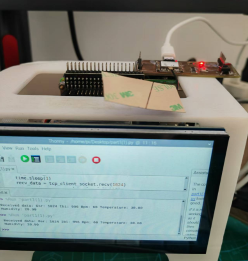
A result picture.

Modify the code to send real DHT-11 data
The modified code for XIAO ESP32 is below:
#include <Arduino.h>
#include <WiFi.h>
#include "DHT.h"

// Wi-Fi Server setup
WiFiServer server(1122);

// DHT-11 configuration
#define DHTPIN A2       // Pin connected to DHT-11
#define DHTTYPE DHT11   // Define the type of DHT sensor (DHT-11)
DHT dht(DHTPIN, DHTTYPE);

// Variables to store sensor data
float temperature = 0.0;
float humidity = 0.0;

// Strings for data transmission
char temperature_str[10];
char humidity_str[10];

// Initialize Wi-Fi SoftAP
void Wifi_TCP_Init() {
  WiFi.softAP("ESP32-DHT"); // Access Point name
  server.begin();           // Start server
  Serial.begin(115200);     // Initialize serial communication
  Serial.println("WiFi server started!");
}

// Read DHT-11 sensor data
void readDHTData() {
  humidity = dht.readHumidity();       // Read humidity
  temperature = dht.readTemperature(); // Read temperature in Celsius

  // Check for failed readings
  if (isnan(humidity) || isnan(temperature)) {
    Serial.println("Failed to read from DHT sensor!");
    return;
  }

  // Convert sensor data to strings
  dtostrf(temperature, 5, 2, temperature_str);
  dtostrf(humidity, 5, 2, humidity_str);
}

// Continuously send data over TCP
void Wifi_TCP_Send() {
  WiFiClient client = server.available(); // Check if a client is connected
  if (client) {
    Serial.println("Client connected!");

    while (client.connected()) { // Keep sending data while the client is connected
      readDHTData(); // Read the latest sensor data

      // Send temperature and humidity data
      client.print('T');
      client.print(temperature_str);
      client.print('H');
      client.print(humidity_str);
      client.print("\n"); // Add newline for easy parsing
      delay(100);

      Serial.println("Data sent to client:");
      Serial.print("Temperature: "); Serial.println(temperature_str);
      Serial.print("Humidity: "); Serial.println(humidity_str);

      delay(1000); // Send data every second
    }

    Serial.println("Client disconnected.");
    client.stop(); // Stop the client when it disconnects
  }
}

void setup() {
  dht.begin();          // Initialize the DHT-11 sensor
  Wifi_TCP_Init();      // Initialize Wi-Fi and server
}

void loop() {
  Wifi_TCP_Send();      // Continuously send sensor data over Wi-Fi
}
The modified code for Raspberry Pi is below:
import socket

if __name__ == "__main__":
    tcp_client_socket = socket.socket(socket.AF_INET, socket.SOCK_STREAM)
    tcp_client_socket.connect(("192.168.4.1", 1122))  # Connect to ESP32 server
    print("Connected to ESP32 server")

    buffer = ""  # Initialize buffer to store incoming data

    try:
        while True:
            # Receive data and append it to the buffer
            recv_data = tcp_client_socket.recv(1024).decode("utf-8")
            buffer += recv_data

            # Debug: Print raw received data
            # print(f"Raw Data: {buffer}")

            # Process complete messages ending with '\n'
            while '\n' in buffer:
                message_end = buffer.index('\n')  # Find the end of the first complete message
                message = buffer[:message_end]   # Extract the complete message
                buffer = buffer[message_end + 1:]  # Remove the processed message from the buffer

                # Parse the message
                if 'T' in message and 'H' in message:
                    try:
                        temperature_start = message.index('T') + 1
                        humidity_start = message.index('H') + 1

                        # Extract temperature and humidity
                        temperature = message[temperature_start:humidity_start - 1].strip()
                        humidity = message[humidity_start:].strip()

                        print(f"Temperature: {temperature}°C, Humidity: {humidity}%")
                    except Exception as e:
                        print(f"Parsing Error: {e}")
                else:
                    print(f"Invalid message format: {message}")
    except KeyboardInterrupt:
        print("Exiting...")
    finally:
        tcp_client_socket.close()
See final result video: