Appearance
Mechanical Design & Machine Making 2023
I am the only student at our node. Therefore, I independently completed the group assignment by myself. The content of this assignment has already passed the review of the Asia-Pacific region.
During these two weeks of design and making assignment, I have tried to realize the mechanical functions of my dog feed machine. This assignment covered all the necessary content for the mechanical design and mechanical manufacturing project sections.
Motivation
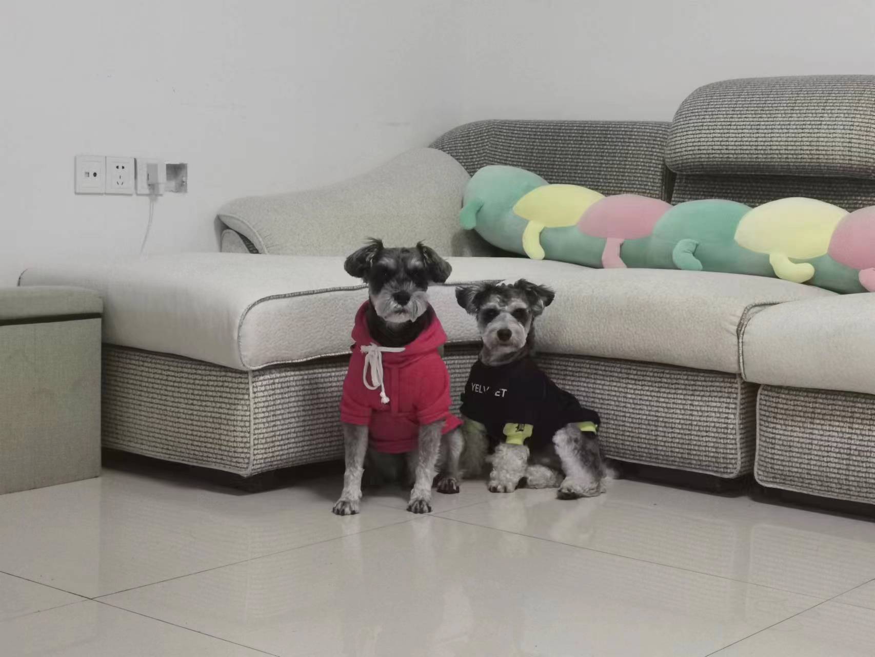
I have two puppies in my house, but I often miss feeding them on time because I'm busy. Therefore I plan to build a remote-controlled auto-dog-feeder.
Idea Sketch
The picture below shows the original design concepts of my dog feed machine.
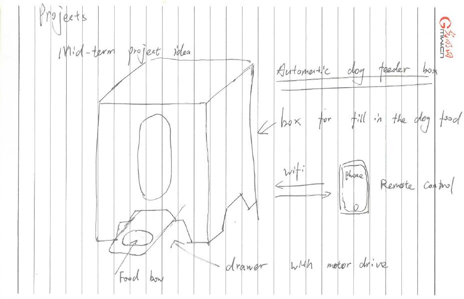
This dog feeder consists of 4 parts:
- A box containing the dog food.
- A drawer drove by a simple motor.
- A control board with WiFi access.
- A user interface on phone for remote control.
After weeks of learning I have adjusted my design concepts and the picture below demonstrated the overall design concepts of my dog feed machine.
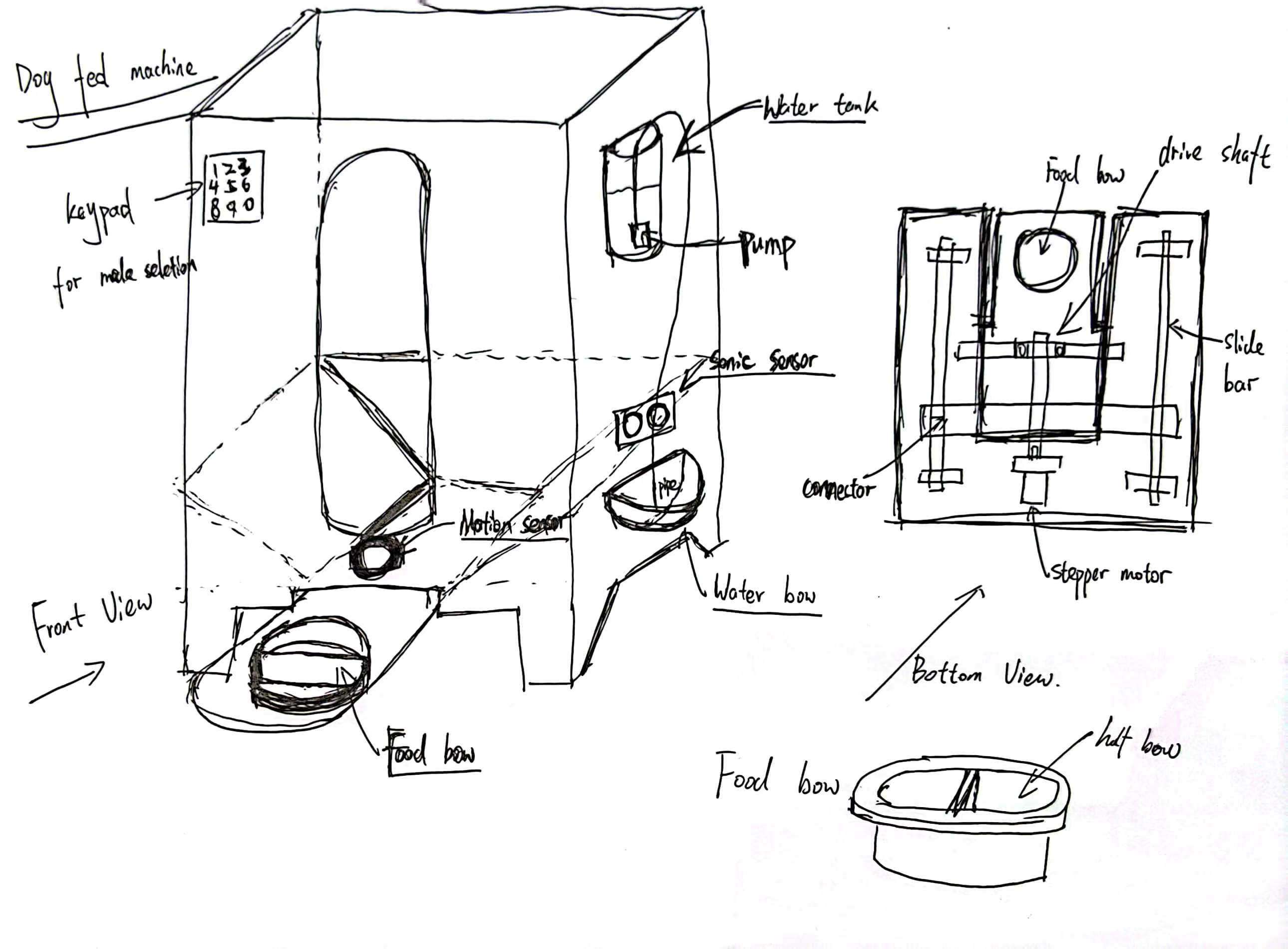
At this stage I have planed to realize the following two functions:
- A motion sensor/ultrasonic sensor was used to control the feeding process, once the dog is moving around the feeder gate then the motor will push out the food bow for dog to eat.
- Add a keypad or button input module to select how much food would be feed to the dog.(Half Bow by sending out half of the food bow or Full Bow by sending out the entire food bow.)
Structure Construction
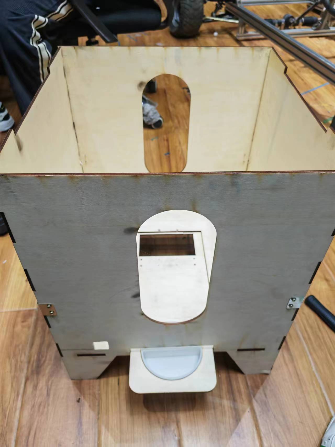
Structural design, cutting and assemble of the feeder box was done in week 2 and 3.

Mechanical Design
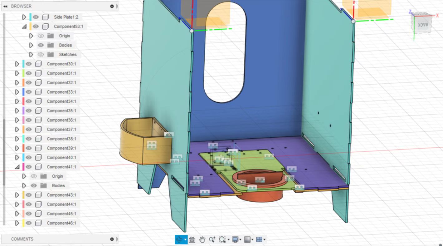
The following picture show the 1st version mechanical design.
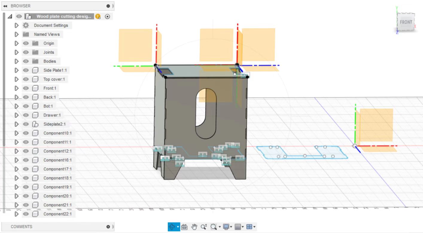
In this design the motor was placed at right
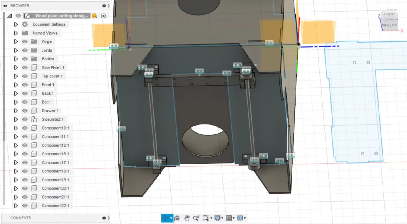
Unfortunately, this structure will easily get stuck as the driving force act on only one side.
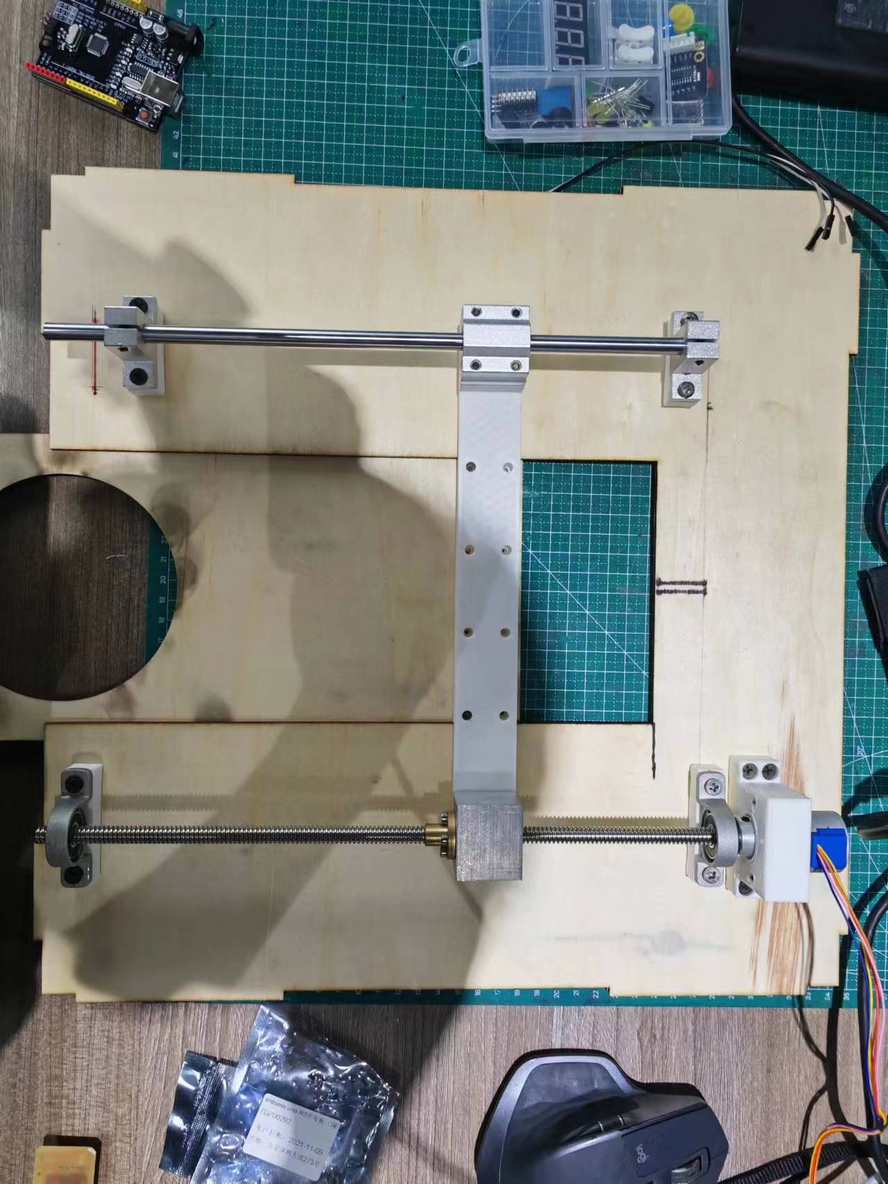
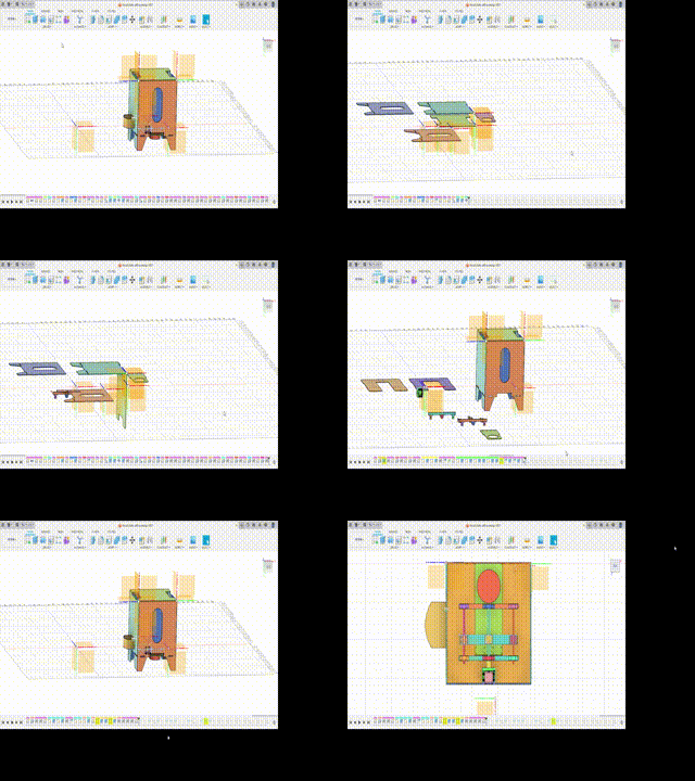
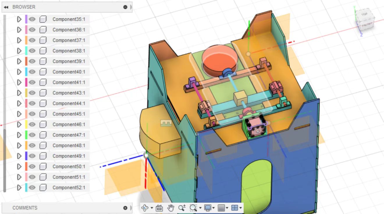
Therefor the 2nd version was created as follow, the structure was redesigned and the motor was put at the center.
Electronics Design
At first I planed to use the board produced in output device week (using XIAO as MCU) to drive a 28 motor to push food to my dog however the torque it generates is not enough.
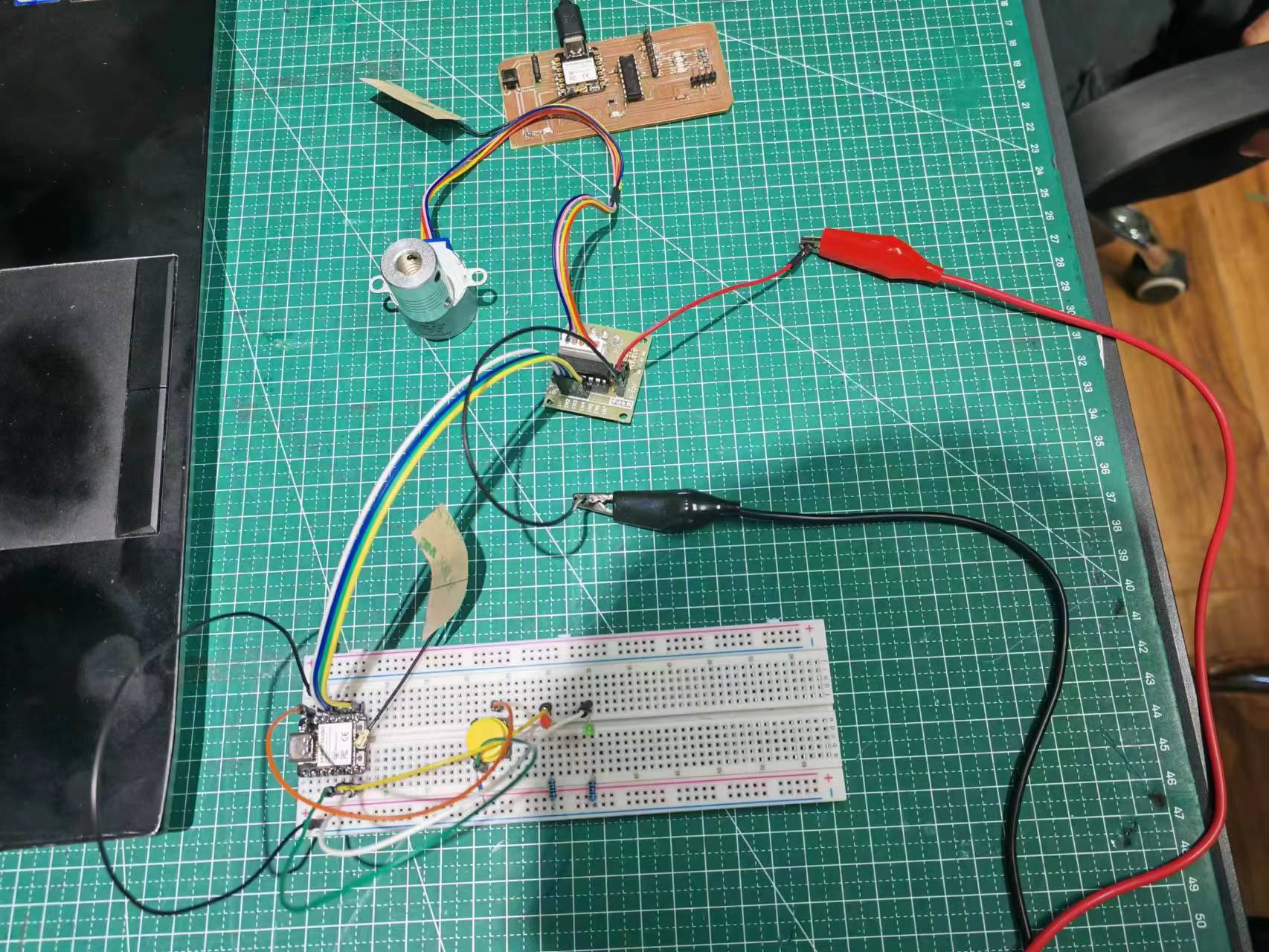
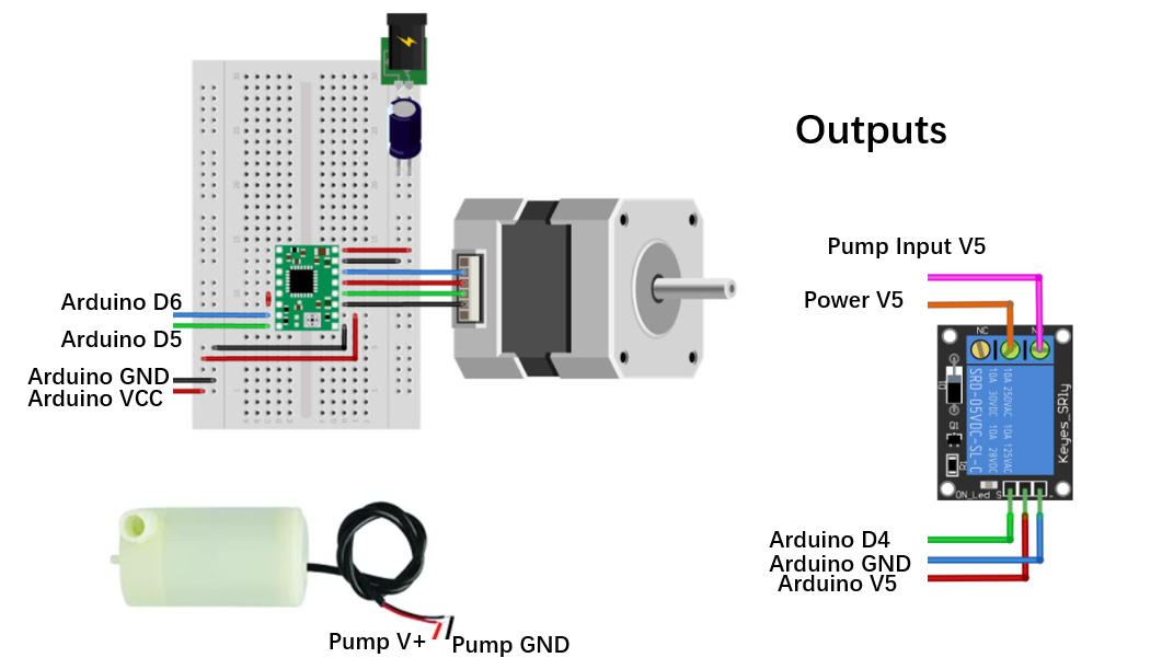
Therefore the circuit system was redesigned and current electronic elements used in this machine design include:
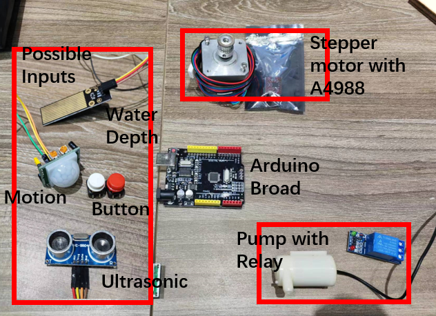
- An arduino control board.
- A stepper motor with A4988 controller.
- A ultrasonic sensor for detecting the dogs approching water bow.
- A motion sensor for detecting the dogs are moving around the food gate.
- A water pump control by a relay.
- A keypad or button for fed mode selection (full bow or half bow).
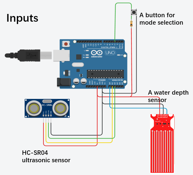
The electronic inputs are connected as follow.
The electronics outputs are connected as follow.
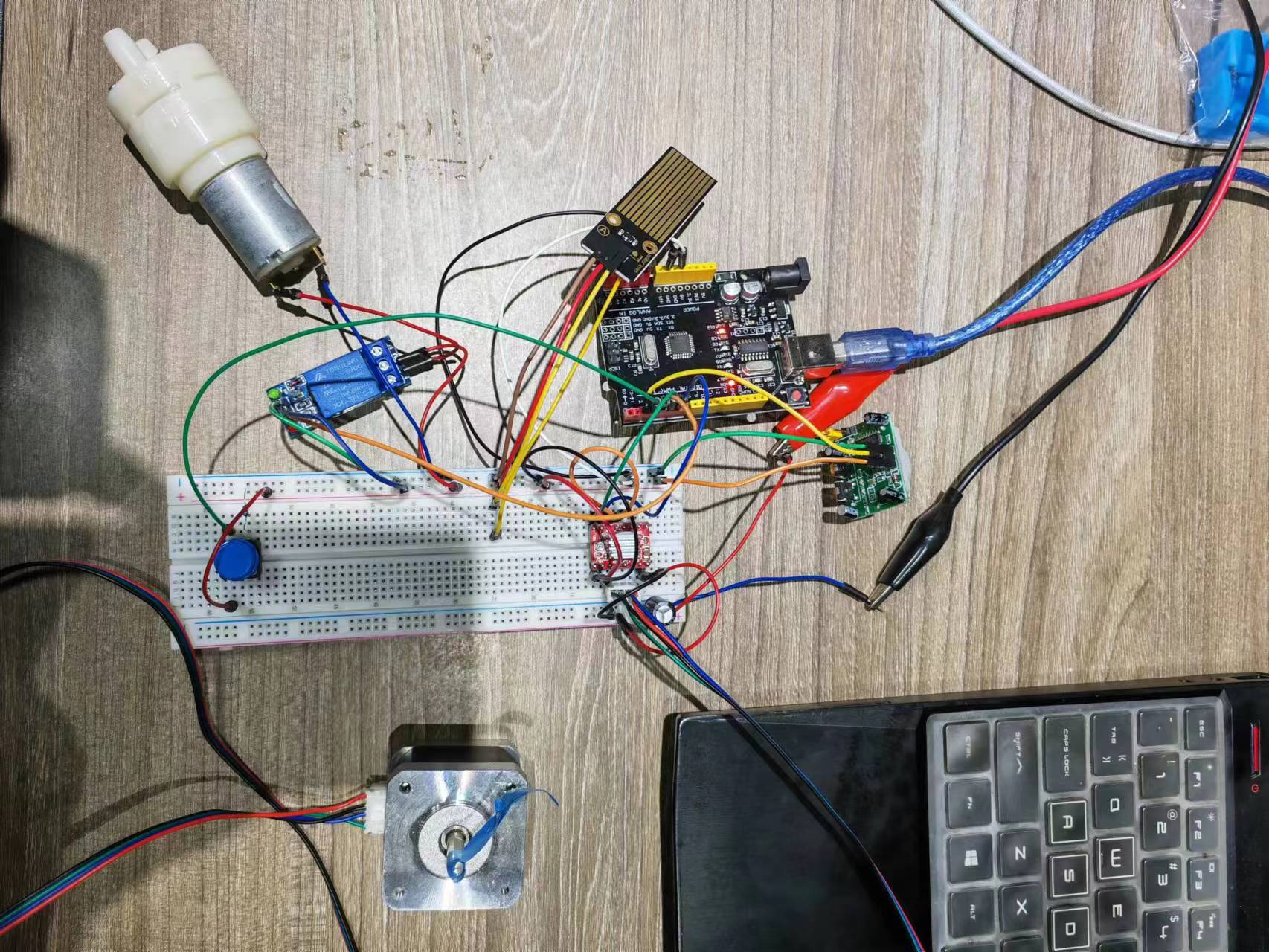
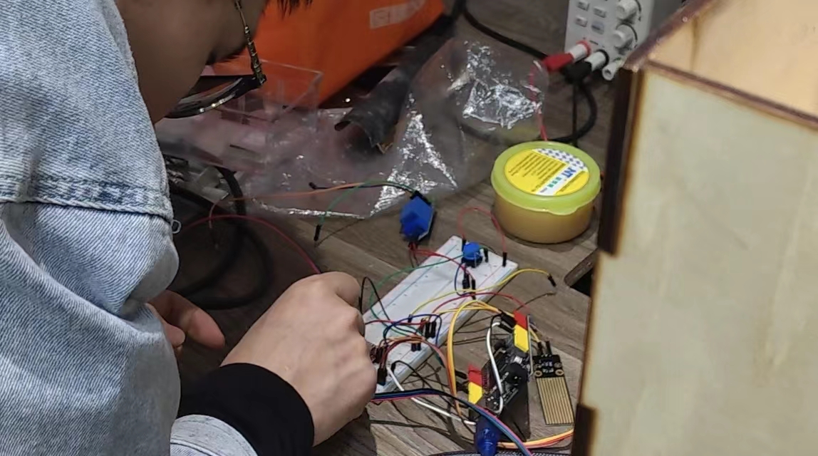
Connecting everyting on a bread board.
Coding
This code works with ultrasonic sensor control the motor to feed the dog when dog is approching the food gate. The feed mode (full bow / half bow) can be selected using a button.
#define EchoPin A1
#define TrigPin A0
// Define pin connections & motor's steps per revolution

const int buttonPin = 12;
const int dirPin = 5;
const int stepPin = 6;
const int stepsPerRevolution = 200;
int motion;
int count = 0;
int buttonState = 0;   // variable for reading the pushbutton status
int buttonCount = 0;
long duration;

void setup()
{
	// Declare pins as Outputs
  Serial.begin(9600);
  pinMode(TrigPin, OUTPUT);
  pinMode(EchoPin, INPUT);
	pinMode(stepPin, OUTPUT);
	pinMode(dirPin, OUTPUT);
  pinMode(buttonPin, INPUT);
  digitalWrite(TrigPin, LOW);
}

void loop()
{
  int modeVal = getMode();
  Serial.println("Mode type");
  Serial.println(modeVal);
  if(modeVal == 1){
     Serial.println("Sensor loop count");
     Serial.println(count++);
     Serial.println(getDistance());

     motion = getDistance();
     if(motion < 100){
       Serial.println("Dog coming! Gate open!");
       // Set motor direction clockwise
       digitalWrite(dirPin, LOW);
      // Spin motor slowly
   	  for(int x = 0; x < 75*stepsPerRevolution; x++)
   	  {
   	  	digitalWrite(stepPin, HIGH);
   	  	delayMicroseconds(1000);
   	  	digitalWrite(stepPin, LOW);
   	  	delayMicroseconds(1000);
   	  }
   	  delay(3000); // Wait a second
   	  // Set motor direction counterclockwise
   	  digitalWrite(dirPin, HIGH);
   	  // Spin motor quickly
   	  for(int x = 0; x < 75*stepsPerRevolution; x++)
   	  {
   	  	digitalWrite(stepPin, HIGH);
   	  	delayMicroseconds(1000);
   	  	digitalWrite(stepPin, LOW);
   		  delayMicroseconds(1000);
   	  }
     } else {
       Serial.println("No dog!");
      }
     Serial.println("");
     delay(5000);
  }

  else if (modeVal == 0){
     Serial.println("Sensor count");
     Serial.println(count++);
     Serial.println(getDistance());

     motion = getDistance();
     if(motion <100){
       Serial.println("Dog coming! Gate open!");
       // Set motor direction clockwise
       digitalWrite(dirPin, LOW);
      // Spin motor slowly
   	  for(int x = 0; x < 50*stepsPerRevolution; x++)
   	  {
   	  	digitalWrite(stepPin, HIGH);
   	  	delayMicroseconds(1000);
   	  	digitalWrite(stepPin, LOW);
   	  	delayMicroseconds(1000);
   	  }
   	  delay(3000); // Wait a second
   	  // Set motor direction counterclockwise
   	  digitalWrite(dirPin, HIGH);
   	  // Spin motor quickly
   	  for(int x = 0; x < 50*stepsPerRevolution; x++)
   	  {
   	  	digitalWrite(stepPin, HIGH);
   	  	delayMicroseconds(1000);
   	  	digitalWrite(stepPin, LOW);
   		  delayMicroseconds(1000);
   	  }
       delay(5000);
     } else {
       Serial.println("No Dog");
       delay(5000);
      }
      Serial.println("");
  }

}


int getMode(){
  buttonState = digitalRead(12);
  if (buttonState == 1){
    buttonCount++;
  } else {
    buttonCount=buttonCount + 0;
  }
  return buttonCount % 2;
}


long getDistance() {
    // trig
    digitalWrite(TrigPin, LOW);
    delayMicroseconds(2);
    digitalWrite(TrigPin, HIGH);
    delayMicroseconds(10);
    digitalWrite(TrigPin, LOW);
    // echo
    duration = pulseIn(EchoPin, HIGH);     // unit: us
    return duration * 0.34029 / 2;         // unit: mm
}
Machine Making
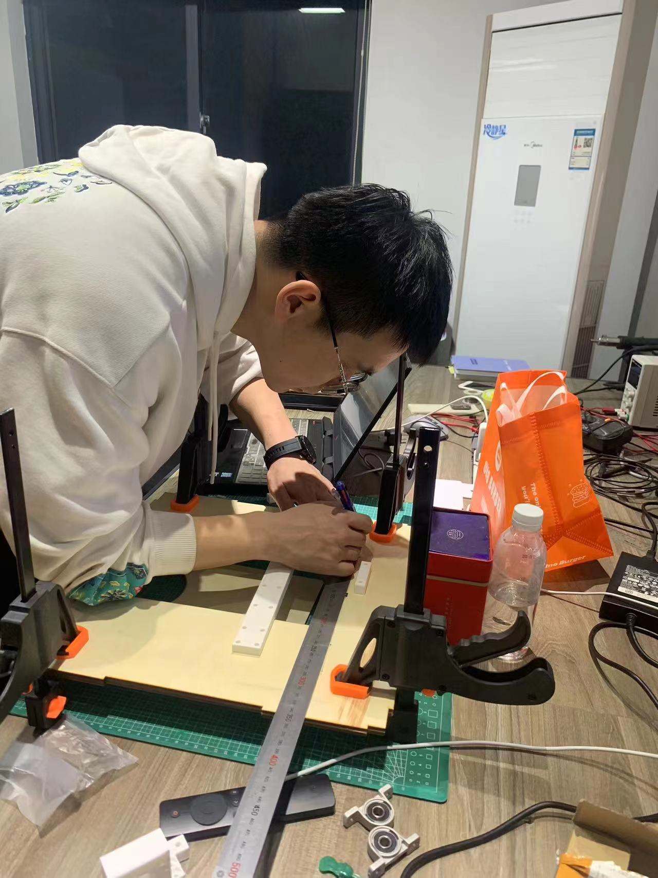
Assemble the motor driving structure.
Final Video
Control the motor with ultrasonic sensor, other inputs and output device such as motion-sensor/water-pump were also tested.
Lessons learned
Learn form mistakes.
- Mechanical design issues: Think if it works with load.
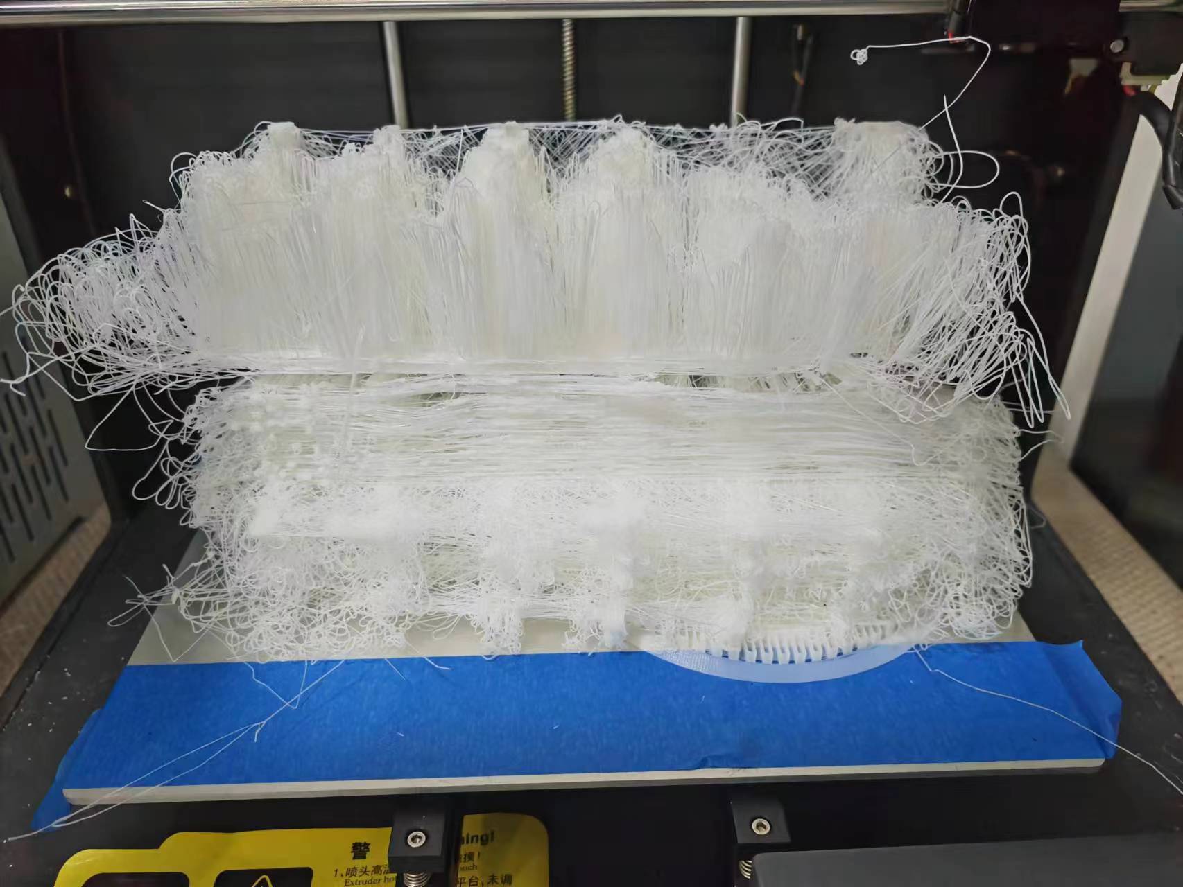
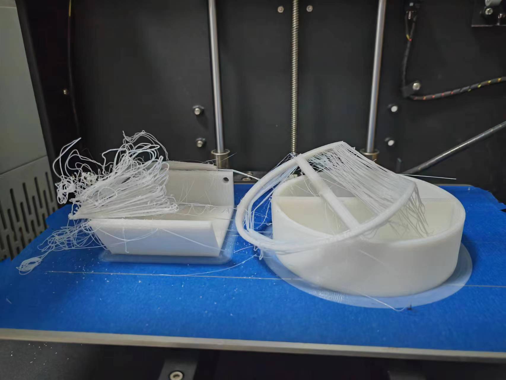
- 3D Printing issues:Leave time for test printing.
- MCU selection issues: Notice number of pins used.
- Board production: Soldering issues.
- Electronics design:Consider power supply, how much voltage will be going through the board.
Reference
All 3D designs were accomplished using Fusion 360 and details can be download via link : https://a360.co/3MZzOEG (please be aware that all structural parts were produced with laser-cut and bearing/motor supporting parts were 3D printed.)