Week 6. Electronic Design
Image Courtesy: Photo by Adi Goldstein on Unsplash
In this assignment, we will explore the fundamental concepts of electronic design, including circuits, components, and the principles of electronic engineering. Here we will learn how to design and build circuits.
Assignment Tasks:
- Group Assignment: Observe how a microcontroller circuit board operations using the test equipment in your lab.
- Individual Assignment: Design a development board with an embedded microcontroller to interact and communicate with it. Try out various workflows, develop a case for them, and, if possible, simulate their operation.
Learning Process
Circuit
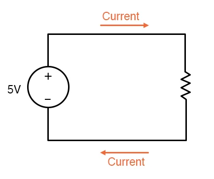
A circuit is a closed path that consists of circuit components in which electrons from a voltage or current source can flow. If the circuit consists of electric components like a resistor, a capacitor, an inductor etc. then it will be called an Electrical circuit. The simplest circuit is a battery and a resistor, as shown below. Without the resistor, the battery would short circuit, causing all of the electrons to flow from one end to the other and draining the battery.
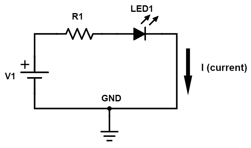
If the circuit consists of any of the electronic circuit components like a diode, a Transistor etc. then it will be called an Electronic circuit. So, the electronic circuits may consist both of the electrical and electronic circuit components, but an electrical circuit will have only the electrical components. Basic electronic circuit with a battery source, resistor, and LED is shown below. Given that we have an LED, the system can be regarded as an electrical circuit.
Circuits can be classified into two broad categories: analog circuits and digital circuits. Analog circuits process continuous signals, while digital circuits process signals that are discrete and binary in nature.
Analog circuits are circuits that process signals that are continuous and vary in magnitude and direction over time. Examples of analog signals include audio signals, voltage signals from sensors, and signals from physical sensors such as temperature sensors, pressure sensors, and light sensors. Analog circuits use analog components such as resistors, capacitors, inductors, amplifiers, and filters to manipulate these signals. Analog circuits can be further classified into linear and nonlinear circuits, depending on the relationship between the input and output signals.
Digital circuits, on the other hand, are circuits that process signals that are discrete and binary in nature, taking on only two values: high or low, 1 or 0. Examples of digital signals include the output of a switch or button, signals from a digital sensor such as a motion sensor, and data signals in digital communication systems. Digital circuits use digital components such as logic gates, flip-flops, registers, and microprocessors to manipulate these signals. Digital circuits can be further classified into combinational and sequential circuits, depending on the way the input signals are processed.
Understanding Basic Components
Power Source
A power source in a circuit provides electrical energy to the components of the circuit. Power sources can take many forms, including batteries, generators, power supplies, and solar cells. A USB connection to a laptop, a power socket through an adapter & USB can also be considered a power source.
Resistor
A resistor is an electrical component that opposes the flow of electrical current in a circuit. It is designed to reduce the voltage and current levels in a circuit, and to control the amount of electrical energy that is dissipated as heat. Resistors follow Ohm’s law which states that the resistance is the voltage divided by the current: R = V / I. Using the formula for power we can also write the equation for power as P = V * I = R * I^2.

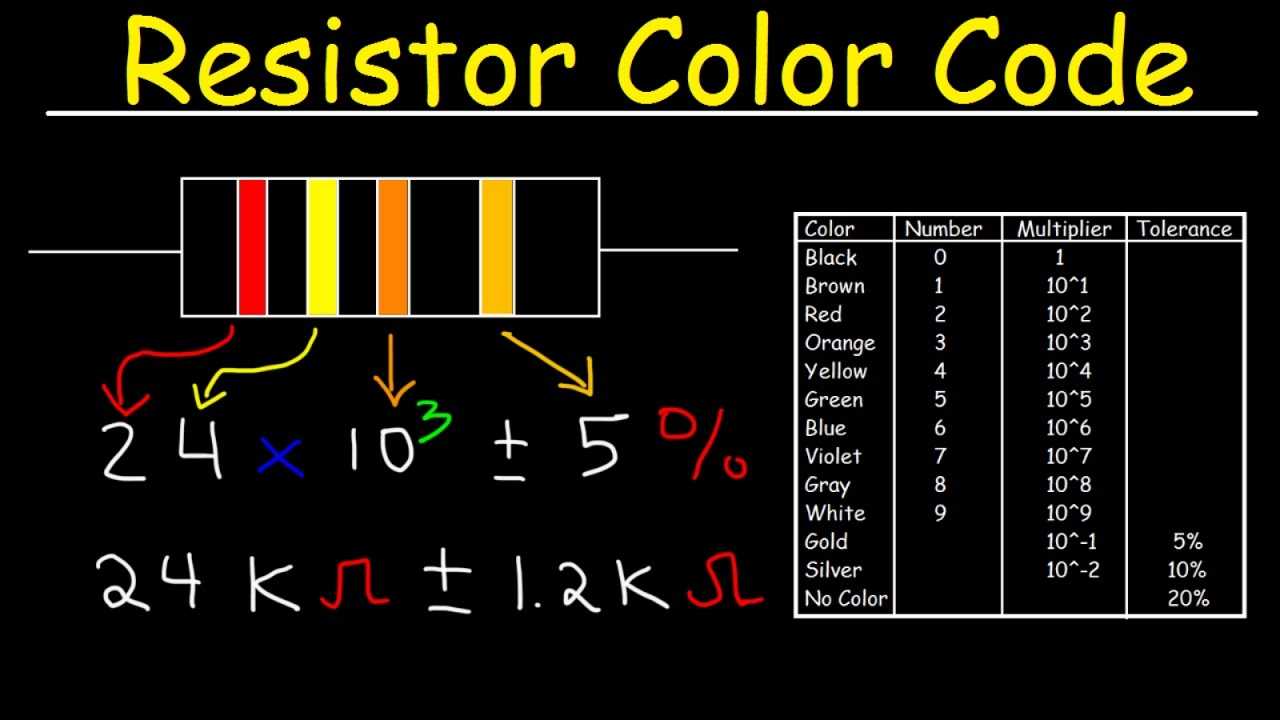
Colour Code for Resistor.
Resistor color codes are used to represent the value of a resistor by a series of colored bands printed on the body of the resistor. The number and color of bands on the resistor indicate the resistance value, tolerance, and sometimes the temperature coefficient of the resistor.
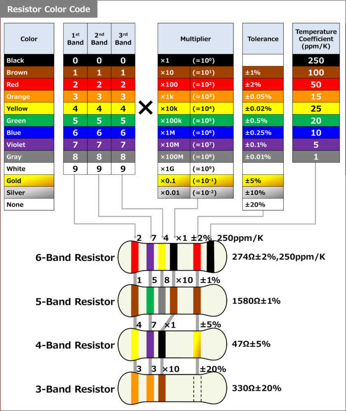
The colour code mainly divided into 3 parts:
-
Resistance Value: First two/ three bands depends on which band type resistor. Each color corresponds to a specific digit, as shown in the table.
-
Multiplier: Fourth line for 5 & 6 Band resistors or thrid line for 3 & 4 Band resistors. Multiplier that must applied to the first two/three digits to obtain the resistance value. Each color corresponds to a specific multiplier, as shown in the table.
-
Tolerance Value: The tolerance band is usually the last band on the resistor and indicates the allowable variation in the resistance value. The tolerance band can be identified by its color code, which is usually silver or gold. If there is no tolerance band, the resistor has a tolerance of 20%.
-
Temperature coefficient band (optional): Some resistors have a temperature coefficient band that indicates how the resistance value changes with temperature. The temperature coefficient band can be identified by its color code, which is usually brown.
Capacitor
A capacitor is an electrical component that stores electrical charge and energy in an electric field. It is composed of two conductive plates separated by a dielectric material. Capacitors are used in a wide range of applications, such as smoothing voltage spikes in power supplies, storing energy in electronic circuits, and filtering signals in audio circuits.
A capacitor is required in all electronic circuits because even minor fluctuations in power can result in incorrect results. The capacitor acts as a voltage regulator in the circuit. Therefore, it’s crucial to find the ideal capacitor.

LEDs and Diodes
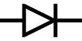
A diode is a semiconductor device that essentially acts as a one-way switch for current. It consists of a p-type and an n-type semiconductor material, which are joined together to form a p-n junction. When a voltage is applied to the diode in the forward direction, it allows current to flow, while in the reverse direction, it blocks the current flow. Diodes are commonly used in rectifiers, voltage regulators, and signal processing circuits.
The diode which emits light during the conduction is known as the light emitting diode or LED. It works on the phenomenon of the electro-luminance in which the semiconductor material emits light when placed under the influence of the electric field. LEDs are commonly used in lighting applications, such as traffic lights, displays, and automotive lighting. They are also used in electronic circuits as indicators and in optical communications.
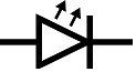
LED has a specific polarity that must be applied to make it produce light. Failure to observe this polarity requirement could cause catastrophic damage to the LED. This is because an LED has a relatively low value of reverse polarity voltage that is allowed (normally about 5 volts). Since an LED is essentially a diode, it has a maximum current value that cannot be exceeded for any period of time. Thus a resistor is added across the circuit to protect the LED. For calculating the esistor value for LEDs, these following steps need to be considered:
-
Determine the voltage and current needed for your LED.
-
We’ll use the following formula to determine the resistor value: Resistor = (Battery Voltage – LED voltage) / desired LED current.
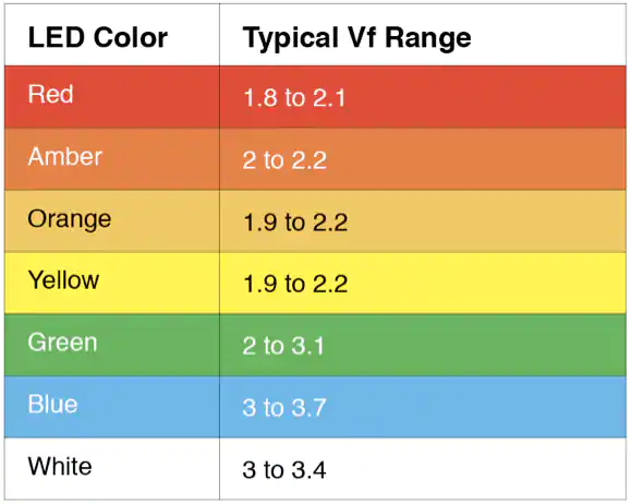
Finding this, the voltage of LEDs plays a significant role in figuring out the resistor value, and the voltage for LEDs varies depending on their colour. The table below shows the voltage range for various colour LEDs.
Microcontrollers
A microcontroller is a small computer on a single integrated circuit (IC) that is designed to control a specific system or device. It is a specialized computing device that is designed to control a specific system or device. It typically includes a processor, a small amount of memory, and input/output peripherals such as timers, serial communication interfaces, and analog-to-digital converters, all of which are integrated onto a single chip. Microcontrollers are typically programmed to perform specific tasks, and run specialized software known as firmware.
Microcontrollers are used in a wide range of electronic devices, including smartphones, automotive systems, home appliances,industrial automation equipment, and more. They are also commonly used in embedded systems, which are computer systems that are integrated into other devices or products to provide specific functionality.
One of the key benefits of using microcontrollers is that they can be programmed to perform specific tasks, which can greatly enhance the functionality of a device. They are also cost-effective, consume less power than traditional computers, and can be easily integrated into electronic systems.
During this week we’ll be working with the ATtiny 412.
ATtiny412 is a microcontroller from the Atmel AVR family of microcontrollers. It is a low-power, high-performance 8-bit microcontroller that is designed for a wide range of applications, including industrial, commercial, and consumer products. The Data Sheet of each microcontroller contains information about its functions and performance, so it is essential that you comprehend this information.
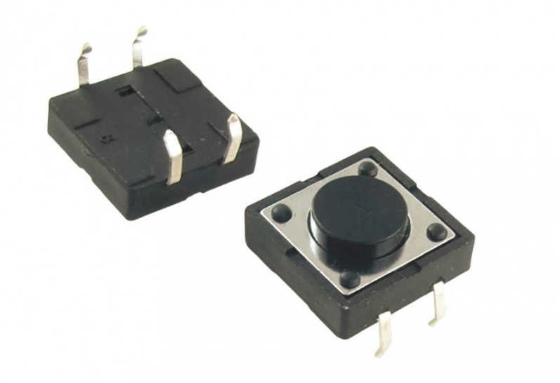
Switches/Buttons
Switches and buttons are commonly used in electronic circuits to control the flow of current or to trigger specific functions. They are essentially devices that make or break an electrical connection.
Switches come in different types, such as toggle switches, rocker switches, and slide switches. They are typically used to turn a circuit on or off, or to change the state of a circuit. When the switch is in the ON position, it allows current to flow through the circuit, while in the OFF position, it stops the flow of current.
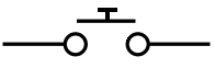
Buttons, on the other hand, are momentary switches that are typically used for functions such as resetting a circuit or triggering an action. They work by temporarily closing an electrical connection when they are pressed, and opening the connection when they are released.
UPDI
UPDI (Unified Program and Debug Interface) is a communication interface that is used to program and debug microcontrollers produced by Atmel (now part of Microchip Technology). UPDI is a two-wire interface that is used to communicate between a programming device (such as a debugger or programmer) and a microcontroller.
Design a Circuit Board
Electrical circuit design is the process of creating an electronic circuit that can perform a specific function or set of functions. The design process involves selecting and integrating electronic components, such as resistors, capacitors, transistors, and integrated circuits, in a way that meets the electrical and performance requirements of the desired application.
A circuit can be designed using a variety of EDA softwares. The following are a few of the most significant:
-
KiCAD
-
Eagle PCB Designer (Now Intergrated with Fusion 360)
EDA
EDA stands for Electronic Design Automation. It is a term used to describe a set of software tools used by electronic engineers to design, simulate, analyze, and test electronic circuits and systems. EDA tools automate many of the design tasks and enable engineers to create complex electronic designs quickly and efficiently.
EDA tools are used throughout the electronic design process, from the initial concept stage through to manufacturing and testing. Some of the key features of EDA tools include:
-
Schematic Capture: Allows engineers to create a graphical representation of the electronic circuit.
-
PCB Layout: Enables engineers to place components on a printed circuit board and create routing connections between them.
-
Simulation: Allows engineers to test the behavior of the electronic circuit under different conditions, such as temperature, voltage, and noise.
-
Analysis: Enables engineers to analyze the performance of the electronic circuit, such as its power consumption, signal integrity, and thermal behavior.
-
Testing: Allows engineers to test the electronic circuit in a real-world environment to ensure it meets its design specifications.
Individual Assignment - “Making a Hello World Board”
The task for the assignment is to build a “Hello World Board” using an ATtiny412 board and to add a switch and an LED (2nos LED Optional). Our tutor explained the schematic, and we recreated it in KiCAD.
I was a little uneasy when I sat in front of our tutor as he explained the theory behind this because I was new to electronics. I then decided to research this topic a little more and found some interesting documents created by our previous students that helped greatly in my understanding. When I searched for ATtiny412, I came across a schematic that I initially didn’t understand. I then dug deeper, and eventually, with the assistance of my fellow students and our tutor, I was able to further understand the schematic. Throughout our conversation, I set this schematic aside and began referencing it along with theories.
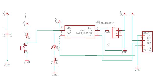
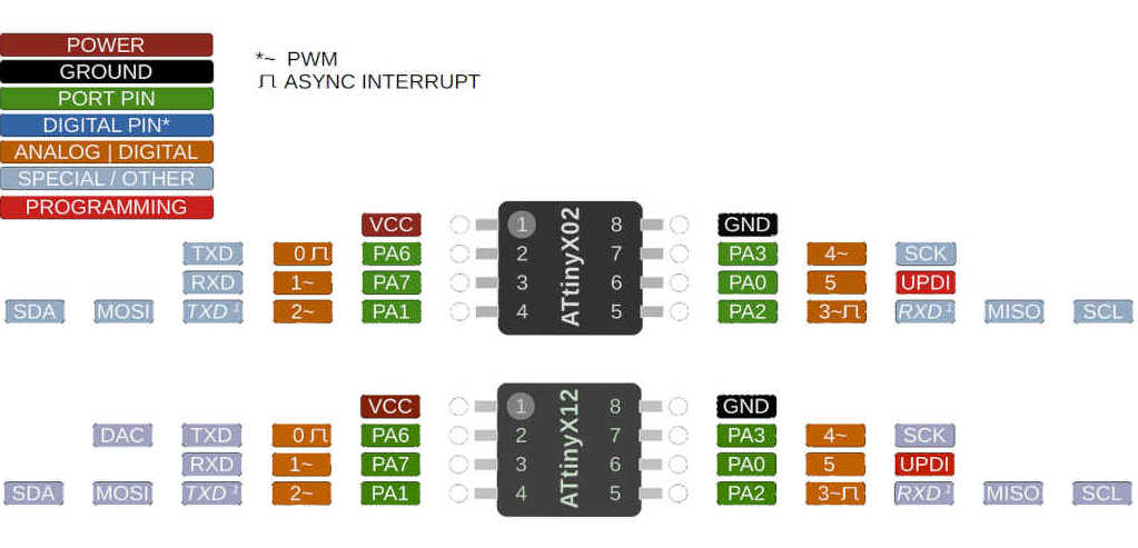
I finally realised that this was cracked using reverse engineering. I began with the pinout of an ATtiny 412.
Understanding the pinout for ATtiny 412 in detail:
| Term | Meaning |
|---|---|
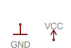
| VCC | Power supply |
| GND | Ground |
| PA | The name for digital pins, which all of these pins are |
| PWM | Pulse Width Modulation |
| TXD | Transmit Data, which is a signal line used to transmit data from one device to another in a serial communication protocol such as UART (Universal Asynchronous Receiver-Transmitter) |
| RXD | Receive Data, which is a signal line used to receive data from another device in a serial communication protocol such as UART (Universal Asynchronous Receiver-Transmitter) |
| MOSI | Master Output Slave Input. It is a signal line used in a serial communication protocol such as SPI (Serial Peripheral Interface) to transmit data from the master device to the slave device |
| MISO | Master Input Slave Output. It is a signal line used in a serial communication protocol such as SPI (Serial Peripheral Interface) to receive data from the slave device to the master device |
| SDA | Serial Data Address, which is a signal line used in the I2C (Inter-Integrated Circuit) communication protocol to transmit data between the master and the slave devices |
| SCK | Serial Clock, which is a signal line used in various serial communication protocols such as SPI (Serial Peripheral Interface) and I2C (Inter-Integrated Circuit) to synchronize the data transmission between the master and the slave devices |
| SCL | Serial Clock, which is a signal line used in the I2C (Inter-Integrated Circuit) communication protocol to transmit clock signals from the master device to the slave device |
In our case we are using ports for the following functions:
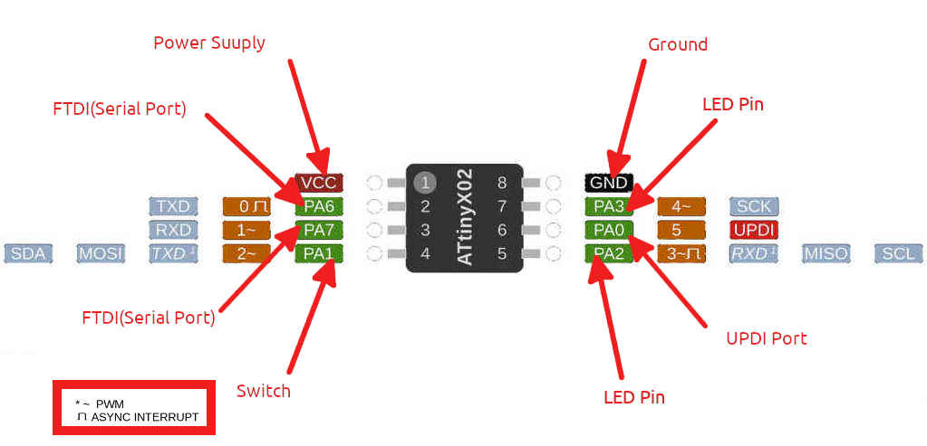
It’s time to install our EDA software and start designing a stunning circuit. KiCAD will be used as our starting point.
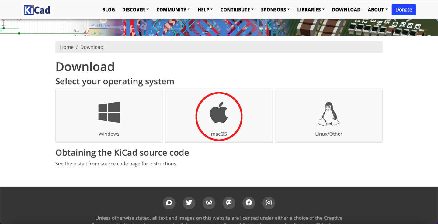
KiCAD
KiCAD is an open-source software tool for electronic design automation (EDA) that provides schematic capture, PCB layout, and 3D visualization capabilities. Download KiCAD and install it. Since I was using Macbook, I downloaded KiCAD for macOS and installed.
Introduction to KiCAD
KiCAD is used to create schematics, printed circuit board layouts, and 3D models for electronic components. KiCAD offers a user-friendly interface that is intuitive to use and is suitable for both beginners and advanced users. The software suite includes a wide range of features such as schematic capture, footprint editor, 3D viewer, and automatic routing tools. KiCAD also supports a variety of file formats, making it compatible with other EDA software and allows for easy collaboration with other designers. Additionally, KiCAD is free to use and is constantly being updated and improved by a community of developers, making it a popular choice for hobbyists and professional designers alike.
It comes with a global library of components that is very useful to use, and we can add our own libraries and use it based on our inventory. We use the Fab Lab’s own library because the components are readily available here anyway. Since we follow Fablab inventory, it is always good to follow Fablab library.
Getting Started
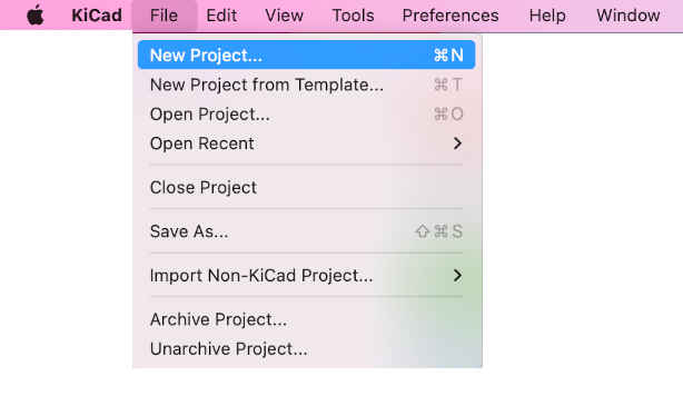
Open Kicad, Go to File - > New Project.
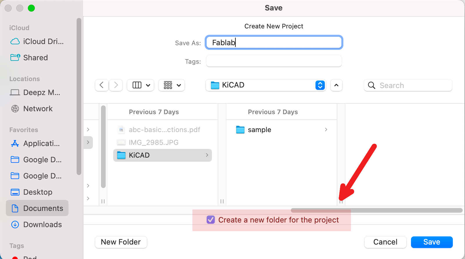
Please make sure a new folder is created when creating a new project. Because unlike other CAD software, a lot of files will be created here for a new project. Which we will discuss later.
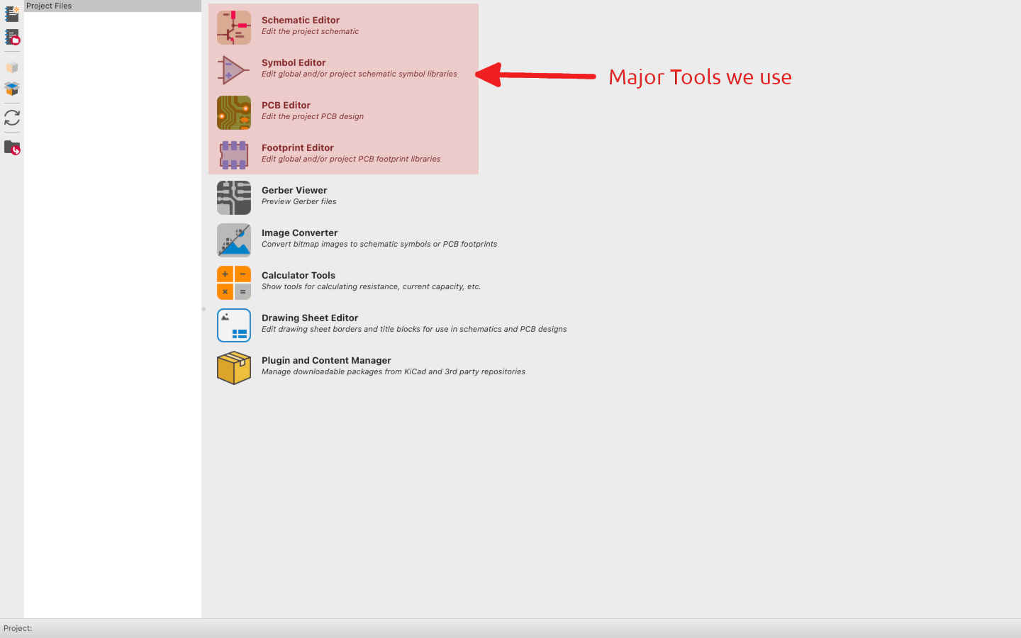
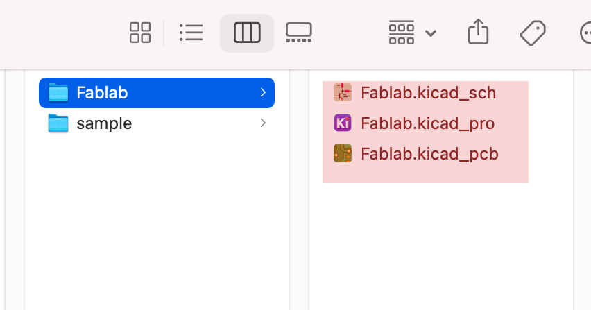
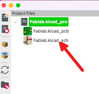
Once a New Project is created, it automatically creates 3 different files, one for schematic, second file is the master file and third file is for PCB
After this, double click the schematic file to start design.
Understanding the Window.

Create new components from create new symbols. This will direct you to the library.

Search for required components in the library. and add the same to schematic.
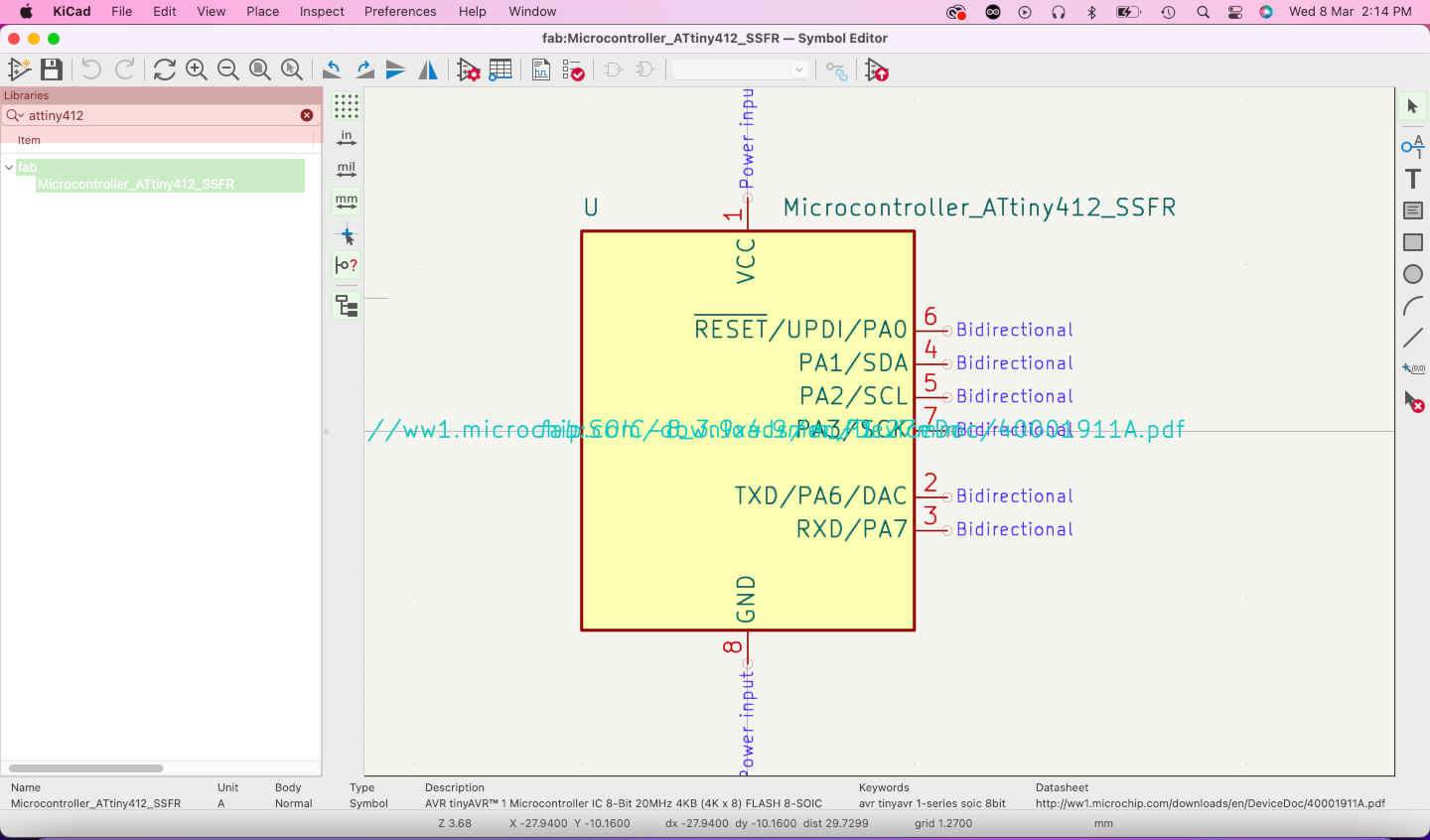
Add the same to schematic.

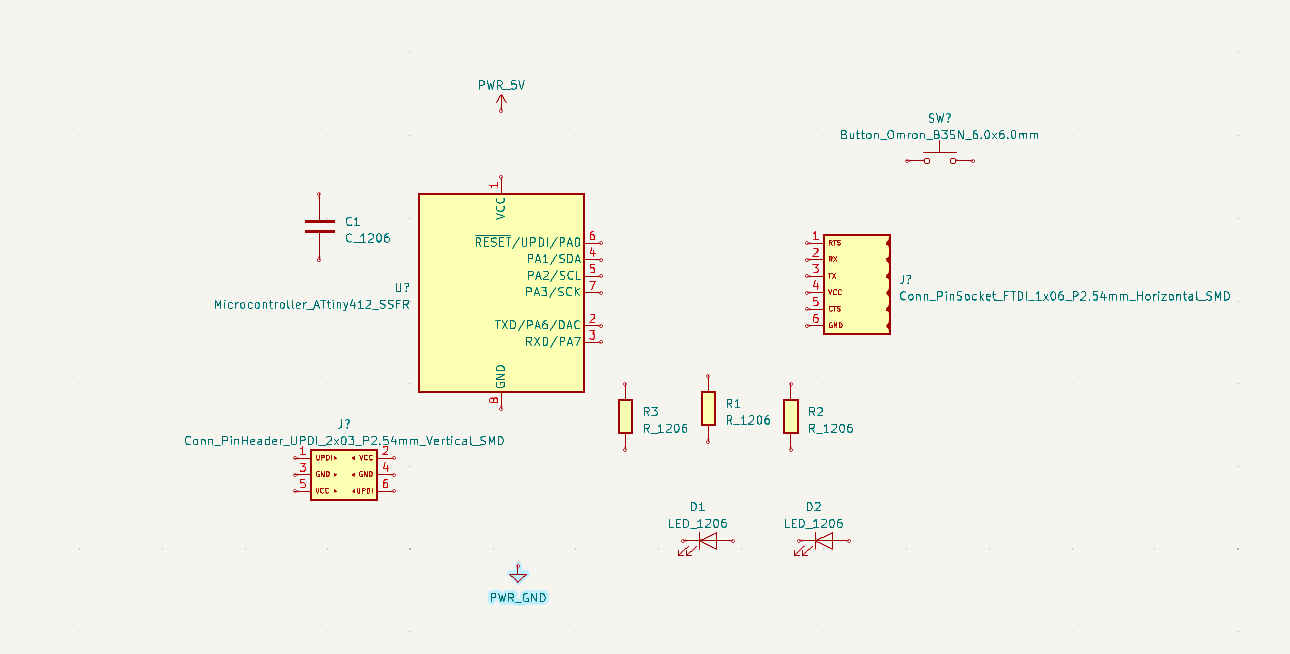
I placed all the required components first.
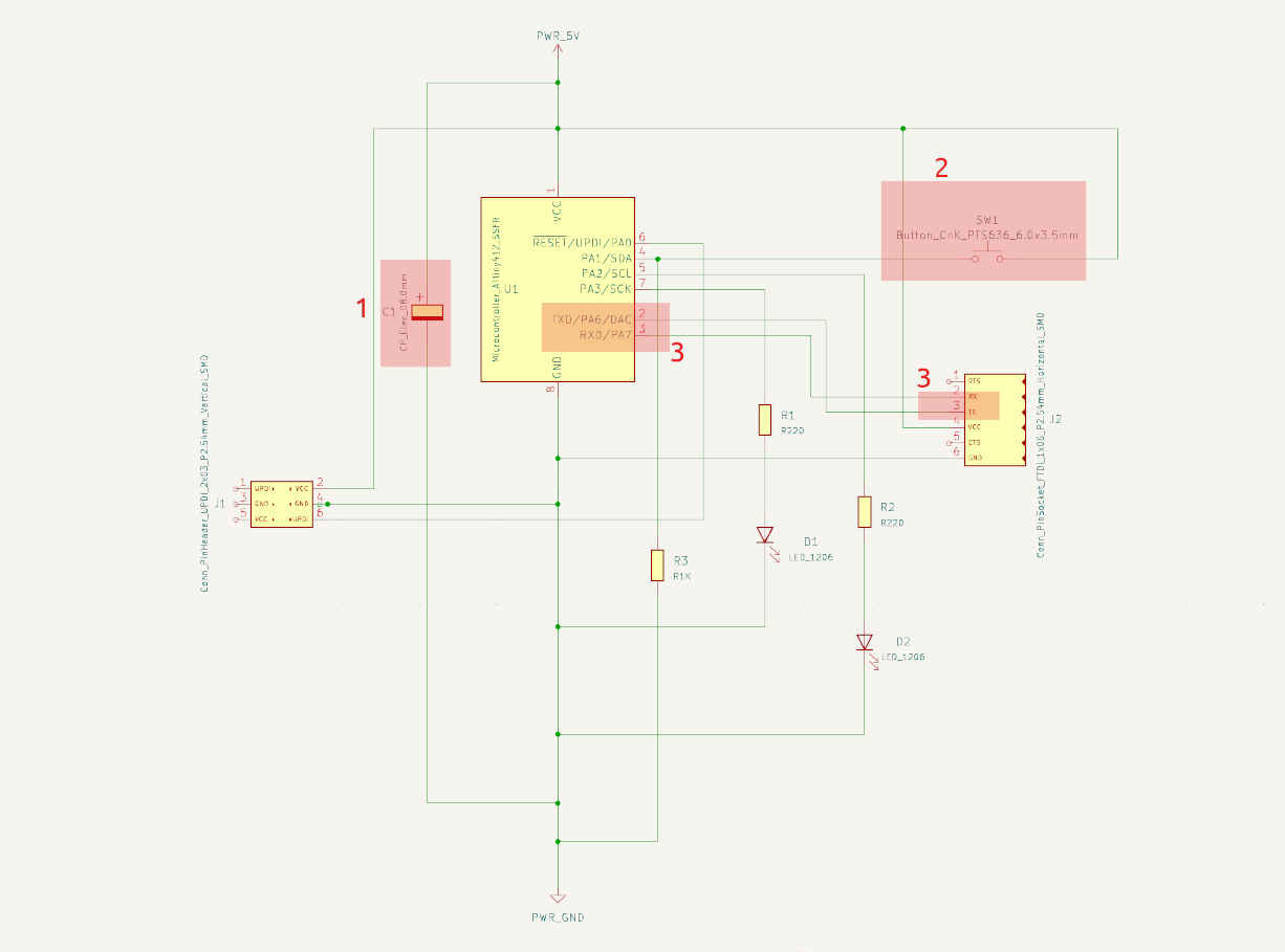
I connected the components with Wire (W) tool and got a result like this. When I first finished it, I assumed everything was fine, but I had no idea what awaited me in the following stages.
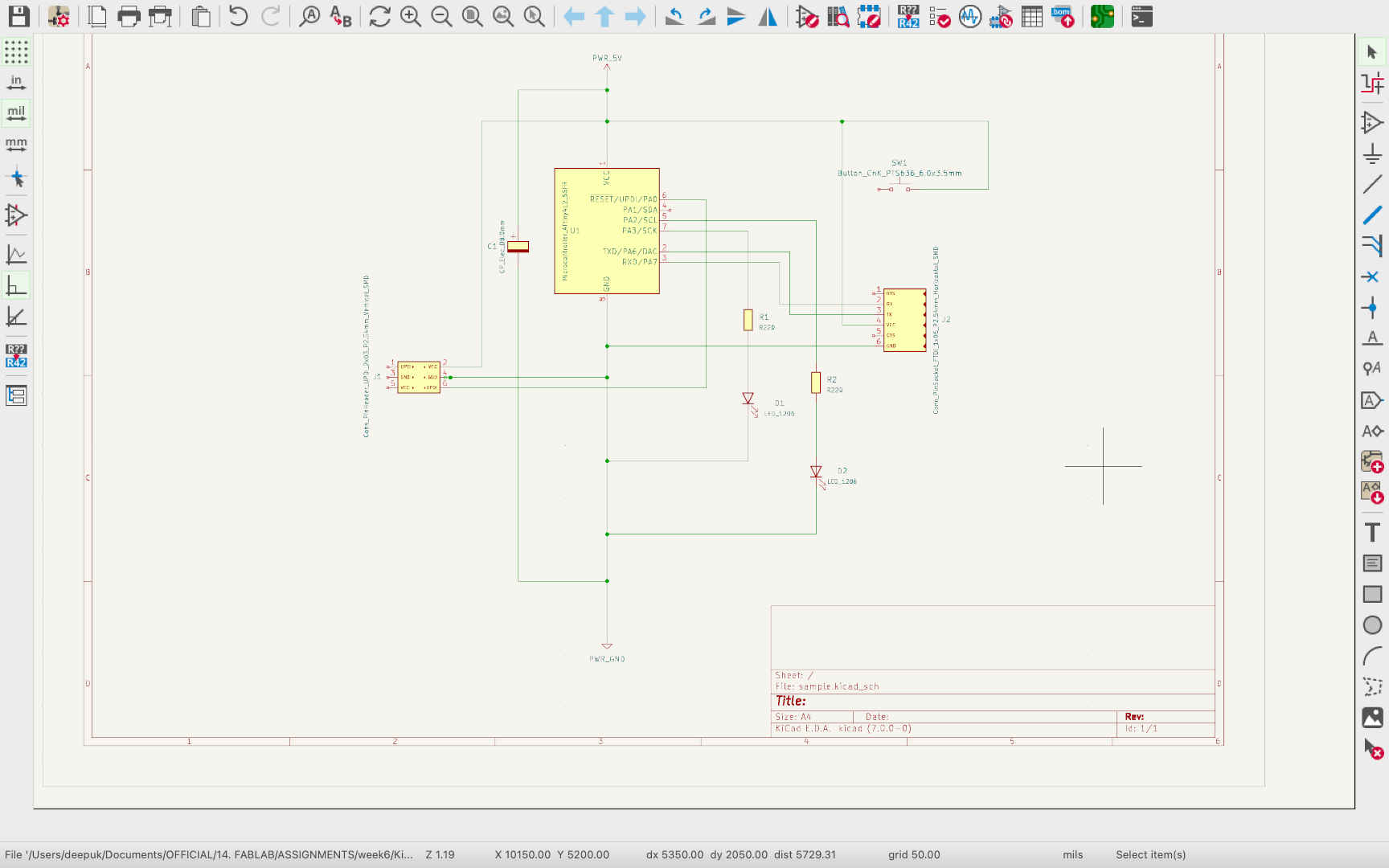
With the aid of my tutor and other students, I was able to identify three significant errors in my schematic. One was the improper choice of a large capacitor that was not required for this circuit. The second was the switch; I opted for a 2-legged switch, but our lab only had 4-legged switches. The third issue was the incorrect connection I made between the TXD and RXD ports.
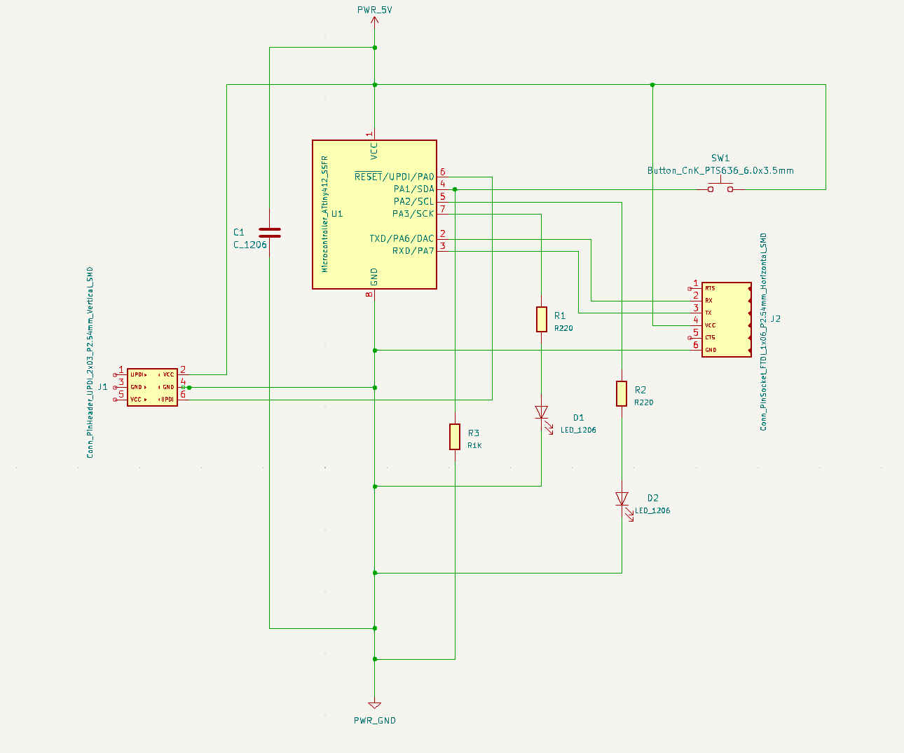
This was the revised design.
After making all the necessary changes, I run the Electrical Run Checkers ERC. I received 7 errors, which led me to realise how crucial it is to learn the rules for electrical design.
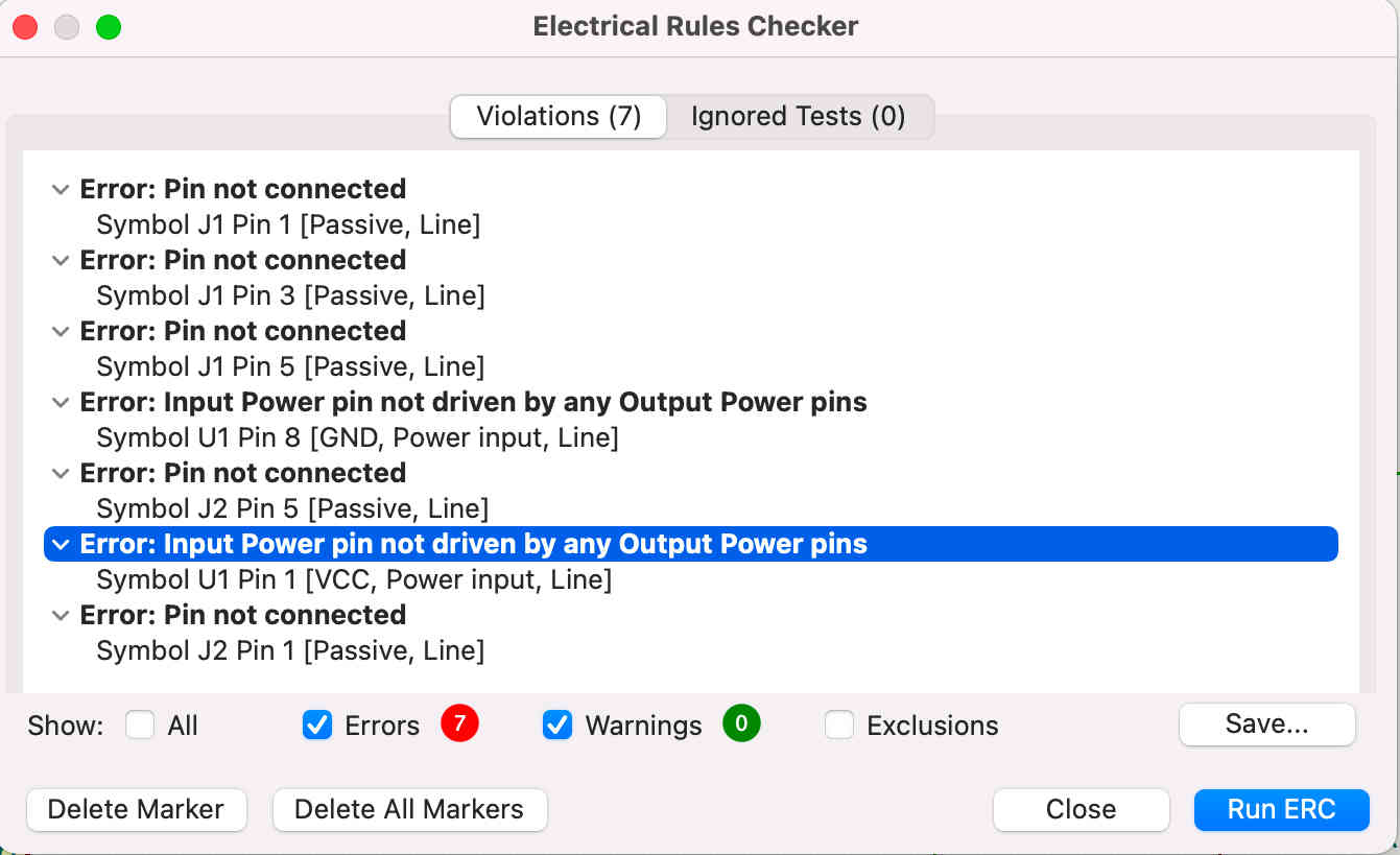
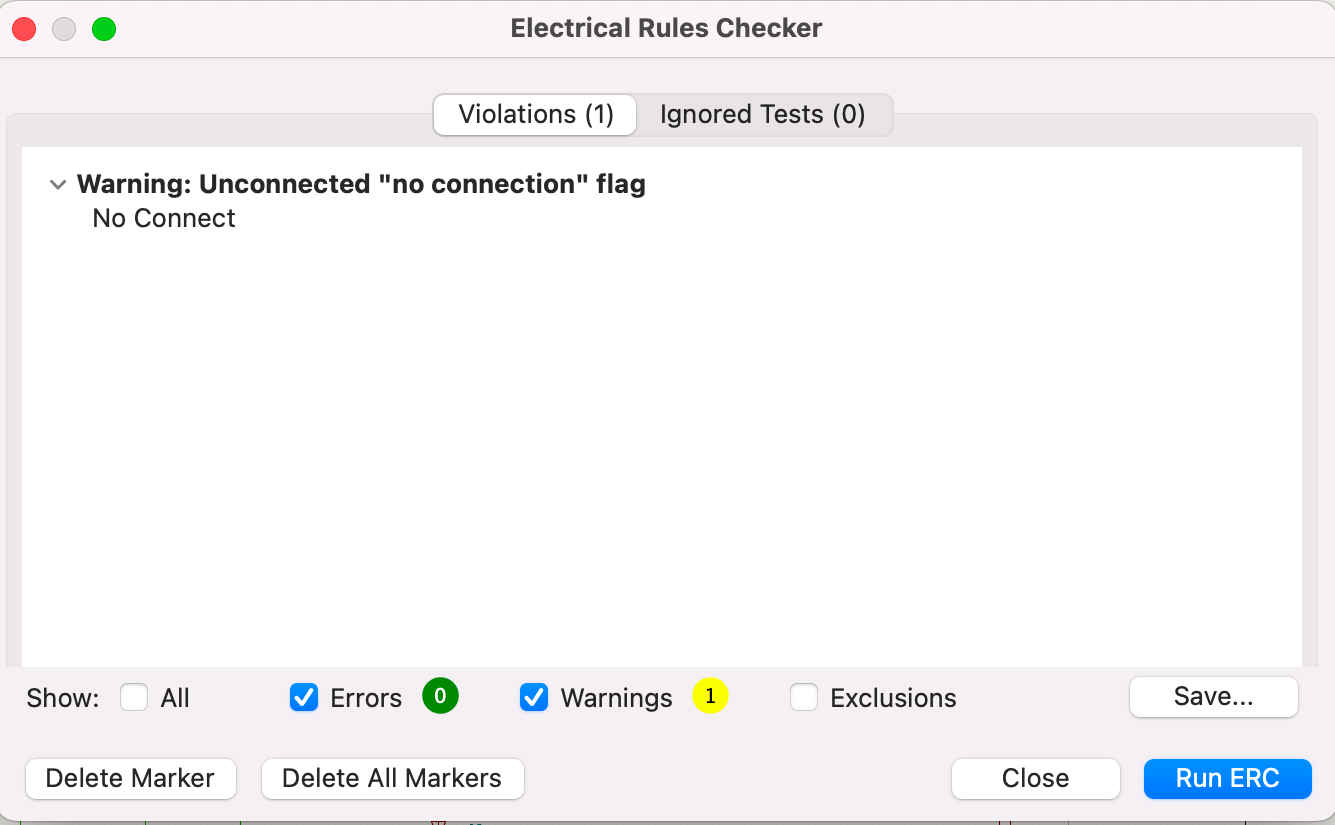
I found out the errors are beacuse of the 3 open pins in UPDI and 2 open pin in connection pin socket. I rectified those and Run ERC again and this time I got no errors.
Finally, it’s time to export this to a PCB file. And that’s what I came up with. I was a little disappointed because I had no idea that we needed to manually draw the connection lines from sctrach in the PCB file to make this look good.
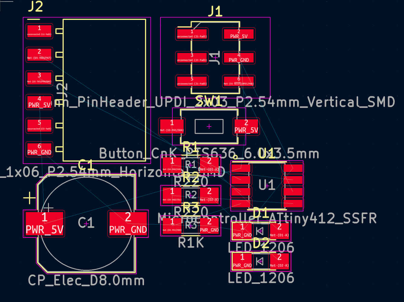
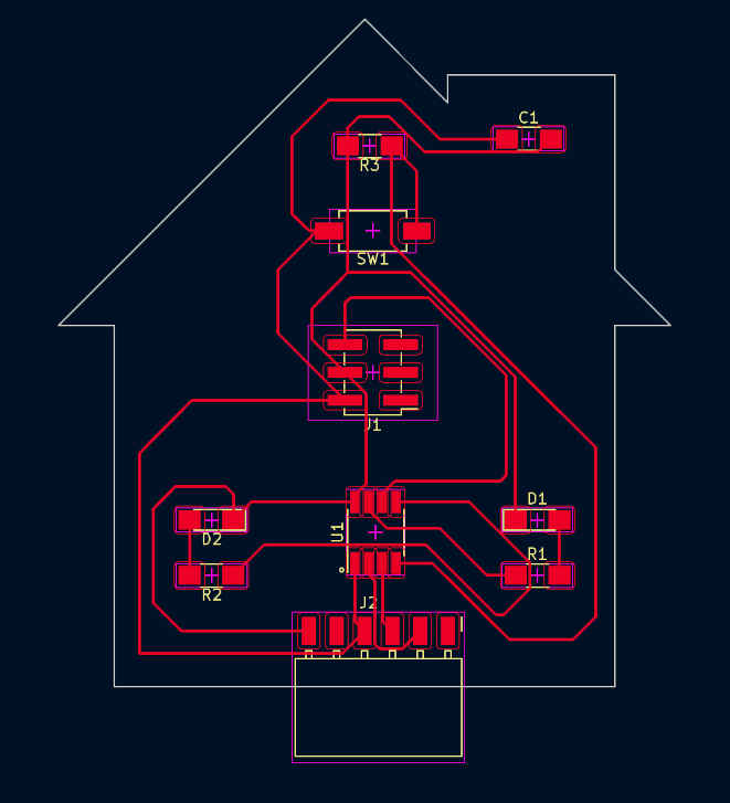
Then I realised that this is where it opens up the possibility of creativity for each designer, which excited me and prompted me to begin brainstorming for a creative design. And finally i ended up with something like this.
I thought this was the end, but then only i realised, like ERC in schematic, we need to check Design Rules here also. I then run the DRC (Design Rules Check) and received no errors. I was thrilled until I realised my biggest errors. I did not set the design constraints.
Now I went back to set the constraints.
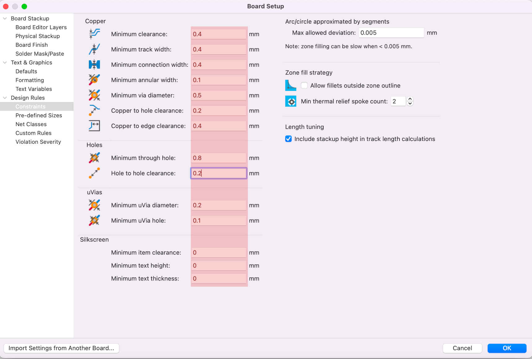
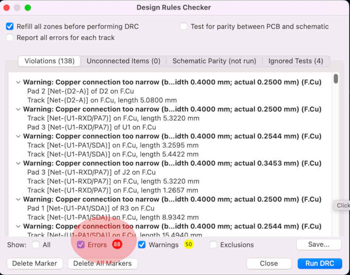
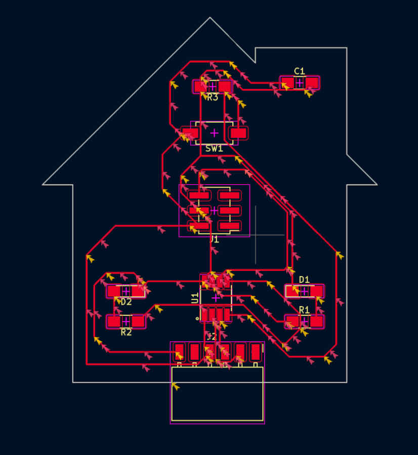
I Run the DRC check again and found out a bunch or errors and was little dissappointed, I then deleted all the connection and started redrawing from scratch.
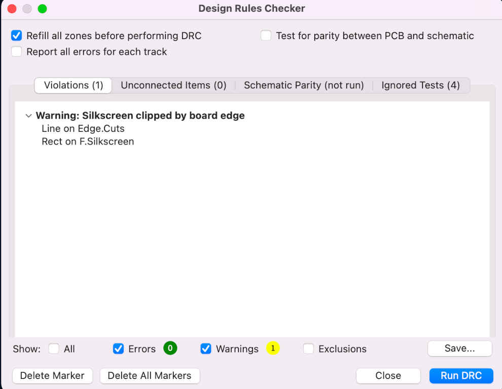
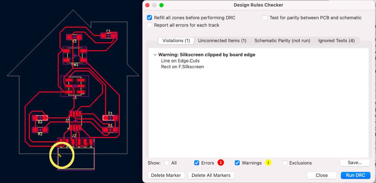
I redrew the connections, made some aesthetic changes, and ran the DRC once more; this time, I got only 1 error and that was because my pin was out of the boundary line and which was done deleberately. So I think this is fine.
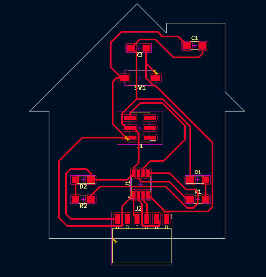
Final Circuit Design after all checks.
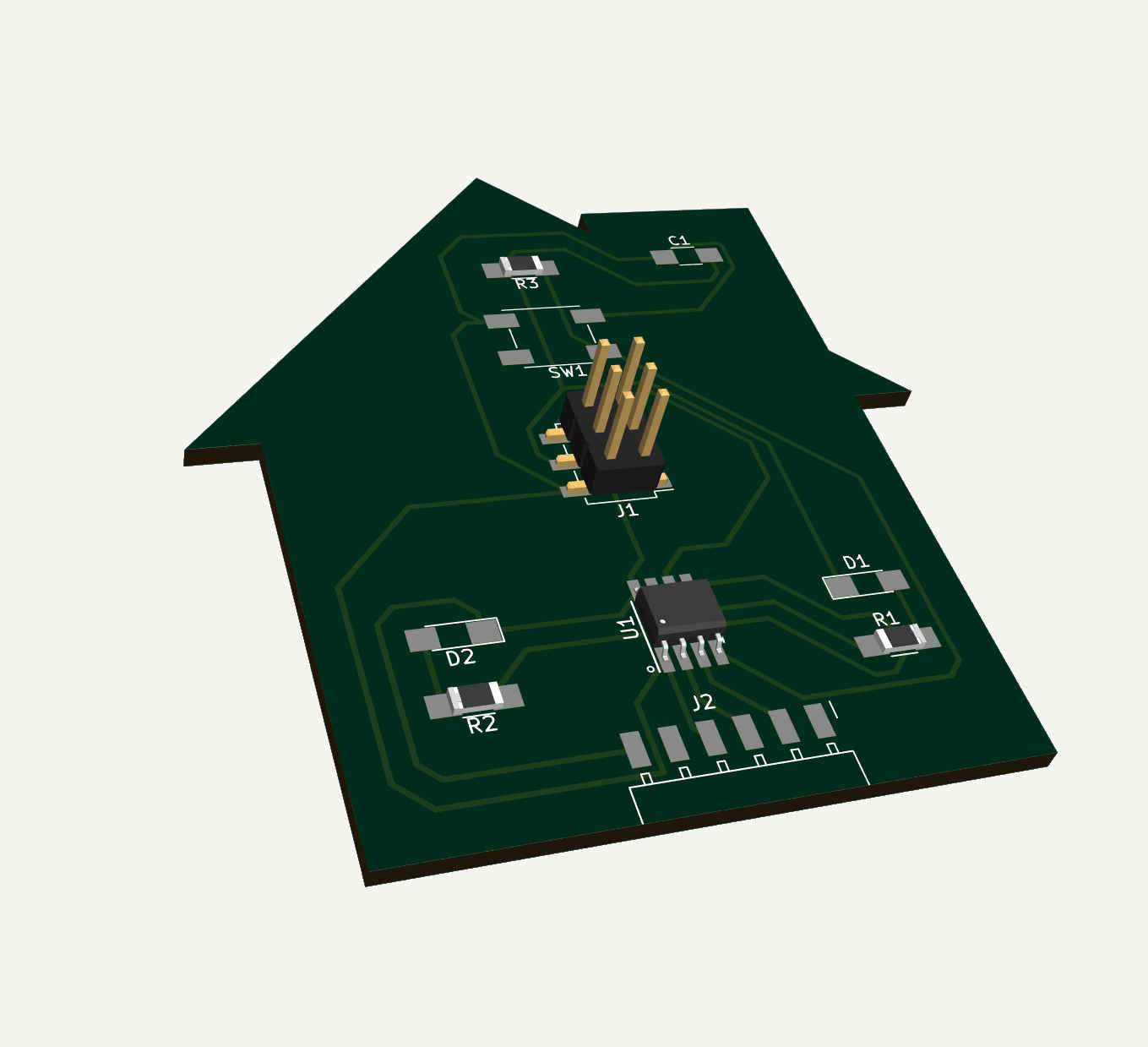
Final 3D output for the Circuit.
Some Add ons - What is ERC & DRC?
ERC (Electrical Rule Checking) and DRC (Design Rule Checking) are two important steps in the design verification process in Electronic Design Automation (EDA) tools.
ERC involves checking the electrical connectivity of the components in a design against a set of predefined rules. The main goal of ERC is to ensure that the design meets the required electrical specifications and can be manufactured without any issues. Some common ERC checks include pin connectivity, signal integrity, and power supply and ground checks.
On the other hand, DRC checks ensure that the design meets the manufacturing requirements such as minimum trace width and spacing, and other geometric constraints. DRC checks are performed after the layout of the design is completed, and the results are used to fix any issues before manufacturing the design.
Both ERC and DRC are crucial in ensuring the correctness and manufacturability of a design. By performing these checks, designers can identify any errors or violations of the defined rules and fix them before manufacturing. This helps save time and cost associated with redesigning or remanufacturing the design.
Group Assignment
Understanding the Test Equipment
1. Digital Multimeter
A digital multimeter (DMM) is a type of multimeter that uses a digital display to provide readings of the measured electrical quantities.
A digital multimeter typically has several measurement modes, including:
Voltage measurement: This mode is used to measure the voltage between two points in a circuit.

Current measurement: This mode is used to measure the current flowing through a circuit.

Resistance measurement: This mode is used to measure the resistance of a component or circuit.

Continuity testing: This mode is used to test for continuity between two points in a circuit,
                    indicating whether or not there is a complete path for current to flow.

Diode testing: This mode is used to test the functionality of a diode.
2. Oscilloscope
An oscilloscope is an electronic test instrument used to observe and analyze the waveform of electrical signals. An oscilloscope works by displaying the waveform of an electrical signal on a screen in the form of a graph. The horizontal axis of the graph represents time, while the vertical axis represents voltage. The user can adjust the time and voltage scales to obtain a more detailed view of the waveform.
Oscilloscopes can be used to measure various characteristics of a signal, such as its amplitude, frequency, and phase. They can also be used to measure the rise time, fall time, and pulse width of a signal.
3. Regulated Power Supply
A regulated power supply is an electronic circuit that converts unregulated AC or DC voltage into a constant, regulated DC voltage. A regulated power supply typically consists of a transformer, rectifier, smoothing capacitor, voltage regulator, and output filter. The transformer is used to convert the AC voltage into a lower or higher AC voltage depending on the application. The rectifier converts the AC voltage into a DC voltage, and the smoothing capacitor filters out any ripple or noise from the DC voltage. The voltage regulator then regulates the DC voltage to a constant level, and the output filter further removes any residual ripple or noise from the output.
4. Logic Analyzer
A logic analyzer is an electronic test instrument used to capture and analyze digital signals in a digital system. A logic analyzer captures digital signals by sampling multiple channels at high speed and then stores the captured data in a memory buffer. The captured data can then be displayed on a computer screen as a waveform, timing diagram, or a listing of digital values. The user can then analyze the captured data to detect timing problems, protocol errors, and other anomalies.
Detailed Study Report on our Group Assignment Page.
Downloads
Download PCB Milling PNG Files
Help Taken & References
Chat GPT used for doubt clearing and content helps.
Wikipedia used for content helps.